EP1397467B1 - Verfahren und vorrichtung zum stripping - Google Patents
Verfahren und vorrichtung zum stripping Download PDFInfo
- Publication number
- EP1397467B1 EP1397467B1 EP02737463A EP02737463A EP1397467B1 EP 1397467 B1 EP1397467 B1 EP 1397467B1 EP 02737463 A EP02737463 A EP 02737463A EP 02737463 A EP02737463 A EP 02737463A EP 1397467 B1 EP1397467 B1 EP 1397467B1
- Authority
- EP
- European Patent Office
- Prior art keywords
- stripping
- catalyst
- baffle
- section
- baffles
- Prior art date
- Legal status (The legal status is an assumption and is not a legal conclusion. Google has not performed a legal analysis and makes no representation as to the accuracy of the status listed.)
- Expired - Lifetime
Links
- 238000000034 method Methods 0.000 title claims abstract description 33
- 230000008569 process Effects 0.000 title claims abstract description 29
- 229930195733 hydrocarbon Natural products 0.000 claims description 51
- 150000002430 hydrocarbons Chemical class 0.000 claims description 51
- 239000002245 particle Substances 0.000 claims description 32
- 239000004215 Carbon black (E152) Substances 0.000 claims description 21
- 239000012530 fluid Substances 0.000 claims description 8
- 238000007599 discharging Methods 0.000 claims 1
- 239000003054 catalyst Substances 0.000 abstract description 184
- 230000004907 flux Effects 0.000 abstract description 14
- 238000006243 chemical reaction Methods 0.000 description 42
- 230000008929 regeneration Effects 0.000 description 30
- 238000011069 regeneration method Methods 0.000 description 30
- 239000007789 gas Substances 0.000 description 25
- 239000000571 coke Substances 0.000 description 23
- 238000000926 separation method Methods 0.000 description 16
- 239000000047 product Substances 0.000 description 10
- 238000005336 cracking Methods 0.000 description 9
- 239000000203 mixture Substances 0.000 description 9
- 239000003921 oil Substances 0.000 description 9
- 238000005243 fluidization Methods 0.000 description 7
- 238000012360 testing method Methods 0.000 description 7
- 230000008901 benefit Effects 0.000 description 6
- JTJMJGYZQZDUJJ-UHFFFAOYSA-N phencyclidine Chemical class C1CCCCN1C1(C=2C=CC=CC=2)CCCCC1 JTJMJGYZQZDUJJ-UHFFFAOYSA-N 0.000 description 6
- 230000032258 transport Effects 0.000 description 6
- 230000000694 effects Effects 0.000 description 5
- QVGXLLKOCUKJST-UHFFFAOYSA-N atomic oxygen Chemical compound [O] QVGXLLKOCUKJST-UHFFFAOYSA-N 0.000 description 4
- 238000002485 combustion reaction Methods 0.000 description 4
- 230000003628 erosive effect Effects 0.000 description 4
- 239000001257 hydrogen Substances 0.000 description 4
- 229910052739 hydrogen Inorganic materials 0.000 description 4
- 239000001301 oxygen Substances 0.000 description 4
- 229910052760 oxygen Inorganic materials 0.000 description 4
- 238000012545 processing Methods 0.000 description 4
- 230000002829 reductive effect Effects 0.000 description 4
- 230000001105 regulatory effect Effects 0.000 description 4
- 239000007787 solid Substances 0.000 description 4
- 238000009835 boiling Methods 0.000 description 3
- 230000003197 catalytic effect Effects 0.000 description 3
- 238000009826 distribution Methods 0.000 description 3
- 239000001307 helium Substances 0.000 description 3
- 229910052734 helium Inorganic materials 0.000 description 3
- SWQJXJOGLNCZEY-UHFFFAOYSA-N helium atom Chemical compound [He] SWQJXJOGLNCZEY-UHFFFAOYSA-N 0.000 description 3
- 239000000463 material Substances 0.000 description 3
- 230000036961 partial effect Effects 0.000 description 3
- 238000012546 transfer Methods 0.000 description 3
- IJGRMHOSHXDMSA-UHFFFAOYSA-N Atomic nitrogen Chemical compound N#N IJGRMHOSHXDMSA-UHFFFAOYSA-N 0.000 description 2
- OKTJSMMVPCPJKN-UHFFFAOYSA-N Carbon Chemical compound [C] OKTJSMMVPCPJKN-UHFFFAOYSA-N 0.000 description 2
- CURLTUGMZLYLDI-UHFFFAOYSA-N Carbon dioxide Chemical compound O=C=O CURLTUGMZLYLDI-UHFFFAOYSA-N 0.000 description 2
- UGFAIRIUMAVXCW-UHFFFAOYSA-N Carbon monoxide Chemical compound [O+]#[C-] UGFAIRIUMAVXCW-UHFFFAOYSA-N 0.000 description 2
- UFHFLCQGNIYNRP-UHFFFAOYSA-N Hydrogen Chemical compound [H][H] UFHFLCQGNIYNRP-UHFFFAOYSA-N 0.000 description 2
- IMNFDUFMRHMDMM-UHFFFAOYSA-N N-Heptane Chemical compound CCCCCCC IMNFDUFMRHMDMM-UHFFFAOYSA-N 0.000 description 2
- 229910000831 Steel Inorganic materials 0.000 description 2
- 229910052799 carbon Inorganic materials 0.000 description 2
- 230000008859 change Effects 0.000 description 2
- 239000012141 concentrate Substances 0.000 description 2
- 239000010779 crude oil Substances 0.000 description 2
- 238000013461 design Methods 0.000 description 2
- 238000005194 fractionation Methods 0.000 description 2
- 238000002347 injection Methods 0.000 description 2
- 239000007924 injection Substances 0.000 description 2
- 238000004519 manufacturing process Methods 0.000 description 2
- 238000002156 mixing Methods 0.000 description 2
- 239000011236 particulate material Substances 0.000 description 2
- 239000011148 porous material Substances 0.000 description 2
- 238000011084 recovery Methods 0.000 description 2
- 230000000630 rising effect Effects 0.000 description 2
- 239000010959 steel Substances 0.000 description 2
- XLYOFNOQVPJJNP-UHFFFAOYSA-N water Substances O XLYOFNOQVPJJNP-UHFFFAOYSA-N 0.000 description 2
- 229910001868 water Inorganic materials 0.000 description 2
- NINIDFKCEFEMDL-UHFFFAOYSA-N Sulfur Chemical compound [S] NINIDFKCEFEMDL-UHFFFAOYSA-N 0.000 description 1
- 229910021536 Zeolite Inorganic materials 0.000 description 1
- 238000005299 abrasion Methods 0.000 description 1
- 238000009825 accumulation Methods 0.000 description 1
- 239000000956 alloy Substances 0.000 description 1
- 229910045601 alloy Inorganic materials 0.000 description 1
- 238000003491 array Methods 0.000 description 1
- 230000009286 beneficial effect Effects 0.000 description 1
- 230000015572 biosynthetic process Effects 0.000 description 1
- 239000006227 byproduct Substances 0.000 description 1
- 229910002092 carbon dioxide Inorganic materials 0.000 description 1
- 239000001569 carbon dioxide Substances 0.000 description 1
- 229910002091 carbon monoxide Inorganic materials 0.000 description 1
- 238000004939 coking Methods 0.000 description 1
- 230000001276 controlling effect Effects 0.000 description 1
- 230000008021 deposition Effects 0.000 description 1
- HNPSIPDUKPIQMN-UHFFFAOYSA-N dioxosilane;oxo(oxoalumanyloxy)alumane Chemical compound O=[Si]=O.O=[Al]O[Al]=O HNPSIPDUKPIQMN-UHFFFAOYSA-N 0.000 description 1
- 239000003546 flue gas Substances 0.000 description 1
- 150000002431 hydrogen Chemical class 0.000 description 1
- 230000006872 improvement Effects 0.000 description 1
- 238000005259 measurement Methods 0.000 description 1
- VUZPPFZMUPKLLV-UHFFFAOYSA-N methane;hydrate Chemical compound C.O VUZPPFZMUPKLLV-UHFFFAOYSA-N 0.000 description 1
- 230000004048 modification Effects 0.000 description 1
- 238000012986 modification Methods 0.000 description 1
- 229910052757 nitrogen Inorganic materials 0.000 description 1
- 230000003647 oxidation Effects 0.000 description 1
- 238000007254 oxidation reaction Methods 0.000 description 1
- 230000002093 peripheral effect Effects 0.000 description 1
- 239000003208 petroleum Substances 0.000 description 1
- 239000000700 radioactive tracer Substances 0.000 description 1
- 239000011819 refractory material Substances 0.000 description 1
- 230000000284 resting effect Effects 0.000 description 1
- 230000000717 retained effect Effects 0.000 description 1
- 239000000126 substance Substances 0.000 description 1
- 229910052717 sulfur Inorganic materials 0.000 description 1
- 239000011593 sulfur Substances 0.000 description 1
- 238000010998 test method Methods 0.000 description 1
- 230000000007 visual effect Effects 0.000 description 1
- 239000010457 zeolite Substances 0.000 description 1
Images



Classifications
-
- B—PERFORMING OPERATIONS; TRANSPORTING
- B01—PHYSICAL OR CHEMICAL PROCESSES OR APPARATUS IN GENERAL
- B01J—CHEMICAL OR PHYSICAL PROCESSES, e.g. CATALYSIS OR COLLOID CHEMISTRY; THEIR RELEVANT APPARATUS
- B01J8/00—Chemical or physical processes in general, conducted in the presence of fluids and solid particles; Apparatus for such processes
- B01J8/005—Separating solid material from the gas/liquid stream
- B01J8/0055—Separating solid material from the gas/liquid stream using cyclones
-
- B—PERFORMING OPERATIONS; TRANSPORTING
- B01—PHYSICAL OR CHEMICAL PROCESSES OR APPARATUS IN GENERAL
- B01D—SEPARATION
- B01D53/00—Separation of gases or vapours; Recovering vapours of volatile solvents from gases; Chemical or biological purification of waste gases, e.g. engine exhaust gases, smoke, fumes, flue gases, aerosols
- B01D53/02—Separation of gases or vapours; Recovering vapours of volatile solvents from gases; Chemical or biological purification of waste gases, e.g. engine exhaust gases, smoke, fumes, flue gases, aerosols by adsorption, e.g. preparative gas chromatography
- B01D53/06—Separation of gases or vapours; Recovering vapours of volatile solvents from gases; Chemical or biological purification of waste gases, e.g. engine exhaust gases, smoke, fumes, flue gases, aerosols by adsorption, e.g. preparative gas chromatography with moving adsorbents, e.g. rotating beds
- B01D53/10—Separation of gases or vapours; Recovering vapours of volatile solvents from gases; Chemical or biological purification of waste gases, e.g. engine exhaust gases, smoke, fumes, flue gases, aerosols by adsorption, e.g. preparative gas chromatography with moving adsorbents, e.g. rotating beds with dispersed adsorbents
-
- B—PERFORMING OPERATIONS; TRANSPORTING
- B01—PHYSICAL OR CHEMICAL PROCESSES OR APPARATUS IN GENERAL
- B01J—CHEMICAL OR PHYSICAL PROCESSES, e.g. CATALYSIS OR COLLOID CHEMISTRY; THEIR RELEVANT APPARATUS
- B01J38/00—Regeneration or reactivation of catalysts, in general
- B01J38/04—Gas or vapour treating; Treating by using liquids vaporisable upon contacting spent catalyst
-
- B—PERFORMING OPERATIONS; TRANSPORTING
- B01—PHYSICAL OR CHEMICAL PROCESSES OR APPARATUS IN GENERAL
- B01J—CHEMICAL OR PHYSICAL PROCESSES, e.g. CATALYSIS OR COLLOID CHEMISTRY; THEIR RELEVANT APPARATUS
- B01J8/00—Chemical or physical processes in general, conducted in the presence of fluids and solid particles; Apparatus for such processes
- B01J8/008—Details of the reactor or of the particulate material; Processes to increase or to retard the rate of reaction
-
- B—PERFORMING OPERATIONS; TRANSPORTING
- B01—PHYSICAL OR CHEMICAL PROCESSES OR APPARATUS IN GENERAL
- B01J—CHEMICAL OR PHYSICAL PROCESSES, e.g. CATALYSIS OR COLLOID CHEMISTRY; THEIR RELEVANT APPARATUS
- B01J8/00—Chemical or physical processes in general, conducted in the presence of fluids and solid particles; Apparatus for such processes
- B01J8/18—Chemical or physical processes in general, conducted in the presence of fluids and solid particles; Apparatus for such processes with fluidised particles
- B01J8/24—Chemical or physical processes in general, conducted in the presence of fluids and solid particles; Apparatus for such processes with fluidised particles according to "fluidised-bed" technique
- B01J8/26—Chemical or physical processes in general, conducted in the presence of fluids and solid particles; Apparatus for such processes with fluidised particles according to "fluidised-bed" technique with two or more fluidised beds, e.g. reactor and regeneration installations
- B01J8/28—Chemical or physical processes in general, conducted in the presence of fluids and solid particles; Apparatus for such processes with fluidised particles according to "fluidised-bed" technique with two or more fluidised beds, e.g. reactor and regeneration installations the one above the other
-
- B—PERFORMING OPERATIONS; TRANSPORTING
- B01—PHYSICAL OR CHEMICAL PROCESSES OR APPARATUS IN GENERAL
- B01J—CHEMICAL OR PHYSICAL PROCESSES, e.g. CATALYSIS OR COLLOID CHEMISTRY; THEIR RELEVANT APPARATUS
- B01J8/00—Chemical or physical processes in general, conducted in the presence of fluids and solid particles; Apparatus for such processes
- B01J8/18—Chemical or physical processes in general, conducted in the presence of fluids and solid particles; Apparatus for such processes with fluidised particles
- B01J8/24—Chemical or physical processes in general, conducted in the presence of fluids and solid particles; Apparatus for such processes with fluidised particles according to "fluidised-bed" technique
- B01J8/34—Chemical or physical processes in general, conducted in the presence of fluids and solid particles; Apparatus for such processes with fluidised particles according to "fluidised-bed" technique with stationary packing material in the fluidised bed, e.g. bricks, wire rings, baffles
-
- C—CHEMISTRY; METALLURGY
- C10—PETROLEUM, GAS OR COKE INDUSTRIES; TECHNICAL GASES CONTAINING CARBON MONOXIDE; FUELS; LUBRICANTS; PEAT
- C10G—CRACKING HYDROCARBON OILS; PRODUCTION OF LIQUID HYDROCARBON MIXTURES, e.g. BY DESTRUCTIVE HYDROGENATION, OLIGOMERISATION, POLYMERISATION; RECOVERY OF HYDROCARBON OILS FROM OIL-SHALE, OIL-SAND, OR GASES; REFINING MIXTURES MAINLY CONSISTING OF HYDROCARBONS; REFORMING OF NAPHTHA; MINERAL WAXES
- C10G11/00—Catalytic cracking, in the absence of hydrogen, of hydrocarbon oils
- C10G11/14—Catalytic cracking, in the absence of hydrogen, of hydrocarbon oils with preheated moving solid catalysts
- C10G11/18—Catalytic cracking, in the absence of hydrogen, of hydrocarbon oils with preheated moving solid catalysts according to the "fluidised-bed" technique
-
- C—CHEMISTRY; METALLURGY
- C10—PETROLEUM, GAS OR COKE INDUSTRIES; TECHNICAL GASES CONTAINING CARBON MONOXIDE; FUELS; LUBRICANTS; PEAT
- C10G—CRACKING HYDROCARBON OILS; PRODUCTION OF LIQUID HYDROCARBON MIXTURES, e.g. BY DESTRUCTIVE HYDROGENATION, OLIGOMERISATION, POLYMERISATION; RECOVERY OF HYDROCARBON OILS FROM OIL-SHALE, OIL-SAND, OR GASES; REFINING MIXTURES MAINLY CONSISTING OF HYDROCARBONS; REFORMING OF NAPHTHA; MINERAL WAXES
- C10G11/00—Catalytic cracking, in the absence of hydrogen, of hydrocarbon oils
- C10G11/14—Catalytic cracking, in the absence of hydrogen, of hydrocarbon oils with preheated moving solid catalysts
- C10G11/18—Catalytic cracking, in the absence of hydrogen, of hydrocarbon oils with preheated moving solid catalysts according to the "fluidised-bed" technique
- C10G11/182—Regeneration
-
- B—PERFORMING OPERATIONS; TRANSPORTING
- B01—PHYSICAL OR CHEMICAL PROCESSES OR APPARATUS IN GENERAL
- B01J—CHEMICAL OR PHYSICAL PROCESSES, e.g. CATALYSIS OR COLLOID CHEMISTRY; THEIR RELEVANT APPARATUS
- B01J2208/00—Processes carried out in the presence of solid particles; Reactors therefor
- B01J2208/00796—Details of the reactor or of the particulate material
- B01J2208/00823—Mixing elements
- B01J2208/00831—Stationary elements
- B01J2208/0084—Stationary elements inside the bed, e.g. baffles
-
- C—CHEMISTRY; METALLURGY
- C10—PETROLEUM, GAS OR COKE INDUSTRIES; TECHNICAL GASES CONTAINING CARBON MONOXIDE; FUELS; LUBRICANTS; PEAT
- C10G—CRACKING HYDROCARBON OILS; PRODUCTION OF LIQUID HYDROCARBON MIXTURES, e.g. BY DESTRUCTIVE HYDROGENATION, OLIGOMERISATION, POLYMERISATION; RECOVERY OF HYDROCARBON OILS FROM OIL-SHALE, OIL-SAND, OR GASES; REFINING MIXTURES MAINLY CONSISTING OF HYDROCARBONS; REFORMING OF NAPHTHA; MINERAL WAXES
- C10G2300/00—Aspects relating to hydrocarbon processing covered by groups C10G1/00 - C10G99/00
- C10G2300/40—Characteristics of the process deviating from typical ways of processing
- C10G2300/4093—Catalyst stripping
Definitions
- This invention relates to processes and apparatuses for the fluidized contacting of catalyst with hydrocarbons. More specifically, this invention relates to processes and apparatuses for stripping entrained or adsorbed hydrocarbons from catalyst particles.
- a variety of processes contact finely divided particulate material with a hydrocarbon containing feed under conditions wherein a fluid maintains the particles in a fluidized condition to effect transport of the solid particles to different stages of the process.
- Catalyst cracking is a prime example of such a process that contacts hydrocarbons in a reaction zone with a catalyst composed of finely divided particulate material.
- the hydrocarbon feed fluidizes the catalyst and typically transports it in a riser as the catalyst promotes the cracking reaction.
- substantial amounts of hydrocarbon called coke
- a high temperature regeneration within a regeneration zone bums coke from the catalyst by contact with an oxygen-containing stream that again serves as a fluidization medium.
- Coke-containing catalyst referred to herein as spent catalyst
- spent catalyst is continually removed from the reaction zone and replaced by essentially coke-free catalyst from the regeneration zone.
- Fluidization of the catalyst particles by various gaseous streams allows the transport of catalyst between the reaction zone and regeneration zone.
- Methods for cracking hydrocarbons in a fluidized stream of catalyst, transporting catalyst between reaction and regeneration zones and combusting coke in the regenerator are well known to those skilled in the art of FCC processes. To this end, the art is replete with vessel configurations for contacting catalyst particles with feed and regeneration gas, respectively.
- a majority of the hydrocarbon vapors that contact the catalyst in the reaction zone are separated from the solid particles by ballistic and/or centrifugal separation methods within the reaction zone.
- the catalyst particles employed in an FCC process have a large surface area, which is due to a great multitude of pores located in the particles.
- the catalytic materials retain hydrocarbons within their pores, upon the external surface of the catalyst and in the spaces between individual catalyst particles as they enter the stripping zone.
- the quantity of hydrocarbons retained on each individual catalyst particle is very small, the large amount of catalyst and the high catalyst circulation rate which is typically used in a modem FCC process results in a significant quantity of hydrocarbons being withdrawn from the reaction zone with the catalyst.
- the most common method of stripping the catalyst passes a stripping gas, usually steam, through a flowing stream of catalyst, counter-current to its direction of flow.
- a stripping gas usually steam
- Such steam stripping operations with varying degrees of efficiency, remove the hydrocarbon vapors which are entrained with the catalyst and adsorbed on the catalyst.
- Contact of the catalyst with a stripping medium may be accomplished in a simple open vessel as demonstrated by US-A-4,481,103.
- the efficiency of catalyst stripping is increased by using vertically spaced baffles to cascade the catalyst from side to side as it moves down a stripping apparatus and counter-currently contacts a stripping medium. Moving the catalyst horizontally increases contact between the catalyst and the stripping medium so that more hydrocarbons are removed from the catalyst. In these arrangements, the catalyst is given a labyrinthine path through a series of baffles located at different levels. Catalyst and gas contact is increased by this arrangement that leaves no open vertical path of significant cross-section through the stripping apparatus.
- Variations in the baffles include the addition of skirts about the trailing edge of the baffle as depicted in US-A-2,994,659 and the use of multiple linear baffle sections at different baffle levels as demonstrated in FIG. 3 of US-A-4,500,423.
- a variation in introducing the stripping medium is shown in US-A-2,541,801 where a quantity of fluidizing gas is admitted at a number of discrete locations.
- the baffles are typically oriented to have an angle of 45° with respect to the horizontal.
- the sloped baffles assure that catalyst moves off the tray down to the next level in the stripping vessel.
- the sloped trays each occupy substantial elevation, they limit the number of trays that can be installed in a given height of a stripping vessel. The greater the number of trays in the stripping vessel, the greater the overall performance.
- sloped baffles generate a differential pressure head between holes that are lower in elevation on a baffle compared to the holes which are higher in elevation on the baffle. Because the pressure is greater at lower elevations on the baffle, the velocity through the jets on the baffle is greater at higher elevations on the baffle.
- WO 91/00899 discloses a stripping vessel with perforated horizontal trays.
- the fluidization in the stripping vessel is such that the catalyst descends from one tray to another substantially only through downcomer sections of respective trays.
- the catalyst material forms a dense bed upon the top surface of each tray without substantial quantities of catalyst weeping through the perforations in the tray.
- This reference also teaches the use of deflector plates above downcomers that are vertically aligned at the center of an annular tray and trays comprising wire mesh or arrays of bars.
- Delta coke is the weight percent coke on spent catalyst less the weight percent coke on regenerated catalyst. Reducing delta coke in the FCC process permits a lowering of the regenerator temperature. More of the resulting, relatively cooler regenerated catalyst is required to supply the fixed heat load in the reaction zone. Hence, the reaction zone may operate at a higher catalyst-to-feed or catalyst-to-oil (C/O) ratio. The higher C/O ratio increases conversion which increases the production of valuable products. Consequently, improved stripping results in improved conversion.
- C/O catalyst-to-oil
- a stripping operation that reduces the production of delta coke by 0.05 wt-% can lower the regenerator temperature by -9° to -7°C (15° to 20°F) and permit a C/O ratio increase in the range of 6%.
- US-A-5,531,884 shows a modification to a baffle-style stripping vessel that incorporates one or more rings of large vertical conduits to provide an additional catalyst and gas circulation path across the baffles. It is also known to concentrate openings in a very centralized portion of the stripping baffles.
- baffles with perforated sections that permit substantial amounts of catalyst to pass therethrough will provide improved stripping efficiency and catalyst flux through the stripping vessel. It was also unexpectedly found that the stripping efficiency increases with higher catalyst flux when using horizontal baffles with perforated sections comprising grates of this invention.
- the utilization of baffles with imperforate sections that are vertically out of alignment on adjacent baffles generates sufficient transverse movement of the catalyst across each baffle to allow the stripping medium to rise through the catalyst and provide better mixing.
- Providing the baffles with downcomer sections that are vertically aligned with imperforate sections of adjacent baffles further encourages transverse catalyst movement.
- the process of this invention has benefits at all flux rates, has particular benefits at flux rates of at least 292,920 kg/hr/m 2 (60,000 1bs/hr/ft 2 ) of stripping vessel area and is particularly useful at flux rates of at least 537,020 kg/hr/m 2 (110,000 1bs/hr/ft 2 ) of stripping vessel area.
- the improved stripping design achieves high stripping efficiencies at very low steam rates, which reduces overall FCC unit operating costs.
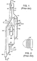
- FIG. 1 is representative of the prior art and shows a schematic elevation view of a stacked FCC regenerator-reactor and stripping arrangement.
- FIG. 2 is a horizontal section taken across the stripping vessel of FIG. 1.
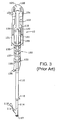
- FIG. 3 is a schematic elevational view of an alternate arrangement for an FCC reactor.
- FIG. 4 is a partial schematic elevational view of a modified stripping vessel for replacement of a stripping vessel shown in FIG. 1.
- FIG. 5 is a cross-sectional view of the baffle for the stripping vessel of FIG. 4 taken at segment 5-5 in FIG. 4.
- FIG. 6 is a cross-sectional view of an alternative baffle for the stripping vessel of FIG. 4 taken at segment 5-5 in FIG. 4.
- FIG. 7 is a partial schematic elevational view of a modified stripping vessel for replacement of a stripping vessel shown in FIG. 3.
- FIG. 8 is a cross-sectional view of a unitary baffle from the stripping vessel in FIG. 7 taken at segment 8-8 in FIG. 7.
- FIG. 9 is a cross-sectional view of a bifurcated baffle from the stripping vessel in FIG. 7 taken at segment 9-9 in FIG. 7.
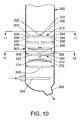
- FIG. 10 is a partial schematic elevational view of a stripping zone of a further alternative arrangement for an FCC reactor.
- FIG. 11 is a plan view of a unitary baffle of FIG. 10 taken from segment 11-11 in FIG. 10.
- FIG. 12 is a plan view of the bifurcated baffle of FIG. 10 taken from segment 12-12 in FIG. 10.
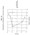
- FIG. 13 is a graph comparing stripping efficiencies of a stripping vessel with conventional baffles to a stripping vessel with baffles of the present invention.
- the typical feed to an FCC unit is a gas oil such as a light or vacuum gas oil.
- Other petroleum-derived feed streams to an FCC unit may comprise a diesel boiling range mixture of hydrocarbons or heavier hydrocarbons such as reduced crude oils. It is preferred that the feed stream consist of a mixture of hydrocarbons having boiling points, as determined by the appropriate ASTM test method, above 230°C (446°F) and more preferably above 290°C (554°F). It is becoming customary to refer to FCC-type units which are processing heavier feedstocks, such as atmospheric reduced crudes, as residual crude cracking units, or resid cracking units. The process and apparatus of this invention can be used for either FCC or residual cracking operations. For convenience, the remainder of this specification will only make reference to the FCC process.
- An FCC process unit comprises a reaction zone and a catalyst regeneration zone.
- a feed stream is contacted with finely divided fluidized solid particles or catalyst maintained at an elevated temperature and at a moderate positive pressure.
- contacting of feed and catalyst usually takes place in a riser conduit, but may occur in any effective arrangement such as the known devices for short contact time contacting.
- a riser it comprises a principally vertical conduit as the main reaction site, with the effluent of the conduit emptying into a large volume process vessel, which is called the reactor vessel or may be referred to as a separation vessel.
- the residence time of catalyst and hydrocarbons in the riser needed for substantial completion of the cracking reactions is only a few seconds or less.
- the flowing vapor/catalyst stream leaving the riser may pass from the riser to a solids-vapor separation device located within the separation vessel or may enter the separation vessel directly without passing through an intermediate separation apparatus.
- a solids-vapor separation device located within the separation vessel or may enter the separation vessel directly without passing through an intermediate separation apparatus.
- Much of the catalyst drops out of the flowing vapor/catalyst stream as the stream leaves the riser and enters the separation vessel.
- One or more additional solids/vapor separation devices is normally located within and at the top of the large separation vessel.
- the products of the reaction are separated from a portion of catalyst which is still carried by the vapor stream by means of the cyclone or cyclones and the vapor is vented from the cyclone and separation zone.
- the spent catalyst falls downward to a lower location within the separation vessel.
- a stripping zone is usually located near a lower part of the reactor vessel to remove hydrocarbons from the catalyst and comprises a stripping vessel separate from the riser and reactor vessel. Cataly
- the rate of conversion of the feedstock within the reaction zone is controlled by regulation of the temperature, activity of the catalyst and quantity of the catalyst (i.e., catalyst-to-oil ratio) maintained within the reaction zone.
- the most common method of regulating the temperature in the reaction zone is by regulating the rate of circulation of catalyst from the regeneration zone to the reaction zone, which simultaneously changes the catalyst-to-oil ratio. That is, if it is desired to increase the conversion rate within the reaction zone, the rate of flow of catalyst from the regeneration zone to the reaction zone is increased. This results in more catalyst being present in the reaction zone for the same volume of oil charged thereto. Since the temperature within the regeneration zone under normal operations is considerably higher than the temperature within the reaction zone, an increase in the rate of circulation of catalyst from the regeneration zone to the reaction zone results in an increase in the reaction zone temperature.
- the chemical composition and structure of the feed to an FCC unit will affect the amount of coke deposited upon the catalyst in the reaction zone. Normally, the higher the molecular weight, Conradson carbon, heptane insolubles and carbon-to-hydrogen ratio of the feedstock, the higher will be the coke level on the spent catalyst. Greater conversion also increases the coke level on spent catalyst. Also, high levels of combined nitrogen, such as found in shale-derived oils, will increase the coke level on spent catalyst. Processing of heavier feedstocks, such as deasphalted oils or atmospheric bottoms from a crude oil fractionation unit (commonly referred to as reduced crude) results in an increase in some or all of these factors and therefore causes an increase in the coke level on spent catalyst.
- the term "spent catalyst” is intended to indicate catalyst employed in the reaction zone which is being transferred to the regeneration zone for the removal of coke deposits. The term is not intended to be indicative of a total lack of catalytic activity by the catalyst particles.
- used catalyst is intended to have the same meaning as the term "spent catalyst”.
- the reaction zone which is normally referred to as a "riser” due to the widespread use of a vertical tubular conduit, is maintained at high temperature conditions which generally include a temperature above 425°C (797°F).
- the reaction zone is maintained at cracking conditions which include a temperature of from 480° to 590°C (896° to 1094°F) and a pressure of from 65 to 500 kPa (9.4 to 72.5 psia) but preferably less than 275 kPa (39.9 psia).
- the catalyst-to-oil ratio based on the weight of catalyst and feed hydrocarbons entering the bottom of the riser, may range up to 20:1 but is preferably between 4:1 and 10:1.
- Hydrogen is not normally added to the riser, although hydrogen addition is known in the art. On occasion, steam may be passed into the riser.
- the average residence time of catalyst in the riser is preferably less than 5 seconds.
- the type of catalyst employed in the process may be chosen from a variety of commercially available catalysts. A catalyst comprising a zeolite base material is preferred, but the older style amorphous catalyst can be used if desired. Further information on the operation of FCC reaction zones may be obtained from US-A-4,541,922, US-A-4,541,923 and the patents cited above.
- catalyst In an FCC process, catalyst is continuously circulated from the reaction zone to the regeneration zone and then again to the reaction zone.
- the catalyst therefore acts as a vehicle for the transfer of heat from zone to zone as well as providing the necessary catalytic activity.
- Any FCC catalyst can be used for the process.
- the particles will typically have a size of less than 100 microns.
- Catalyst which is being withdrawn from the regeneration zone is referred to as "regenerated" catalyst.
- the catalyst charged to the regeneration zone is brought into contact with an oxygen-containing gas such as air or oxygen-enriched air under conditions which result in combustion of the coke. This results in an increase in the temperature of the catalyst and the generation of a large amount of hot gas which is removed from the regeneration zone as a gas stream referred to as a flue gas stream.
- the regeneration zone is normally operated at a temperature of from 600°C (1112°F) to 800°C (1472°F). Additional information on the operation of FCC reaction and regeneration zones may be obtained from US-A-4,431,749, US-A-4,419,221 and US-A-4,220,623.
- the catalyst regeneration zone is preferably operated at a pressure of from 35 to 500 kPa (5.1 to 72.5 psia).
- the spent catalyst being charged to the regeneration zone may contain from 0.2 to 15 wt-% coke.
- This coke is predominantly comprised of carbon and can contain from 3 to 15 wt-% hydrogen, as well as sulfur and other elements.
- the oxidation of coke will produce the common combustion products: carbon dioxide, carbon monoxide and water.
- the regeneration zone may take several configurations, with regeneration being performed in one or more stages. Further variety is possible due to the fact that regeneration may be accomplished with the fluidized catalyst being present as either a dilute phase or a dense phase within the regeneration zone.
- dilute phase is intended to indicate a catalyst/gas mixture having a density of less than 300 kg/m 3 (18.7 1b/ft 3 ).
- the term “dense phase” is intended to mean that the catalyst/gas mixture has a density equal to or more than 300 kg/m 3 (18.7 1b/ft 3 ).
- Representative dilute phase operating conditions often include a catalyst/gas mixture having a density of 15 to 150 kg/m 3 (0.9 to 9.4 1b/ft 3 ).
- FIG. 1 shows a stacked FCC configuration that represents only one of many FCC arrangements to which this invention can be applied.
- a traditional stacked FCC arrangement will have a regenerator 10, a reactor or upper vessel 12 and a stripping or side vessel 14.
- a regenerated catalyst conduit 16 transfers catalyst from the regenerator through a control valve 23 and into a lower riser conduit 20 where it contacts hydrocarbon feed entering the riser through hydrocarbon feed conduit 18.
- Conduit 18 may also contain a fluidizing medium such as steam which is added with the feed. Expanding gases from the feed and fluidizing medium convey catalyst up the riser and into riser 22. As the catalyst and feed pass up to the riser, the hydrocarbon feed cracks to lower boiling hydrocarbon products.
- Riser 22 discharges the catalyst and hydrocarbon mixture through openings 44 to effect an initial disengagement of catalyst and hydrocarbon vapors. Outside openings 44, a majority of the hydrocarbon vapors continue to move upwardly into the inlet of at least one cyclone separator 46 which effects a near complete removal of catalyst from hydrocarbon vapors. Separated hydrocarbon vapors exit reactor 12 through an overhead conduit 48 while a discharge leg 50 returns separated catalyst to a lower portion of the reactor vessel. Catalyst from riser openings 44 and discharge leg 50 collects in a lower portion of the reactor and supplies catalyst to stripping vessel 14.
- a series of downwardly sloping baffles 56 are provided in the stripping vessel 14.
- a spent catalyst conduit 58 removes catalyst from a lower conical section 60 of stripping vessel 14.
- a control valve 61 regulates the flow of catalyst from conduit 58.
- Regeneration gas such as compressed air
- An air distributor 28 disperses air over the cross-section of regenerator 10 where it contacts spent catalyst. Coke is removed from the catalyst by combustion with oxygen from distributor 28. Combustion by-products and unreacted air components rise upwardly along with entrained catalyst through the regenerator into the inlets of cyclones 26.
- Relatively catalyst-free gas collects in an internal chamber 38 which communicates with a gas conduit 40 and removing spent regeneration gas from the regenerator. Catalyst, separated by the cyclones, drops from the separators through discharge legs 42 and returns to a bed (not shown) in the lower portion of regenerator 10.
- FIG. 2 shows a plan view of a sloped stripping baffle.
- the relatively narrow band 56' over which the large number of holes are centralized is only about equal in width to the nominal radius of the stripping vessel. Thus, even when the largest number of holes were provided, large areas of unperforated sections still exist over the sloped surface.
- FIG. 3 shows a more modem FCC configuration that uses a concentric riser and stripping vessel.
- the reactor arrangement in FIG. 3 operates in essentially the same manner as the reactor and riser shown in FIG. 1.
- a regenerator standpipe 116 transfers catalyst from a regenerator (not shown) at a rate regulated by a slide valve 111.
- a fluidization medium from nozzle 117 transports catalyst upwardly through a lower riser portion 114 at a relatively high density until a plurality of feed injection nozzles 115 (only one is shown) inject feed across the flowing stream of catalyst particles.
- a transport conduit 122 carries the hydrocarbon vapors and entrained catalyst to one or more cyclones 124 that separates spent catalyst from the hydrocarbon vapor stream.
- a collection chamber 125 gathers the separated hydrocarbon vapor streams from the cyclones for passage to an outlet nozzle 128 and eventually into a fractionation zone (not shown).
- Diplegs 130 discharge catalyst from cyclones 124 into a lower portion of a collection space 131 that eventually passes the catalyst and adsorbed or entrained hydrocarbons into stripping zone 132 across ports (not shown) defined by the bottom of disengaging chamber 123. Catalyst separated in disengaging chamber 123 passes directly into stripping zone 132.
- the stripping gas enters a lower portion of the stripping zone 132 through an inlet 133.
- Inlet 133 may supply the stripping gas to one or more distributors (not shown) that distribute the gas around the circumference of the baffle.
- the spent catalyst leaves the stripping zone through a reactor conduit 136 and passes into the regeneration zone. As the catalyst passes through stripping zone 132, it contacts a series of outer baffles 135 and inner baffles 137.
- FIG. 4 depicts a modified stripping vessel 70 of the present invention that would replace the stripping vessel 14 in FIG. 1. Elements in FIG. 4 that are the same as in FIG. 1 retain the same reference numerals as in FIG. 1.
- the stripping vessel 70 may comprise a series of substantially horizontal baffles 72.
- the baffles 72 may have as much as a 10° slope for drainage during shutdown.
- Each baffle includes a perforated section 74, an imperforate section 76 and an optional downcomer section 78.
- the perforated section 74 includes numerous openings 80 drilled into a plate 75.
- An embodiment of this invention is the distribution of the baffle openings over the entire area of the perforated section of the baffles.
- the spacing of the perforations over the perforated section may be arranged in any manner that eliminates wide bands or areas that do not contain holes for delivery of the fluidization medium.
- the hole distribution beneficial to this invention can be described by a maximum circular area that contains at least one opening. Generally, any circular area of at least 0.09 m 2 (1 ft 2 ) preferably surrounds at least a portion of one or more openings in that area.
- the circular area that can be circumscribed without enclosing a hole preferably should not exceed 0.05 m 2 (0.5 ft 2 ). Following this type of criteria for the minimum geometry of an area that must contain a perforation will facilitate sufficient fluidization.
- the perforated section 74 may comprise a grating 75a defining openings 80a as shown in FIG. 6.
- the grating 75a may comprise a grid of elongated strips intersecting each other through major sides of each of the elongated strips.
- the grating 75a may comprise a series of elongated strips running in parallel with a series of parallel or patterned rods resting on top of the elongated strips.
- the openings in the perforated section should be large enough to allow the passage of substantial quantities of catalyst therethrough.
- the perforated section 74 comprising the grating 75a.
- substantially quantities of catalyst means at least 20 wt-% of the catalyst descends downwardly through the openings in each baffle 72. It is estimated that, typically, as much as 60 wt-% of the catalyst will descend through the openings of each baffle 72 that includes the grating 75a for the perforated section 74. The remainder of the catalyst will descend through the downcomer section 78 of each baffle 72. At least 35% of the area of the perforated section 74 comprises openings large enough to allow the passage of catalyst particles and stripping medium therethrough and small enough to diminish formation of large gas bubbles underneath the baffle 72.
- the stripping fluid phase should ascend through the openings without significant hindrance.
- the velocity of stripping fluid through the openings should be no more than 0.15 m/s (0.5 ft/s).
- An opening dimension of 1.0 to 1.3 cm (0.375 to 0.5 inch) will be suitable.
- steam velocities of 0.015 to 0.6 m/s (0.05 to 2 ft/s) and steam rates of 0.5 to 3.0 kg steam/kg catalyst (0.5 to 3.0 1b steam/1b catalyst) will be suitable for the present invention.
- the imperforate section 76 comprises a blank-off plate which in an embodiment rests on top of the perforated section 74 of the baffle 72.
- the blank-off plate comprising the imperforate section 76 may be secured to the perforated section 74.
- the baffle 72 may be dimensioned to not extend across the entire cross-section of the stripping vessel 70, thereby defining the downcomer section 78 between an edge of the baffle 72 and an inner wall of the stripping vessel 70.
- An end plate 82 may be attached to the edge of the baffle. In an embodiment, the end plate 82 extends upwardly from the edge of the baffle to define a weir 84 for regulating the amount of catalyst if any that accumulates above the baffle 72.
- the catalyst above the baffle 72 will constitute a dilute phase.
- the end plate 82 extends downwardly from the edge of the baffle 72 to define a skirt 86 which may serve to regulate the amount of any gas which may accumulate under the baffle 72.
- the skirt has a height that is no more than half of the distance between adjacent baffles 72. This allows catalyst exiting through the downcomer section 78 to horizontally spread out over the volume above the subjacent baffle 72 along with the catalyst passing through the openings in the perforated section 74 of the baffle 72. Hence, the catalyst can descend through a larger cross-section of the subjacent baffle 72.
- the imperforate sections 76 are alternated from side to side on the adjacent baffles 72.
- the imperforate sections 76 are disposed in vertical alignment with the downcomer sections 78 on the respective superjacent baffles 72.
- the imperforate sections 76 of adjacent baffles are out of vertical alignment. Arranging the respective imperforate sections 76 and downcomer sections 78 on alternating opposite sides of the stripping vessel 70 on the adjacent baffles 72 or arranging the imperforate sections 76 on the adjacent baffles 72 out of vertical alignment assures that the catalyst moves downwardly through the baffles 72 in the stripping vessel 70 from side to side. However, the catalyst will move across the baffle in a path having a substantially vertical component.
- the perforated section 74 allows the stripping medium to rise vertically upwardly through the stripping vessel 70 through the succeeding baffles 72 to engage the horizontally flowing catalyst going downwardly in the stripping vessel 70 in a transverse manner to promote better mixing between the stripping medium and the catalyst.
- each baffle 72 has a higher efficiency.
- the overall stripping vessel will have a better efficiency than the stripping vessel 14 with conventionally sloped baffles 56. Locating the imperforate sections 76 at outer edges of the stripping baffles concentrates the flow of stripping medium through a central region of the striping vessel 14.
- the height of the separation between each succeeding tray is between 31 and 76 cm (12 and 30 inches) apart. In another embodiment, the height of separation between succeeding trays is 61 cm (24 inches) apart but it may also be preferable to reduce the height to 46 cm (18 inches) apart to pack more baffles into the stripping vessel 70.
- the downcomer section 78 may comprise 10-30% of the entire cross-sectional area of the stripping vessel 70 with 20% possibly being preferred.
- the imperforate section 76 which further promotes the horizontal movement of the catalyst by forcing it to change direction after coming through a superjacent baffle 72 and perhaps the downcomer section 78 thereof may comprise between 10% and 30% of the cross-sectional area of the stripping vessel 70 with 20% possibly being preferred.
- the perforated section 74 of the baffle 72 in an embodiment may comprise 40% to 80% of the cross-sectional area of the stripping vessel 70 with 60% possibly being preferred. Although in an embodiment the perforated section 74 is at least 35% open to the flow of rising stripping medium, it may be preferred that at least 70% of the perforated section 74 comprise openings.
- the baffles are typically formed from alloy steels that will stand up to the high temperature conditions in the reaction zone. Such steels are often subject to erosion and the baffles may benefit from the use of inserts or nozzles to define the openings and provide resistance to the erosive conditions imposed by the circulation of catalyst over the top of the baffle. Furthermore, the baffles are routinely covered with a refractory material that provides additional erosion resistance. Details of abrasion-resistant nozzles and refractory linings are well known to those skilled in the art of particle transport.
- FIG. 7 shows another embodiment of the present invention which could be used to replace the stripping zone 132 in FIG. 3. All elements in FIG. 7 that are not modified from FIG. 3 retain the same reference numeral designation.
- the stripping zone 140 has a series of two types of baffles which, in this case, are adapted for accommodating a riser 112 extending vertically through the center of the baffles in the stripping zone 140.
- the two types of baffles include a bifurcated baffle 142 and a unitary baffle 172.
- the bifurcated baffle 142 includes two perforated sections 144, 146 which each extend from opposite sides of the stripping zone 140 to internal edges 148, 150, respectively.
- the internal edges 148, 150 may be spaced apart from each other to define a downcomer section 152 which extends radially from the upper riser 112 as best seen in FIG. 8.
- the perforated sections 144, 146 are shown to each comprise a grating 154 defining openings 156, which is explained with respect to FIG. 6. However, the perforated sections 144, 146 could comprise a plate with holes drilled therein as described with respect to FIG. 5.
- Each of the internal edges 148, 150 of the perforated sections 144, 146, respectively, may include an end plate 158, 160, respectively. As best seen in FIG. 7, the end plates 158, 160 extend downwardly to comprise a skirt that defines the space occupied by the downcomer section 152.
- the bifurcated baffle 142 may be supported on the outside by an outer annular ledge 162 mounted on the inner wall of the stripping zone 140 and on the inside by an inner annular ledge 164 mounted on the outer wall of the riser 112.
- the bifurcated baffle 142 comprises imperforate sections 166, 168 which may be disposed vertically aligned with downcomer sections 178, 180, respectively, of the superjacent unitary baffle 172.
- the imperforate sections 166, 168 comprise blank-off plates which are secured to and rest upon the perforated sections 144, 146, respectively.
- the unitary baffle 172 comprises a unitary perforated section 174 depicted in FIG. 9 to comprise a grating 182 defining openings 184.
- the perforated section 174 may comprise openings drilled in a plate as explained with respect to FIG. 5.
- An outer edge of the perforated section 174 may be supported by opposed annular ledges 186, 188, and an inner edge of the perforated section 174 may be supported by an inner annular ledge 190 which circumscribes around and is supported by the outer wall of the riser 112.
- Transverse edges 192, 194 of the perforated section 174 may be spaced apart from the inner wall of the stripping zone 140, so that the unitary baffle 172 does not extend across the entire cross-sectional area of the stripping zone 140 to define downcomer sections 178, 180, respectively.
- Skirts 196, 198 may extend downwardly from the transverse edges 192, 194, respectively, to give depth to the downcomer sections 178, 180.
- the imperforate section 176 is shown in FIG. 9 to comprise two blank-off plates 200, 202 on opposite sides of the riser 112. The blank-off plates 200, 202 rest on top of the perforated section 174 and are secured thereto.
- FIG. 10 illustrates an additional embodiment of the horizontal baffles of the present invention in a reactor vessel 300 in which the contacting of the catalyst and the feed, separation of the cracked product and catalyst and stripping of the entrained product vapor from the catalyst all take place in the same reactor vessel 300. Only the stripping section 302 of reactor vessel 300 is shown in FIG. 10. Catalyst entrained with vapor product falls from the top of the reactor vessel 300 into the stripping section 302. Stripping medium such as steam is injected into the stripping section 302 by the distributor 304 and stripped catalyst exits the reactor vessel 300 through the outlet 306.
- Stripping section 302 comprises unitary baffles 310 and bifurcated baffles 312 in alternating series similar to that shown in FIG. 7 with the exception that there is no internal riser in reactor vessel 300.
- Unitary baffle 310 has a perforated section 320, an imperforate section 322 and may have opposed downcomer sections 324, 326.
- the unitary baffle 310 is best shown in FIG. 11.
- the perforated section 320 comprises a grating 346 defining openings 348. Nevertheless, the perforated section 320 could comprise a plate with a plurality of holes drilled therein.
- the imperforate section 322 may comprise two blank-off plates 330, 332 placed adjacent to each other or one unitary plate. The blank-off plates 330, 332 may rest upon and be secured to the perforated section 320.
- the perforated section 320 includes outer edges 334, 336 that may be spaced apart from the inner wall of the reactor vessel 300. Skirts 338, 340 may extend downwardly from the outer edges of the perforated section to provide depth to the downcomer sections 324, 326, respectively. Peripheral edges of the perforated section 320 may be supported by annular ledges 342, 344 which oppose each other on opposite sides of the reactor vessel 300. The annular ledges 342, 344 are not shown in FIG. 10 for
- the bifurcated baffle 312 is best shown in FIG. 12.
- the bifurcated baffle 312 comprises bifurcated perforated sections 350, 352, imperforate sections 354, 356 and may have a downcomer section 358.
- Each perforated section 350, 352 comprises a separate grate 360, 362, respectively, defining openings 364 therein.
- the perforated section may alternatively comprise a plate with holes drilled therein.
- Imperforate sections 354, 356 comprising blank-off plates may rest upon and be secured to perforated sections 350, 352, respectively.
- the perforated sections 350, 352 may be supported at the inner wall of the reactor vessel 300 by circumferential ledge 366 which is not shown in FIG. 10 for the sake of simplicity.
- the inner edges of the bifurcated perforated sections 350, 352 may be dimensioned to not extend across the entire cross-sectional area of the reactor vessel 300. Inner edges 368, 370 of perforated sections 350, 352 may be spaced apart to define the downcomer section 358.
- the downcomer section 358 of bifurcated baffle 312 may be vertically aligned with the imperforate section 322 of baffle 310.
- downcomer sections 324, 326 of unitary baffle 310 may be vertically aligned with imperforate sections 354, 356 of bifurcated baffle 312. These arrangements facilitate transverse movement of the catalyst across the surface of the baffle.
- the inner edges 368, 370 of perforated sections 350, 352 may include skirts 372, 374, respectively, which descend downwardly from the perforated sections 350, 352 to give depth to the downcomer section 358.
- a series of tests was conducted to more fully demonstrate the unique and unexpected change in stripping performance that results from the use of horizontal baffles with imperforate sections and perforated sections that allow substantial passage of catalyst over using conventional, sloped baffles.
- a test apparatus was constructed to measure conventional stripping performance from clear plastic panels to permit visual observation.
- the test apparatus modeled a 19° sector from a conventional cylindrical stripping arrangement similar to that shown in FIGS. 1 and 2 having a transverse cross-sectional area of 0.19 m 2 (2 ft 2 ).
- Inner and outer stripping baffles having a trapezoidal shape and a projected horizontal area of 0.09 m 2 (1 ft 2 ) were alternately placed at inner and outer locations of the apparatus to complete the model of a sector of a stripping vessel.
- a total of four effective outer baffles and three effective inner baffles were used with a 97 cm (38 inch) spacing between adjacent outer baffles and between adjacent inner baffles.
- the leading edge of each baffle had a 7.6 cm (3 inch) vertical skirt.
- the apparatus had an additional baffle that was used for distribution purposes but was not part of the effective stripping operation. Overall the apparatus had a height of 6 meters (20 feet), and the vertical height occupied by the baffles was 358 cm (11 feet 9 inches).
- the test apparatus comprised a cylinder having a 61 cm (2 foot) diameter and having horizontal baffles with perforated sections comprising a grating, an open downcomer section and an imperforate section.
- Downcomer sections were equipped with 10 cm (4 inch) skirts so that the top of one baffle was 30 cm (12 inches) from the bottom of the skirt of the superjacent baffle.
- Seven baffles were installed in the cylinder and occupied by a vertical height of 246 cm (8 feet 1 inch). Overall, the height of the cylinder was 803 cm (26 feet 4 inches).
- the downcomer section and the perforated section were 15 cm (6 inches) wide at their widest point and the perforated section was 31 cm (1 foot) wide at its shortest dimension and 61 cm (2 feet) wide at its widest dimension.
- Both test apparatuses operated by circulating equilibrium FCC catalyst downwardly from a top inlet through the apparatus while air passed under the lowermost baffle upwardly through the baffles.
- the recovery of adsorbed hydrocarbons was simulated by injection of helium tracer into the circulating catalyst followed by measurement of the helium concentration in the recovered air.
- the stripped catalyst was recovered from the bottom of the test apparatus and the concentration was measured to determine the efficiency of the stripping operation.
- the air and helium along with entrained catalyst particle were recovered from the top of the apparatus and separated for recycle of the catalyst to the apparatus.
Landscapes
- Chemical & Material Sciences (AREA)
- Chemical Kinetics & Catalysis (AREA)
- Organic Chemistry (AREA)
- Engineering & Computer Science (AREA)
- Oil, Petroleum & Natural Gas (AREA)
- General Chemical & Material Sciences (AREA)
- Combustion & Propulsion (AREA)
- Materials Engineering (AREA)
- Dispersion Chemistry (AREA)
- Analytical Chemistry (AREA)
- Production Of Liquid Hydrocarbon Mixture For Refining Petroleum (AREA)
- Devices And Processes Conducted In The Presence Of Fluids And Solid Particles (AREA)
- Audible-Bandwidth Dynamoelectric Transducers Other Than Pickups (AREA)
- Mechanical Treatment Of Semiconductor (AREA)
- Electrical Discharge Machining, Electrochemical Machining, And Combined Machining (AREA)
Claims (9)
- Verfahren zum Strippen mitgeführter oder adsorbierter Kohlenwasserstoffe aus kontaktierten Partikeln in einem Stripbehälter, wobei Partikel zuvor mit einem zugeführten Kohlenwasserstoffstrom in Kontakt gebracht werden, und dann ein Produktkohlenwasserstoffstrom aus den Partikeln gelöst wird, um einen Strom kontaktierter Partikel zu erzeugen, die mitgeführte oder adsorbierte Kohlenwasserstoffe enthalten, wobei dieses Verfahren Folgendes umfasst:Passierenlassen eines wesentlichen Teils des Stroms kontaktierter Partikel abwärts durch eine Mehrzahl von Öffnungen in einer Stripplatte aus einer Mehrzahl von Stripplatten;
wobei mindestens eine aus der Mehrzahl von Stripplatten eine Neigung von nicht mehr als 10° hat und einen abfallenden Abschnitt, einen unperforierten Abschnitt und einen perforierten Abschnitt aufweist, der die Mehrzahl von Öffnungen enthält, die über eine Oberfläche des perforierten Abschnitts verteilt sind, wobei eine benachbarte aus der Mehrzahl von Stripplatten einen unperforierten Abschnitt in vertikaler Ausrichtung zu dem abfallenden Abschnitt der mindestens einen Stripplatte aufweist;Abgeben eines Stripfluids nach oben durch die Öffnungen in der Stripplatte; Strippen von Kohlenwasserstoffen aus den kontaktierten Partikeln;Wiedererlangen von Stripfluid und gestrippten Kohlenwasserstoffen aus der Mehrzahl von Stripplatten; undWiedererlangen gestrippter Partikel aus der Mehrzahl von Stripplatten. - Verfahren nach Anspruch 1, wobei mindestens 20 Gew.-% des Stroms kontaktierter Partikel die Öffnungen passieren.
- Verfahren nach Anspruch 1, wobei mindestens 60 Gew.-% des Stroms kontaktierter Partikel die Öffnungen passieren.
- Verfahren nach einem der Ansprüche 1-3, wobei sich der Strom kontaktierter Partikel quer durch die Stripplatte in einem Weg bewegt, der eine vertikale Komponente aufweist.
- Verfahren nach Anspruch 4, wobei der Strom kontaktierter Partikel eine verdünnte Phase über der Stripplatte bildet.
- Vorrichtung zum Strippen mitgeführter und/oder adsorbierter Kohlenwasserstoffe aus Partikeln, wobei diese Vorrichtung Folgendes umfasst:einen Stripbehälter;wenigstens eine durch den Stripbehälter begrenzte Öffnung zur Aufnahme von Partikeln, die mitgeführte oder adsorbierte Kohlenwasserstoffe aus dem Kontakt der Partikel mit einem Kohlenwasserstoffstrom enthalten, und zur Entnahme von Stripfluid und gestrippten Kohlenwasserstoffen aus dem Stripbehälter;eine Mehrzahl von Stripplatten, die vertikal über mindestens einen Abschnitt einer Höhe des Stripbehälters beabstandet sind, wobei mindestens eine aus der Mehrzahl von Stripplatten eine Neigung von nicht mehr als 10° hat und einen abfallenden Abschnitt, einen unperforierten Abschnitt und einen perforierten Abschnitt aufweist, der eine Mehrzahl von Öffnungen enthält, die über eine Oberfläche des perforierten Abschnitts verteilt sind, um mindestens eine Öffnung pro 0.09 Quadratmeter der Oberfläche des perforierten Abschnitts jeder Platte zu bieten, wobei eine benachbarte aus der Mehrzahl von Stripplatten einen unperforierten Abschnitt in vertikaler Ausrichtung zu dem abfallenden Abschnitt der mindestens einen Stripplatte aufweist;mindestens einen Fluideinlass zum Passierenlassen eines Stripfluids zu der Unterseite der mindestens einen Stripplatte zum Strippen von Kohlenwasserstoffen aus den Partikeln; undmindestens einen Partikelauslass zur Wiedererlangung gestrippter Partikel aus der mindestens einen Stripplatte.
- Vorrichtung nach Anspruch 6, wobei mindestens eine Stripplatte horizontal ist.
- Vorrichtung nach Anspruch 6, wobei die Stripplatte ein Raster aufweist.
- Vorrichtung nach einem der Ansprüche 6 bis 8, wobei sich die mindestens eine Stripplatte über weniger als den gesamten horizontalen, querschnittlichen Bereich des Stripbehälters erstreckt, um einen abfallenden Abschnitt zu definieren, und der abfallende Abschnitt der mindestens einen Stripplatte vertikal ausgerichtet ist zu dem unperforierten Abschnitt der benachbarten Stripplatte.
Applications Claiming Priority (3)
| Application Number | Priority Date | Filing Date | Title |
|---|---|---|---|
| US877981 | 2001-06-08 | ||
| US09/877,981 US6680030B2 (en) | 1999-12-29 | 2001-06-08 | Stripping process with horizontal baffles |
| PCT/US2002/018471 WO2002100984A1 (en) | 2001-06-08 | 2002-06-07 | Stripping process and apparatus |
Publications (2)
| Publication Number | Publication Date |
|---|---|
| EP1397467A1 EP1397467A1 (de) | 2004-03-17 |
| EP1397467B1 true EP1397467B1 (de) | 2006-08-16 |
Family
ID=25371130
Family Applications (1)
| Application Number | Title | Priority Date | Filing Date |
|---|---|---|---|
| EP02737463A Expired - Lifetime EP1397467B1 (de) | 2001-06-08 | 2002-06-07 | Verfahren und vorrichtung zum stripping |
Country Status (8)
| Country | Link |
|---|---|
| US (1) | US6680030B2 (de) |
| EP (1) | EP1397467B1 (de) |
| CN (1) | CN1263829C (de) |
| AT (1) | ATE336560T1 (de) |
| AU (1) | AU2002310390B2 (de) |
| CA (1) | CA2447774C (de) |
| DE (1) | DE60213985D1 (de) |
| WO (1) | WO2002100984A1 (de) |
Cited By (1)
| Publication number | Priority date | Publication date | Assignee | Title |
|---|---|---|---|---|
| WO2013142048A1 (en) * | 2012-03-23 | 2013-09-26 | Uop Llc | Mto regenerator multi-pass grids |
Families Citing this family (27)
| Publication number | Priority date | Publication date | Assignee | Title |
|---|---|---|---|---|
| US7022221B1 (en) | 2002-08-16 | 2006-04-04 | Uop Llc | Stripping apparatus and process |
| US7077997B1 (en) | 2002-08-16 | 2006-07-18 | Uop Llc | Stripping apparatus |
| US7179427B2 (en) * | 2002-11-25 | 2007-02-20 | Abb Lummus Global Inc. | Apparatus for countercurrent contacting of gas and solids |
| AU2003216899A1 (en) * | 2003-03-14 | 2004-09-30 | Workinter Limited | Method for selective removal of materials present in one or more layers on an object, and apparatus for implementation of this method |
| US7332132B2 (en) * | 2004-03-19 | 2008-02-19 | Uop Llc | Stripping apparatus and process |
| JP5388583B2 (ja) * | 2006-02-13 | 2014-01-15 | ユーオーピー エルエルシー | 剥離装置及び方法 |
| US7744746B2 (en) | 2006-03-31 | 2010-06-29 | Exxonmobil Research And Engineering Company | FCC catalyst stripper configuration |
| US7758820B2 (en) * | 2006-12-21 | 2010-07-20 | Uop Llc | Apparatus and process for regenerator mixing |
| US7799286B2 (en) * | 2007-10-31 | 2010-09-21 | Uop Llc | Stripping apparatus |
| US7914610B2 (en) * | 2007-10-31 | 2011-03-29 | Uop Llc | Stripping process |
| US20090107884A1 (en) * | 2007-10-31 | 2009-04-30 | Mehlberg Robert L | Stripping apparatus and process |
| US20110162951A1 (en) * | 2009-07-13 | 2011-07-07 | Inventure Chemical, Inc. | Partial pressure distillation process |
| US20110240526A1 (en) * | 2010-03-30 | 2011-10-06 | Exxonmobil Research And Engineering Company | Debris Separation Device and Method of Use |
| CN102585882B (zh) * | 2012-03-06 | 2014-04-23 | 东北石油大学 | 一种新型的fcc装置及汽提耦合工艺 |
| US9205393B2 (en) * | 2013-03-29 | 2015-12-08 | Uop Llc | Reactor multi-pass grids for improved catalyst hydrodynamics |
| US9238210B2 (en) | 2013-12-20 | 2016-01-19 | Kellogg Brown & Root Llc | Baffle system for fluid catalytic cracking |
| US9670421B2 (en) | 2014-08-13 | 2017-06-06 | Uop Llc | Separation process and apparatus |
| US9649642B2 (en) | 2014-08-13 | 2017-05-16 | Uop Llc | Separation process and apparatus |
| US9446398B2 (en) | 2014-12-05 | 2016-09-20 | Uop Llc | Stripping vessel for removing hydrocarbons entrained in catalyst particles |
| CN104843815A (zh) * | 2015-05-21 | 2015-08-19 | 江苏华亚化纤有限公司 | 一种汽提装置 |
| US9815040B2 (en) * | 2015-06-26 | 2017-11-14 | Dow Global Technologies Llc | Fluid solids contacting device |
| US9889418B2 (en) | 2015-09-29 | 2018-02-13 | Dow Global Technologies Llc | Fluidized fuel gas combustor system for a catalytic dehydrogenation process |
| US9707533B2 (en) | 2015-12-01 | 2017-07-18 | Dow Global Technologies Llc | Fluidized catalyst stripping unit for displacing entrained gas from catalyst particles |
| US10118144B2 (en) | 2017-03-31 | 2018-11-06 | Uop Llc | Vessel for removing hydrocarbons on catalyst |
| US11167258B2 (en) * | 2019-05-14 | 2021-11-09 | Uop Llc | Apparatus and process for separating gases from catalyst and revamp |
| FR3117895B1 (fr) * | 2020-12-23 | 2024-03-01 | Total Raffinage Chimie | Enceinte de separation et de stripage avec une grille de filtration de debris |
| US20250135428A1 (en) * | 2023-10-26 | 2025-05-01 | Uop Llc | Process and apparatus for reducing pressure in a flue gas stream |
Family Cites Families (18)
| Publication number | Priority date | Publication date | Assignee | Title |
|---|---|---|---|---|
| US2444990A (en) * | 1941-09-12 | 1948-07-13 | Standard Oil Dev Co | Contacting solid particles and gaseous fluids |
| US2440620A (en) | 1944-08-24 | 1948-04-27 | Standard Oil Dev Co | Contacting solids and gaseous fluids |
| US2472502A (en) | 1945-07-28 | 1949-06-07 | Standard Oil Dev Co | Apparatus for stripping finely dividfd solids |
| US2541801A (en) | 1947-04-30 | 1951-02-13 | Sinclair Refining Co | Stripping of oil from spent cracking catalyst |
| US2612438A (en) | 1948-02-05 | 1952-09-30 | Standard Oil Dev Co | Fluidized solids contacting apparatus |
| US2994659A (en) | 1959-10-16 | 1961-08-01 | Kellogg M W Co | Method and apparatus for conversion of hydrocarbons |
| US3894932A (en) | 1973-11-19 | 1975-07-15 | Mobil Oil Corp | Conversion of hydrocarbons with {37 y{38 {0 faujasite-type catalysts |
| US4364905A (en) | 1979-11-23 | 1982-12-21 | Standard Oil Company (Indiana) | Fluid catalytic cracking apparatus having riser reactor and improved means associated with the riser reactor for separating cracked product and entrained particulate catalyst |
| US4392942A (en) * | 1980-09-17 | 1983-07-12 | Chevron Research Company | Modified staged turbulent bed process for retorting carbon containing solids |
| US4500423A (en) | 1981-02-26 | 1985-02-19 | Chevron Research Company | Separation of reacted hydrocarbons and catalyst in fluidized catalytic cracking |
| US4414100A (en) | 1981-12-29 | 1983-11-08 | Chevron Research Company | Fluidized catalytic cracking |
| US4481103A (en) | 1983-10-19 | 1984-11-06 | Mobil Oil Corporation | Fluidized catalytic cracking process with long residence time steam stripper |
| US4787967A (en) * | 1986-09-03 | 1988-11-29 | Mobil Oil Corporation | Process for two-phase fluid catalytic cracking system |
| GB2233663A (en) * | 1989-07-12 | 1991-01-16 | Exxon Research Engineering Co | Catalyst stripper unit and process in catalytic cracking operations |
| US5547909A (en) * | 1994-02-24 | 1996-08-20 | Phillips Petroleum Company | Regeneration of hydrogen fluoride alkylation catalyst |
| US5531884A (en) | 1994-08-03 | 1996-07-02 | Mobil Oil Corporation | FCC catalyst stripper |
| US5798086A (en) * | 1996-05-10 | 1998-08-25 | Erickson; Donald C. | Intensified locally cocurrent tray contactors |
| US6293528B1 (en) | 1998-04-23 | 2001-09-25 | Uop Llc | Fractionation apparatus with low surface area grid above tray deck |
-
2001
- 2001-06-08 US US09/877,981 patent/US6680030B2/en not_active Expired - Lifetime
-
2002
- 2002-06-07 DE DE60213985T patent/DE60213985D1/de not_active Expired - Lifetime
- 2002-06-07 CA CA2447774A patent/CA2447774C/en not_active Expired - Fee Related
- 2002-06-07 WO PCT/US2002/018471 patent/WO2002100984A1/en not_active Ceased
- 2002-06-07 CN CN02815509.2A patent/CN1263829C/zh not_active Expired - Fee Related
- 2002-06-07 EP EP02737463A patent/EP1397467B1/de not_active Expired - Lifetime
- 2002-06-07 AU AU2002310390A patent/AU2002310390B2/en not_active Ceased
- 2002-06-07 AT AT02737463T patent/ATE336560T1/de not_active IP Right Cessation
Cited By (3)
| Publication number | Priority date | Publication date | Assignee | Title |
|---|---|---|---|---|
| WO2013142048A1 (en) * | 2012-03-23 | 2013-09-26 | Uop Llc | Mto regenerator multi-pass grids |
| CN104203390A (zh) * | 2012-03-23 | 2014-12-10 | 环球油品公司 | Mto再生器多通路格栅 |
| US9023286B2 (en) | 2012-03-23 | 2015-05-05 | Uop Llc | MTO regenerator multi-pass grids |
Also Published As
| Publication number | Publication date |
|---|---|
| CA2447774C (en) | 2012-02-07 |
| US20010027938A1 (en) | 2001-10-11 |
| EP1397467A1 (de) | 2004-03-17 |
| CN1263829C (zh) | 2006-07-12 |
| WO2002100984A9 (en) | 2004-01-22 |
| ATE336560T1 (de) | 2006-09-15 |
| WO2002100984A1 (en) | 2002-12-19 |
| CA2447774A1 (en) | 2002-12-19 |
| CN1539003A (zh) | 2004-10-20 |
| US6680030B2 (en) | 2004-01-20 |
| DE60213985D1 (de) | 2006-09-28 |
| AU2002310390B2 (en) | 2008-05-08 |
Similar Documents
| Publication | Publication Date | Title |
|---|---|---|
| EP1397467B1 (de) | Verfahren und vorrichtung zum stripping | |
| EP1577368B1 (de) | Strippungsvorrichtung und Verfahren | |
| US6740227B2 (en) | Stripping process with fully distributed openings on baffles | |
| AU2006338298B2 (en) | Stripping apparatus and process | |
| US7077997B1 (en) | Stripping apparatus | |
| US7118715B1 (en) | Stripping process with disproportionately distributed openings on baffles | |
| US7022221B1 (en) | Stripping apparatus and process | |
| US8062507B2 (en) | Stripping process with multi-sloped baffles | |
| US5015363A (en) | FCC stripping method | |
| US7972565B2 (en) | Stripping apparatus with multi-sloped baffles | |
| US20180178179A1 (en) | Fcc counter-current regenerator with a regenerator riser | |
| US10974238B2 (en) | Process for combustion coke from coked catalyst | |
| US4927606A (en) | FCC Stripping apparatus | |
| US10239054B2 (en) | FCC counter-current regenerator with a regenerator riser | |
| EP3601484B1 (de) | Behälter zur entfernung von kohlenwasserstoffen an katalysator | |
| AU626121B2 (en) | Side-to-side fcc stripping apparatus with baffle-skirts having stripping gas injection ports | |
| WO2010036499A2 (en) | Stripping process and apparatus with multi-sloped baffles | |
| MX2008010414A (es) | Dispositivo y proceso de desmetalizacion |
Legal Events
| Date | Code | Title | Description |
|---|---|---|---|
| PUAI | Public reference made under article 153(3) epc to a published international application that has entered the european phase |
Free format text: ORIGINAL CODE: 0009012 |
|
| 17P | Request for examination filed |
Effective date: 20040105 |
|
| AK | Designated contracting states |
Kind code of ref document: A1 Designated state(s): AT BE CH CY DE DK ES FI FR GB GR IE IT LI LU MC NL PT SE TR |
|
| AX | Request for extension of the european patent |
Extension state: AL LT LV MK RO SI |
|
| 17Q | First examination report despatched |
Effective date: 20040602 |
|
| GRAP | Despatch of communication of intention to grant a patent |
Free format text: ORIGINAL CODE: EPIDOSNIGR1 |
|
| GRAS | Grant fee paid |
Free format text: ORIGINAL CODE: EPIDOSNIGR3 |
|
| GRAA | (expected) grant |
Free format text: ORIGINAL CODE: 0009210 |
|
| AK | Designated contracting states |
Kind code of ref document: B1 Designated state(s): AT BE CH CY DE DK ES FI FR GB GR IE IT LI LU MC NL PT SE TR |
|
| PG25 | Lapsed in a contracting state [announced via postgrant information from national office to epo] |
Ref country code: AT Free format text: LAPSE BECAUSE OF FAILURE TO SUBMIT A TRANSLATION OF THE DESCRIPTION OR TO PAY THE FEE WITHIN THE PRESCRIBED TIME-LIMIT Effective date: 20060816 Ref country code: IT Free format text: LAPSE BECAUSE OF FAILURE TO SUBMIT A TRANSLATION OF THE DESCRIPTION OR TO PAY THE FEE WITHIN THE PRESCRIBED TIME-LIMIT;WARNING: LAPSES OF ITALIAN PATENTS WITH EFFECTIVE DATE BEFORE 2007 MAY HAVE OCCURRED AT ANY TIME BEFORE 2007. THE CORRECT EFFECTIVE DATE MAY BE DIFFERENT FROM THE ONE RECORDED. Effective date: 20060816 Ref country code: FI Free format text: LAPSE BECAUSE OF FAILURE TO SUBMIT A TRANSLATION OF THE DESCRIPTION OR TO PAY THE FEE WITHIN THE PRESCRIBED TIME-LIMIT Effective date: 20060816 Ref country code: BE Free format text: LAPSE BECAUSE OF FAILURE TO SUBMIT A TRANSLATION OF THE DESCRIPTION OR TO PAY THE FEE WITHIN THE PRESCRIBED TIME-LIMIT Effective date: 20060816 Ref country code: CH Free format text: LAPSE BECAUSE OF FAILURE TO SUBMIT A TRANSLATION OF THE DESCRIPTION OR TO PAY THE FEE WITHIN THE PRESCRIBED TIME-LIMIT Effective date: 20060816 Ref country code: NL Free format text: LAPSE BECAUSE OF FAILURE TO SUBMIT A TRANSLATION OF THE DESCRIPTION OR TO PAY THE FEE WITHIN THE PRESCRIBED TIME-LIMIT Effective date: 20060816 Ref country code: LI Free format text: LAPSE BECAUSE OF FAILURE TO SUBMIT A TRANSLATION OF THE DESCRIPTION OR TO PAY THE FEE WITHIN THE PRESCRIBED TIME-LIMIT Effective date: 20060816 |
|
| REG | Reference to a national code |
Ref country code: GB Ref legal event code: FG4D |
|
| REG | Reference to a national code |
Ref country code: CH Ref legal event code: EP |
|
| REG | Reference to a national code |
Ref country code: IE Ref legal event code: FG4D |
|
| REF | Corresponds to: |
Ref document number: 60213985 Country of ref document: DE Date of ref document: 20060928 Kind code of ref document: P |
|
| PG25 | Lapsed in a contracting state [announced via postgrant information from national office to epo] |
Ref country code: SE Free format text: LAPSE BECAUSE OF FAILURE TO SUBMIT A TRANSLATION OF THE DESCRIPTION OR TO PAY THE FEE WITHIN THE PRESCRIBED TIME-LIMIT Effective date: 20061116 Ref country code: DK Free format text: LAPSE BECAUSE OF FAILURE TO SUBMIT A TRANSLATION OF THE DESCRIPTION OR TO PAY THE FEE WITHIN THE PRESCRIBED TIME-LIMIT Effective date: 20061116 |
|
| PG25 | Lapsed in a contracting state [announced via postgrant information from national office to epo] |
Ref country code: DE Free format text: LAPSE BECAUSE OF FAILURE TO SUBMIT A TRANSLATION OF THE DESCRIPTION OR TO PAY THE FEE WITHIN THE PRESCRIBED TIME-LIMIT Effective date: 20061117 |
|
| PG25 | Lapsed in a contracting state [announced via postgrant information from national office to epo] |
Ref country code: ES Free format text: LAPSE BECAUSE OF FAILURE TO SUBMIT A TRANSLATION OF THE DESCRIPTION OR TO PAY THE FEE WITHIN THE PRESCRIBED TIME-LIMIT Effective date: 20061127 |
|
| PG25 | Lapsed in a contracting state [announced via postgrant information from national office to epo] |
Ref country code: PT Free format text: LAPSE BECAUSE OF FAILURE TO SUBMIT A TRANSLATION OF THE DESCRIPTION OR TO PAY THE FEE WITHIN THE PRESCRIBED TIME-LIMIT Effective date: 20070116 |
|
| NLV1 | Nl: lapsed or annulled due to failure to fulfill the requirements of art. 29p and 29m of the patents act | ||
| REG | Reference to a national code |
Ref country code: CH Ref legal event code: PL |
|
| EN | Fr: translation not filed | ||
| PLBE | No opposition filed within time limit |
Free format text: ORIGINAL CODE: 0009261 |
|
| STAA | Information on the status of an ep patent application or granted ep patent |
Free format text: STATUS: NO OPPOSITION FILED WITHIN TIME LIMIT |
|
| 26N | No opposition filed |
Effective date: 20070518 |
|
| PG25 | Lapsed in a contracting state [announced via postgrant information from national office to epo] |
Ref country code: MC Free format text: LAPSE BECAUSE OF NON-PAYMENT OF DUE FEES Effective date: 20070630 |
|
| PG25 | Lapsed in a contracting state [announced via postgrant information from national office to epo] |
Ref country code: GR Free format text: LAPSE BECAUSE OF FAILURE TO SUBMIT A TRANSLATION OF THE DESCRIPTION OR TO PAY THE FEE WITHIN THE PRESCRIBED TIME-LIMIT Effective date: 20061117 Ref country code: FR Free format text: LAPSE BECAUSE OF FAILURE TO SUBMIT A TRANSLATION OF THE DESCRIPTION OR TO PAY THE FEE WITHIN THE PRESCRIBED TIME-LIMIT Effective date: 20070511 |
|
| PG25 | Lapsed in a contracting state [announced via postgrant information from national office to epo] |
Ref country code: IE Free format text: LAPSE BECAUSE OF NON-PAYMENT OF DUE FEES Effective date: 20070607 |
|
| PG25 | Lapsed in a contracting state [announced via postgrant information from national office to epo] |
Ref country code: FR Free format text: LAPSE BECAUSE OF FAILURE TO SUBMIT A TRANSLATION OF THE DESCRIPTION OR TO PAY THE FEE WITHIN THE PRESCRIBED TIME-LIMIT Effective date: 20060816 |
|
| PG25 | Lapsed in a contracting state [announced via postgrant information from national office to epo] |
Ref country code: LU Free format text: LAPSE BECAUSE OF NON-PAYMENT OF DUE FEES Effective date: 20070607 Ref country code: CY Free format text: LAPSE BECAUSE OF FAILURE TO SUBMIT A TRANSLATION OF THE DESCRIPTION OR TO PAY THE FEE WITHIN THE PRESCRIBED TIME-LIMIT Effective date: 20060816 |
|
| PG25 | Lapsed in a contracting state [announced via postgrant information from national office to epo] |
Ref country code: TR Free format text: LAPSE BECAUSE OF FAILURE TO SUBMIT A TRANSLATION OF THE DESCRIPTION OR TO PAY THE FEE WITHIN THE PRESCRIBED TIME-LIMIT Effective date: 20060816 |
|
| PGFP | Annual fee paid to national office [announced via postgrant information from national office to epo] |
Ref country code: GB Payment date: 20140527 Year of fee payment: 13 |
|
| PGFP | Annual fee paid to national office [announced via postgrant information from national office to epo] |
Ref country code: IT Payment date: 20140623 Year of fee payment: 13 |
|
| PG25 | Lapsed in a contracting state [announced via postgrant information from national office to epo] |
Ref country code: IT Free format text: LAPSE BECAUSE OF NON-PAYMENT OF DUE FEES Effective date: 20150607 |
|
| GBPC | Gb: european patent ceased through non-payment of renewal fee |
Effective date: 20150607 |
|
| PG25 | Lapsed in a contracting state [announced via postgrant information from national office to epo] |
Ref country code: GB Free format text: LAPSE BECAUSE OF NON-PAYMENT OF DUE FEES Effective date: 20150607 |