EP1397623B1 - Verdampfer, herstellungsverfahren dafür, sammler für verdampfer und kühlsystem - Google Patents
Verdampfer, herstellungsverfahren dafür, sammler für verdampfer und kühlsystem Download PDFInfo
- Publication number
- EP1397623B1 EP1397623B1 EP02733504A EP02733504A EP1397623B1 EP 1397623 B1 EP1397623 B1 EP 1397623B1 EP 02733504 A EP02733504 A EP 02733504A EP 02733504 A EP02733504 A EP 02733504A EP 1397623 B1 EP1397623 B1 EP 1397623B1
- Authority
- EP
- European Patent Office
- Prior art keywords
- refrigerant
- heat exchanging
- header
- evaporator
- inlet
- Prior art date
- Legal status (The legal status is an assumption and is not a legal conclusion. Google has not performed a legal analysis and makes no representation as to the accuracy of the status listed.)
- Expired - Lifetime
Links
- 238000004519 manufacturing process Methods 0.000 title claims description 18
- 238000005057 refrigeration Methods 0.000 title claims description 18
- 239000003507 refrigerant Substances 0.000 claims abstract description 200
- 239000012080 ambient air Substances 0.000 claims abstract 3
- 238000005219 brazing Methods 0.000 claims description 52
- 238000012545 processing Methods 0.000 claims description 21
- 238000005192 partition Methods 0.000 claims description 19
- 229910052782 aluminium Inorganic materials 0.000 claims description 17
- XAGFODPZIPBFFR-UHFFFAOYSA-N aluminium Chemical compound [Al] XAGFODPZIPBFFR-UHFFFAOYSA-N 0.000 claims description 17
- 229910052751 metal Inorganic materials 0.000 claims description 17
- 239000002184 metal Substances 0.000 claims description 17
- HCHKCACWOHOZIP-UHFFFAOYSA-N Zinc Chemical compound [Zn] HCHKCACWOHOZIP-UHFFFAOYSA-N 0.000 claims description 10
- 239000011701 zinc Substances 0.000 claims description 10
- 229910052725 zinc Inorganic materials 0.000 claims description 10
- 238000004891 communication Methods 0.000 claims description 8
- 238000000034 method Methods 0.000 claims description 8
- 238000009792 diffusion process Methods 0.000 claims description 3
- 238000001125 extrusion Methods 0.000 claims description 3
- 230000004907 flux Effects 0.000 claims description 3
- AZDRQVAHHNSJOQ-UHFFFAOYSA-N alumane Chemical group [AlH3] AZDRQVAHHNSJOQ-UHFFFAOYSA-N 0.000 claims description 2
- 239000003570 air Substances 0.000 claims 1
- 230000007423 decrease Effects 0.000 abstract description 5
- 238000000638 solvent extraction Methods 0.000 description 30
- 230000003247 decreasing effect Effects 0.000 description 13
- 239000000463 material Substances 0.000 description 13
- 238000005260 corrosion Methods 0.000 description 8
- 230000001965 increasing effect Effects 0.000 description 8
- 238000012986 modification Methods 0.000 description 8
- 230000004048 modification Effects 0.000 description 8
- 230000007797 corrosion Effects 0.000 description 7
- 238000005452 bending Methods 0.000 description 5
- 239000000956 alloy Substances 0.000 description 3
- 229910045601 alloy Inorganic materials 0.000 description 3
- 238000009434 installation Methods 0.000 description 3
- 238000010030 laminating Methods 0.000 description 3
- 238000005253 cladding Methods 0.000 description 2
- 238000001816 cooling Methods 0.000 description 2
- 230000008878 coupling Effects 0.000 description 2
- 238000010168 coupling process Methods 0.000 description 2
- 238000005859 coupling reaction Methods 0.000 description 2
- 230000006866 deterioration Effects 0.000 description 2
- 230000000694 effects Effects 0.000 description 2
- 230000014509 gene expression Effects 0.000 description 2
- 239000007791 liquid phase Substances 0.000 description 2
- 230000002093 peripheral effect Effects 0.000 description 2
- 238000010521 absorption reaction Methods 0.000 description 1
- 238000004378 air conditioning Methods 0.000 description 1
- 230000001419 dependent effect Effects 0.000 description 1
- 238000013461 design Methods 0.000 description 1
- 238000009826 distribution Methods 0.000 description 1
- 230000002708 enhancing effect Effects 0.000 description 1
- 239000007792 gaseous phase Substances 0.000 description 1
- 230000012447 hatching Effects 0.000 description 1
- 239000007769 metal material Substances 0.000 description 1
- 239000012071 phase Substances 0.000 description 1
- 238000005096 rolling process Methods 0.000 description 1
- JBQYATWDVHIOAR-UHFFFAOYSA-N tellanylidenegermanium Chemical compound [Te]=[Ge] JBQYATWDVHIOAR-UHFFFAOYSA-N 0.000 description 1
- 238000012546 transfer Methods 0.000 description 1
- 238000011144 upstream manufacturing Methods 0.000 description 1
- 239000012808 vapor phase Substances 0.000 description 1
Images









Classifications
-
- F—MECHANICAL ENGINEERING; LIGHTING; HEATING; WEAPONS; BLASTING
- F25—REFRIGERATION OR COOLING; COMBINED HEATING AND REFRIGERATION SYSTEMS; HEAT PUMP SYSTEMS; MANUFACTURE OR STORAGE OF ICE; LIQUEFACTION SOLIDIFICATION OF GASES
- F25B—REFRIGERATION MACHINES, PLANTS OR SYSTEMS; COMBINED HEATING AND REFRIGERATION SYSTEMS; HEAT PUMP SYSTEMS
- F25B39/00—Evaporators; Condensers
- F25B39/02—Evaporators
-
- F—MECHANICAL ENGINEERING; LIGHTING; HEATING; WEAPONS; BLASTING
- F28—HEAT EXCHANGE IN GENERAL
- F28D—HEAT-EXCHANGE APPARATUS, NOT PROVIDED FOR IN ANOTHER SUBCLASS, IN WHICH THE HEAT-EXCHANGE MEDIA DO NOT COME INTO DIRECT CONTACT
- F28D1/00—Heat-exchange apparatus having stationary conduit assemblies for one heat-exchange medium only, the media being in contact with different sides of the conduit wall, in which the other heat-exchange medium is a large body of fluid, e.g. domestic or motor car radiators
- F28D1/02—Heat-exchange apparatus having stationary conduit assemblies for one heat-exchange medium only, the media being in contact with different sides of the conduit wall, in which the other heat-exchange medium is a large body of fluid, e.g. domestic or motor car radiators with heat-exchange conduits immersed in the body of fluid
- F28D1/04—Heat-exchange apparatus having stationary conduit assemblies for one heat-exchange medium only, the media being in contact with different sides of the conduit wall, in which the other heat-exchange medium is a large body of fluid, e.g. domestic or motor car radiators with heat-exchange conduits immersed in the body of fluid with tubular conduits
- F28D1/053—Heat-exchange apparatus having stationary conduit assemblies for one heat-exchange medium only, the media being in contact with different sides of the conduit wall, in which the other heat-exchange medium is a large body of fluid, e.g. domestic or motor car radiators with heat-exchange conduits immersed in the body of fluid with tubular conduits the conduits being straight
- F28D1/0535—Heat-exchange apparatus having stationary conduit assemblies for one heat-exchange medium only, the media being in contact with different sides of the conduit wall, in which the other heat-exchange medium is a large body of fluid, e.g. domestic or motor car radiators with heat-exchange conduits immersed in the body of fluid with tubular conduits the conduits being straight the conduits having a non-circular cross-section
- F28D1/05366—Assemblies of conduits connected to common headers, e.g. core type radiators
- F28D1/05391—Assemblies of conduits connected to common headers, e.g. core type radiators with multiple rows of conduits or with multi-channel conduits combined with a particular flow pattern, e.g. multi-row multi-stage radiators
-
- F—MECHANICAL ENGINEERING; LIGHTING; HEATING; WEAPONS; BLASTING
- F28—HEAT EXCHANGE IN GENERAL
- F28F—DETAILS OF HEAT-EXCHANGE AND HEAT-TRANSFER APPARATUS, OF GENERAL APPLICATION
- F28F21/00—Constructions of heat-exchange apparatus characterised by the selection of particular materials
- F28F21/08—Constructions of heat-exchange apparatus characterised by the selection of particular materials of metal
- F28F21/089—Coatings, claddings or bonding layers made from metals or metal alloys
-
- F—MECHANICAL ENGINEERING; LIGHTING; HEATING; WEAPONS; BLASTING
- F28—HEAT EXCHANGE IN GENERAL
- F28F—DETAILS OF HEAT-EXCHANGE AND HEAT-TRANSFER APPARATUS, OF GENERAL APPLICATION
- F28F9/00—Casings; Header boxes; Auxiliary supports for elements; Auxiliary members within casings
- F28F9/02—Header boxes; End plates
- F28F9/0202—Header boxes having their inner space divided by partitions
- F28F9/0204—Header boxes having their inner space divided by partitions for elongated header box, e.g. with transversal and longitudinal partitions
- F28F9/0214—Header boxes having their inner space divided by partitions for elongated header box, e.g. with transversal and longitudinal partitions having only longitudinal partitions
-
- F—MECHANICAL ENGINEERING; LIGHTING; HEATING; WEAPONS; BLASTING
- F28—HEAT EXCHANGE IN GENERAL
- F28F—DETAILS OF HEAT-EXCHANGE AND HEAT-TRANSFER APPARATUS, OF GENERAL APPLICATION
- F28F9/00—Casings; Header boxes; Auxiliary supports for elements; Auxiliary members within casings
- F28F9/02—Header boxes; End plates
- F28F9/026—Header boxes; End plates with static flow control means, e.g. with means for uniformly distributing heat exchange media into conduits
- F28F9/0278—Header boxes; End plates with static flow control means, e.g. with means for uniformly distributing heat exchange media into conduits in the form of stacked distribution plates or perforated plates arranged over end plates
-
- F—MECHANICAL ENGINEERING; LIGHTING; HEATING; WEAPONS; BLASTING
- F28—HEAT EXCHANGE IN GENERAL
- F28D—HEAT-EXCHANGE APPARATUS, NOT PROVIDED FOR IN ANOTHER SUBCLASS, IN WHICH THE HEAT-EXCHANGE MEDIA DO NOT COME INTO DIRECT CONTACT
- F28D21/00—Heat-exchange apparatus not covered by any of the groups F28D1/00 - F28D20/00
- F28D2021/0019—Other heat exchangers for particular applications; Heat exchange systems not otherwise provided for
- F28D2021/008—Other heat exchangers for particular applications; Heat exchange systems not otherwise provided for for vehicles
- F28D2021/0085—Evaporators
Definitions
- the invention relates to an evaporator according to the preamble of claim 1. Further, the invention relates to method of manufacturing an evaporator and to a refrigeration system having the evaporator of the invention.
- the present invention relates to, for example, an evaporator for car air-conditioners or room air-conditioners , a manufacturing method thereof, a header member for an evaporator and a refrigeration system.
- An evaporator of the initially-mentioned type is known, e.g., from DE 198 26 881 A1.
- a refrigeration system for car air-conditioners has a refrigeration cycle.
- a gaseous refrigerant of high temperature and high pressure sent out of a compressor is condensed by a condenser and then made into mist-like refrigerant including a gaseous phase and a liquid phase by decompressing means such as an expansion valve. Then, the mist-like refrigerant evaporates while passing through an evaporator. Thereafter, the evaporated refrigerant returns to the compressor.
- the laminated type evaporator includes a plurality of tubular elements laminated in laminating direction and fins each interposed between the adjacent tubular elements, wherein each tubular element is formed by coupling a pair of plate-shaped formed plates in a face-to-face manner.
- This kind of laminated type evaporator is large in cooling capacity and is low in air-side pressure loss, and therefore has excellent characteristics.
- an odor removal filter is sometimes installed in front of the evaporator.
- the evaporator tends to be required to reduce the thickness.
- each tubular element having heat exchanging passages is formed by coupling a pair of plate-shaped formed plates formed by drawing processing using a press in a face-to-face manner
- the portions where the pair of formed plates directly contact i. e. , the portions other than the heat exchanging passages
- the cross-sectional area of the refrigerant passages decrease, which may cause high refrigerant side pressure drop and deteriorate the performance.
- it is considered to increase the height of the refrigerant passage by increasing the drawing amount of the formed plate to thereby enlarge the cross-sectional area of the passage.
- the tubular element becomes thick, and therefore the air-side passage between the adjacent tubular elements becomes smaller, resulting in a reduced size of the fin disposed in the air-side passage. Consequently, there is a possibility that the air-side pressure drop increases and that the heat transferring area of the fin decreases, which in turn causes a deterioration of the performance.
- the fin does not comes into contact with a portion where the pair of formed plates directly.contact each other, and therefore surface efficiency deteriorates. Accordingly, the more the thickness of the tubular element becomes, the more the rate of non-contact portion of the fin increases. This may cause a deterioration of the cooling performance.
- the tank portion and the tube portion are integrally formed in the plate-shaped formed plate, the tank portion where higher pressure resistance is required is also formed by a drawing processing. Accordingly, the thickness of the tank portion tends to become thinner than that of the tube portion (heat exchange medium passage portion). Accordingly, it is necessary to design the wall thickness on the basis of the tank portion. As a result, even if the tube portion has enough pressure resistance, it is impossible to further reduce the wall thickness, which may not meet the demand of reducing weight.
- EP 0 849 557 A1 discloses a two path flow, laminated-type heat exchanger including a plurality of heat transfer tubes, a plurality of fins, and a tank.
- the present invention was made in view of the aforementioned circumstances, it its an object of the present invention to provide an evaporator capable of reducing the weight and the size while maintaining sufficient heat exchanging performance, the manufacturing method of the evaporator, a header member for the evaporator and a refrigeration system.
- the invention provides an evaporator having the features of claim 1. Further, the invention provides a method of manufacturing an evaporator, having the features of claim 38.
- the refrigerant passage is formed into a U-shape by the upstream-side and downstream-side heat exchanging tube groups, the refrigerant pressure drop can be decreased. Accordingly, the refrigerant passage cross-sectional area can be reduced, and the tube height. of the heat exchanging tube can be lowered. Furthermore, since the tube height can be lowered, the number of heat exchanging tubes can be increased without increasing the core dimension, resulting in an enhanced refrigerant dispersibility.
- the inlet-side tank is provided with refrigerant distributing resistance means which distributes the refrigerant in a longitudinal direction of the inlet-side tank.
- the outlet-side tank is provided with uneven-distribution-flow preventing resistance means which prevents: uneven-distribution-flow of refrigerant.
- the refrigerant passing through the heat exchanging tube groups is distributed equally throughout the core, and therefore the heat exchange can be performed efficiently throughout the core.
- an evaporator preferably, comprises the features of claim 3.
- the refrigerant passage is formed into a simple U-shape like in the evaporator of claim 3, the refrigerant flow resistance can be decreased, resulting in enhanced refrigerant dispersibility.
- the inlet-and-outlet-side header member includes an inlet-and-outlet-side header plate to which one end of each of the heat exchanging tubes is fixed in a penetrated manner and an inlet-and-outlet-side header cover attached to the header plate so as to cover one surface side of the header plate.
- the refrigerant-turn-side header member includes a refrigerant-turn-side header plate to which the other end of each of the heat exchanging tubes is fixed in a penetrated manner and a refrigerant-turn-side header cover attached to the header plate so as to cover the other surface of the header plate.
- refrigerant distributing resistance means which distributes the refrigerant in a longitudinal direction of the inlet-side tank is provided in an inside of the inlet-side tank.
- refrigerant distributing resistance plate which divides the inlet-side tank into an upper space and a lower space and has a plurality of refrigerant passage apertures formed at intervals, along the longitudinal direction of the inlet-side tank.
- the plurality of refrigerant passage apertures of the refrigerant distributing resistance plate include apertures different in size.
- the inlet-and-outlet-side header member has a refrigerant inlet for introducing refrigerant into the inlet-side tank, and wherein the plurality of refrigerant passage apertures of the refrigerant distributing resistance plate are formed so that the refrigerant passage aperture increases in size as it goes away from the refrigerant inlet, or that the refrigerant inlet is formed at a longitudinal middle position of the inlet-side tank, and wherein the refrigerant passage apertures formed in the refrigerant distributing resistance plate and located apart from the refrigerant inlet is formed to have a size larger than a size of the refrigerant passage aperture located near the refrigerant inlet.
- the refrigerant inlet is provided at a longitudinal end portion of the inlet-side tank.
- uneven-distribution-flow preventing resistance means, it is preferable to employ an uneven-distribution-flow preventing resistance plate which divides the outlet-side tank into an upper space and a lower space and has a plurality of refrigerant passage apertures formed at intervals along a longitudinal direction of the outlet-side tank.
- a distance between adjacent refrigerant passage apertures formed in the uneven-distribution-flow preventing resistance plate falls within the range of 1 to 4 times as long as a distance between adjacent heat exchanging tubes.
- the refrigerant can be flowed evenly thorough the entire core, resulting in enhanced refrigeration performance.
- the refrigerant passage apertures formed in the uneven-distribution-flow preventing resistance plate are offset from a widthwise central portion of the heat exchanging tube toward a windward side relative to an air introducing direction.
- the inlet-and-outlet-side header member has a refrigerant outlet through which refrigerant flows out of the outlet-side tank, and wherein a cross-sectional area of a refrigerant passage aperture located in the most distant position from the refrigerant outlet among the refrigerant passage apertures formed in the uneven-distribution-flow preventing resistance plate is set to 7 mm 2 or less.
- the dispersibility of the refrigerant can be further enhanced.
- the refrigerant outlet is provided at a longitudinal middle portion of the outlet-side tank, or that the refrigerant outlet is provided at a longitudinal end portion of the outlet-side tank.
- a cross-sectional area between the uneven-distribution-flow preventing resistance plate and an end portion of the heat exchanging tube in the outlet-side tank is 1 to 5 times as large as a passage cross-sectional area of the heat exchanging tube.
- a total cross-sectional area of the refrigerant passage apertures formed in the uneven-distribution-flow preventing resistance plate is larger than a total passage cross-sectional area of the heat exchanging tubes at the downstream-side heat exchanging tube group.
- each of the refrigerant passage aperture formed in the uneven-distribution-flow preventing resistance plate is formed into a round shape, or that the refrigerant passage aperture formed in the uneven-distribution-flow preventing resistance plate is formed into an ellipse shape or a rectangular shape having a major axis along a width direction of the heat exchanging tube.
- corresponding heat exchanging tubes of both the heat exchanging tube groups are integrally connected, or that the heat exchanging tube is an extruded tube obtained by extrusion molding.
- a tube height of the heat exchanging tube falls within the range of from 0.75 to 1.5 mm.
- an evaporator preferably comprises the features of claim 24.
- the refrigerant passage is formed into a simple U-shape, the refrigerant pressure drop can be decreased, resulting in an enhanced refrigerant dispersibility. Furthermore, since the press-formed metal plate member is used as the inlet-and-outlet-side header member, the header material can be continuously manufactured from a coiled metal material, which can increase the productivity.
- the header material is constituted by a plate member, as this header material, it is possible to use a brazing sheet in which clad materials such as brazing materials or sacrificial materials laminated on at least one surface thereof.
- clad materials such as brazing materials or sacrificial materials laminated on at least one surface thereof.
- the refrigerant-turn-side header member includes a header plate to which one end of each of the heat exchanging tubes is fixed in a penetrated manner and a header cover attached to the header plate so as to cover one surface side of the header plate, and wherein the refrigerant-turn-side partition is formed by folding a widthwise middle portion of a metal plate member constituting the header cover along a longitudinal direction thereof.
- the partition can be integrally formed by press forming processing, the productivity can be further improved. Furthermore, since the partition is constituted by folded plate portions, enough strength can be achieved by the partition, resulting in further enhancing pressure resistance of the header member.
- the refrigerant-turn-side partition has at a tip portion thereof engaging protrusions at certain intervals along a longitudinal direction thereof, wherein the header plate has at a widthwise middle portion thereof engaging apertures corresponding to the engaging protrusions at certain intervals along a longitudinal direction thereof, and wherein the engaging protrusions are inserted and fixed in the engaging apertures by caulking processing.
- the positioning of the header cover relative to the header plate can be performed more assuredly.
- the metal plate member constituting the refrigerant-turn-side header member is formed by an aluminum brazing sheet having an aluminum core and a brazing layer laminated on at least one side of the core.
- the brazability of the entire evaporator can be further enhanced.
- the brazing sheet has the brazing layer laminated at an external surface side thereof, and wherein the brazing layer contains zinc.
- a sacrificial-corrosion layer can be formed on the external surface of the refrigerant-turn-side header member, resulting in an enhanced corrosion resistance.
- a thickness of the header cover is thinner than that of the header plate.
- the size and weight of the header member, or the entire evaporator can be reduced while keeping enough pressure strength.
- the inlet-and-outlet-side header member includes at least two press-formed metal plate members.
- the productivity and brazability of the inlet-and-outlet-side header member can be further improved.
- the inlet-and-outlet-side header member as follows in the same way as in the refrigerant-turn-side header member.
- the inlet-and-outlet-side header member has a header plate to which an end portion of each of the exchanging tubes is fixed in a penetrated manner and a header cover attached to the header plate so as to cover one surface side thereof, and wherein the inlet-and-outlet-side partition is formed by folding a widthwise middle portion of a metal plate member constituting the header cover along a longitudinal direction thereof.
- the inlet-and-outlet-side partition has at a tip portion thereof engaging protrusions at certain intervals along a longitudinal direction thereof, wherein the header plate has at a widthwise middle portion thereof engaging apertures corresponding to the engaging protrusions at certain intervals along a longitudinal direction thereof, and wherein the engaging protrusions are inserted in and fixed to the engaging apertures by caulking processing.
- the metal plate member constituting the inlet-and-outlet-side header member is formed by an aluminum brazing sheet having a brazing layer laminated on at least one side thereof.
- the brazing sheet has the brazing layer laminated at an external surface side thereof, and wherein the brazing layer contains zinc.
- a thickness of the header cover is thinner than that of the header plate.
- an evaporator preferably comprises the features of claim 36.
- the refrigerant passage is formed into a simple U-shape, the refrigerant pressure drop can be reduced and the dispersibility of the refrigerant can be increased. Furthermore, in the refrigerant-turn-side header member, the productivity, brazability and corrosion resistance can be improved.
- one of the inlet-and-outlet-side header plate and the inlet-and-outlet-side header cover is formed by a press-formed metal plate member and the other thereof is formed by an extruded molded article.
- the evaporator according to the first aspect of the present invention can be manufactured assuredly.
- the brazing steps are collectively performed by furnace brazing processing.
- the sixth aspect of the present invention specifies one embodiment of the manufacturing process of the evaporator according to the second aspect of the present invention.
- a method of manufacturing an evaporator preferably comprises the features of claim 39.
- the evaporator according to the second aspect of the present invention can be manufactured assuredly.
- the brazing steps are collectively performed by furnace brazing processing.
- the seventh aspect of the present invention specifies an embodiment of the manufacturing process of the evaporator according to the third aspect of the present invention.
- the method comprises the features of claim 40.
- the evaporator according to the third aspect of the present invention can be manufactured assuredly.
- the brazing steps are collectively performed by furnace brazing processing.
- the eighth aspect of the present invention specifies an embodiment of the manufacturing process of the evaporator according to the fourth aspect of the present invention.
- a method of manufacturing an evaporator comprises the features of claim 41.
- the evaporator according to the fourth aspect of the present invention can be manufactured assuredly.
- the brazing steps are collectively performed by furnace brazing processing.
- a step of forming a zinc diffusion layer on a surface of each of the header members is performed by applying a flux containing zinc on the surface before performing the furnace. brazing processing.
- the eleventh aspect of the present invention specifies a refrigeration system utilizing the evaporator according to the first aspect of the present invention.
- a refrigeration system in which refrigerant compressed by a compressor is condensed by a condenser into a condensed refrigerant, then the condensed refrigerant is passed through a decompressing device into a decompressed refrigerant, and thereafter the decompressed refrigerant is evaporated by the evaporator of the invention and then returnes to the compressor.
- Figs. 1 to 6 show an evaporator according to a first embodiment of the present invention.
- this evaporator is used as an evaporator for a refrigeration system for car air-conditioners.
- the evaporator includes a core 1 constituting a heat exchanging portion, an upper header member 10 as an inlet-and-outlet-side header member disposed along the upper end of the core 1 and a lower header member 50 as a refrigerant-turn-side header member disposed along the lower end of the core 1 as a fundamental structure.
- the core 1 is provided with a plurality of flat tubular elements 5 and a plurality of corrugated fins 2.
- the tubular member 5 is constituted by an extruded molded article of aluminum or its alloy integrally provided with a downstream-side flat heat exchanging tube 7 to be disposed at the front row side of the core 1, an upstream-side flat heat exchanging tube 6 arranged side-by-side with the downstream-side heat exchanging tube 7 at the rear row side of the core 1 and a connecting piece 8 which connects these tubes 6 and 7.
- Each heat exchanging tube 6 and 7 is provided with a plurality of heat exchanging passages 6a and 7a arranged in parallel each other and extending along the longitudinal direction thereof (i.e. , the direction of extrusion). On the inner peripheral surface of each heat exchanging passage 6a and 7a, inwardly protruded inner fins 6b or 7b are integrally formed.
- the core 1 is formed by alternatively laminating the aforementioned tubular members 5 and corrugated fins 2 in the core width direction and disposing a side plate 3 on the external side of the respective outermost corrugated fin 2.
- each heat exchanging tube 6 located at the upstream-side among the plurality of tubular members 5 form an upstream-side heat exchanging tube group as a first pass P1
- each heat exchanging tube 7 located at the downstream-side form a downstream-side heat exchanging tube group as a second pass P2.
- the tube height H is set to 0.75 to 1.5 mm.
- the lower limit of the tube height H is preferably set to 1.0 mm or more.
- each width of the heat exchanging tube 6 and 7 is set to 12 to 18 mm.
- the width is preferably set to 32 to 38 mm.
- the wall thickness of the peripheral wall of the tube 6 and 7 it is preferable that the wall thickness is set to 0.175 to 0.275 mm.
- the wall thickness of the partitioning wall for dividing the heat exchanging passage 6a and 7a in the tube 6 and 7 it is preferable that the wall thickness is set to 0.175 to 0.275 mm, while the pitch of the partitioning wall is preferably set to 0.5 to 3.0 mm.
- the radius of curvature R of the external side surface of the side portion of the heat exchanging tube 6 and 7, it is preferable to set to 0.35 to 0.75 mm.
- the height (fin height) of the corrugated fin 2 is preferably set to 7.0 to 10 mm, and the pitch (fin pitch) of the fin 2 is preferably set to 1.3 to 1.8 mm.
- heat exchanging tubes 6 and 7 are integrally formed, the present invention is not limited to it.
- the present invention allows forming both the tubes 6 and 7 separately.
- the heat exchanging tube 6 and 7 is not limited to an extruded molded article.
- the heat exchanging tube 6 and 7 may be a bend-formed article having inner fins obtained by bending a plate member or a roll-formed article having a heat exchanging passage obtained by rolling a plate member.
- a plate fin may be used in place of the corrugated fin 2.
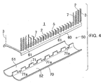
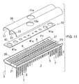
- the upper header member 10 is disposed along the upper end portion of the core 1 along the core width direction, and includes a header plate 20, a header cover 30, a refrigerant distributing resistance plate 41 and an uneven-distribution-flow preventing resistance plate 42.
- a plurality of tube mounting apertures 21 are formed at certain intervals along the longitudinal direction, respectively.
- the header cover 30 is disposed so as to cover the upper surface side of the header plate 20 from the above.
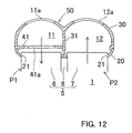
- a partitioning wall 31 is integrally formed so as to extend along the longitudinal direction (the core width direction).
- an outlet-side tank 12 having a tube shape and extending in the core width direction is formed.
- an inlet-side tank 11 having a tube shape and extending in the core width direction is formed.
- a refrigerant inlet 11a is formed at the longitudinal middle portion of the header cover 30 of the inlet-side tank 11, while a refrigerant outlet 12a is formed at the portion of the header cover 30 of the outlet-side tank 12.
- a refrigerant distributing resistance plate 41 is provided so as to divide the inner space into an upper space and a lower space.
- This refrigerant distributing resistance plate 41 is equipped with a plurality of refrigerant passage apertures 41a formed at certain intervals in the longitudinal direction.
- the diameter of the aperture 41a near the refrigerant inlet 11a, or the diameter of the aperture 41a located at the longitudinal central portion is formed to be the smallest, while the diameters of the other apertures 41a are formed to become gradually larger as it goes toward the longitudinal end portion from the longitudinal central portion.
- an uneven-distribution-flow preventing resistance plate 42 is provided so as to divide the inside space into an upper space and a lower space.
- This uneven-distribution-flow preventing resistance plate 42 is provided with a plurality of refrigerant passage apertures 42a, which are the same in diameter, at certain intervals along the longitudinal direction.
- a header cap 15 is attached to each of both end openings of the upper header member 10 so as to air-tightly seal each end opening.
- joint tubes 11b and 12b are fixed so as to communicate with the inlet 11a and outlet 12a.
- the refrigerant distributing resistance plate 41 and the uneven-distribution-flow preventing resistance plate 42 are formed separately to the header plate 20 and the header cover 30.
- these resistance plates 41 and 42 may be integrally formed with the header plate 20 and/or the header cover 30.
- the partitioning wall 31 may be integrally formed with the header plate 20.
- the partitioning wall 31 may be formed as a separate member.
- each of the tube mounting apertures 21 of the header plate 20 constituting the aforementioned upper header member 10 the upper end of each of the heat exchanging tubes 6 and 7 constituting the aforementioned core 1 is fixed in an inserted state.
- the upstream-side heat exchanging tubes 6 are communicated with the inlet-side tank 11, while the downstream-side heat exchanging tubes 7 are communicated with the outlet-side tank 12.
- the lower side header member 50 is disposed at the lower end portion of the core 1 along the core width direction, and has a header plate 60 and a header cover 70.
- the header plate 60 is provided with a plurality of tube mounting apertures 61 arranged at certain intervals in the longitudinal direction thereof at the front half region and the rear half region thereof respectively.
- the header cover 70 is attached to the header plate 60 so as to cover the lower surface of the header plate, and has, at the widthwise middle position on the upper surface thereof, a partitioning wall 71 continuously extending in the longitudinal direction of the header cover (the core width direction).
- This partitioning wall 71 is provided with a plurality of cut-out communication apertures 71a at certain intervals in the longitudinal direction.
- an inflow-side tank 51 having a tube shape and extending in the core width direction is formed.
- an outflow-side tank 52 having a tube shape and extending in the core width direction is formed.
- the inflow-side tank 51 and the outflow-side tank 52 are communicated by the cut-out communication apertures 71a formed in the partitioning wall 71.
- a header cap 55 is attached to each of the end openings of the lower header member 50 in an air-tightly sealed manner.
- the partitioning wall 71 of the lower header member 50 may be integrally formed with the header plate 60 or may be formed as a separate member.
- each heat exchanging tube 6 and 7 is fixed in an inserted manner.
- the upstream-side heat exchanging tube 6 is communicated with the inflow-side tank 51 of the lower header member 50, while the downstream-side heat exchanging tube 7 is communicated with the outflow-side tank 52.
- each component is made of aluminum or its alloy, or an aluminum brazing sheet in which a brazing layer is laminated on at least one surface of the brazing sheet.
- These components are provisionally assembled together with brazing materials if necessary into a predetermined evaporator configuration. Then, this provisionally assembled product is collectively brazed in a furnace to integrally connect the components.
- the method of connecting the components is not specifically limited and may be performed by any known procedure.
- the aforementioned evaporator is mounted as an automobile refrigeration cycle together with a compressor, a condenser and decompressing means such that the front-face side (the downstream-side heat exchanging tube group side P2) and the rear-face side (the upstream-side heat exchanging tube side P1) constitute an air taking-in side and an air taking-out side, respectively.
- mist-like two phase refrigerant including a liquid phase and a vapor phase passed the compressor, the condenser and the decompressing means is introduced into the inlet-side tank 11 of the upper header member 10 via the refrigerant inlet 11a of the aforementioned evaporator.
- the refrigerant introduced into the inlet-side-tank 11 is distributed by the refrigerant distributing resistance plate 41 in the longitudinal direction of the tank 11 and passes through each refrigerant passage aperture 41a of the resistance plate 41.
- the refrigerant tends to pass through the refrigerant passage apertures 41a near the refrigerant inlet 11a, i.e., the refrigerant passage apertures 41a located at the longitudinal middle portion, at a large rate because of the inertia.
- the refrigerant distributes smoothly in the longitudinal direction and passes through each refrigerant passage aperture 41a.
- the refrigerant passage aperture 41a of the resistance plate 41 is formed to be small in diameter at the longitudinal middle portion, while the refrigerant passage aperture 41a is formed to be larger as it goes toward the end portion of the resistance plate 41. Therefore, the volume of refrigerant passing through each refrigerant passage aperture 41a is restricted moderately, and therefore the refrigerant equally passes through each refrigerant passage aperture 41a. This also enables to effectively distribute the refrigerant in the longitudinal direction of the inlet-side tank 10.
- the refrigerant equally distributed by the resistance plate 41 is equally introduced into each tube 6 of the upstream-side heat exchanging tube group P1.
- the refrigerant introduced into the upstream-side heat exchanging tube group P1 is introduced into the inflow-side tank 51 of the lower header member 50 through each tube 6, and then introduced into the outflow-side tank 52 through the cut-out communication apertures 71a of the partitioning wall 71.
- the refrigerant passing through the upstream-side heat exchanging tube group P1 is equally distributed into each heat exchanging tube 6, the refrigerant is equally distributed and introduced into each tube 7 of the downstream-side heat exchanging tube group P2 by passing through the inflow-side tank 51 and the outflow-side tank 52s of the lower header member 50 while keeping the equally distribution state.
- each downstream-side heat exchanging tube 7 is introduced into the outlet-side tank 12 of the upper header member 10.
- the refrigerant receives a moderate flow resistance by the uneven-distribution-flow preventing resistance plate 42, resulting in an equally balanced pressure of refrigerant at the entire longitudinal direction of the outlet-side tank 12, which assuredly prevents uneven-distribution-flow of the refrigerant.
- the refrigerant flows out of the refrigerant outlet 12a via each refrigerant passage aperture 42a of the resistance plate 42.
- the uneven-distribution-flow preventing resistance plate 42 prevents the refrigerant from being unevenly distributed in the outlet-side tank 12, the refrigerant is effectively prevented from being unevenly distributed in the downstream-side heat exchanging tube group P2.
- the refrigerant can pass through each heat exchanging tube 7 at the downstream-side in an evenly distributed manner.
- the refrigerant flowed out of the refrigerant outlet 12a of the upper header member 10 is returned to the compressor in the aforementioned refrigeration cycle.
- the refrigerant passing through the upstream and downstream-side heat exchanging tube groups P1 and P2 absorbs heat from the air A taken from the front-side of the core 1 and evaporates by exchanging heat with the air. Furthermore, the air A cooled by the heat absorption flows out of the rear-side of the core 1, and is sent to the interior of a car.
- the refrigerant passes through each heat exchanging tube 6 and 7 of the upstream-side and downstream-side heat exchanging tube groups P1 and P2 in an equally distributed manner. Therefore, the refrigerant can exchange heat at the entire region of the heat exchanging tube groups P1 and P2, i.e., the entire region of the core 1, resulting in an improved heat exchange performance.
- the refrigerant passes through two tube groups P1 and P2 forming a simple U-shaped refrigerant passage, the refrigerant flow resistance can be decreased.
- the passage cross-sectional area of the refrigerant can be decreased, and therefore the tube height of each heat exchanging tube 6 and 7 can be decreased. Accordingly, the size, weight and thickness can be further decreased.
- the installation number of heat exchanging tubes 6 and 7 can be increased without changing the evaporator size, resulting in further enhanced refrigeration dispersibility, which in turn can further improve the heat exchange performance.
- the partitioning wall 31 disposed between the upper wall and the bottom wall of the upper header member 10 continuously extends within the upper header member 10 in the longitudinal direction
- the partitioning wall 71 disposed between the upper wall and the bottom wall of the lower header member 50 continuously extends within the lower header member 50 in the longitudinal direction. Accordingly, these partitioning walls 31 and 71 reinforce each header member 10 and 50, and therefore both the header members 10 and 50 can be improved in pressure resistance.
- a tubular member 5 which is formed by integrally connecting the corresponding heat exchanging tubes 6 and 7 of the upstream-side heat exchanging tube group P1 and the downstream-side heat exchanging tube group P2 is employed. Therefore, the upstream-side and downstream-side heat exchanging tubes 6 and 7 can be formed by simply laminating the aforementioned tubular members 5. As a result, the evaporator can be fabricated easily. Furthermore, since the heat exchanging tubes 6 and 7 are connected between the heat exchanging tube groups P1 and P2, the strength of the assembly is increased.
- the relation of the tube height H of the heat exchanging tube and the heat exchanging amount ratio % is shown in Fig. 10 .
- the heat exchanging amount ratio is high at the tube height H falling within the range of 0.75 to 1.5 mm. Therefore, a heat exchanging tube of such a tube height is suitably employed.
- the tube height preferably falls within the range of about 1.5 to 3.0 mm which is twice the height of the tube height of the evaporator according to this embodiment.
- the refrigerant distributing resistance plate 41 and the uneven-distribution-flow preventing resistance plate 42 are provided in the inlet-side tank 11 and the outlet-side tank 12 of the upper header member 10, the present invention is not limited to it.
- the uneven-distribution-flow preventing resistance plate 42 may be omitted.
- the refrigerant distributing resistance plate 41 may be omitted, or both of the refrigerant distributing resistance plate 41 and the uneven-distribution-flow preventing resistance plate 42 may be omitted.
- refrigerant inlet 11a and outlet 12a are formed in the longitudinal middle upper portion of the upper header member 10, the present invention is not limited to it.
- refrigerant inlets 11a and 12a may be formed at one end portion of the header member 10 so that the refrigerant can be flowed into and out of the evaporator from the header end portion.
- the refrigerant passage apertures 42a of the uneven-distribution-flow preventing resistance plate 42 may be formed at the windward side of the widthwise middle portion of the tube relative to the air taking-in direction of the evaporator. Furthermore, the refrigerant passage aperture 42a may be formed into a circular shape, or an ellipse shape or a rectangle shape having a major axis along the widthwise direction of the heat exchanging tube.
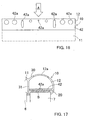
- the cross-sectional area S of the gap (shown by hatching in Fig. 17 ) formed between the resistance plate 42 and the end portion of the heat exchanging tube 7 in the outflow-side tank 12 of the upper side header member 10 is 1 to 5 times of the passage cross-sectional area of the heat exchanging tube 7.
- this structure it is possible to prevent an increase of the flow resistance between the uneven-distribution-flow preventing resistance plate 42 and the tube end portion and secure an appropriate space in the header member.
- an air A is introduced from the downstream-side heat exchanging tube group P2 as an evaporator front side
- the present invention is not limited to it.
- an air A may be introduced from the upstream-side heat exchanging tube group P1 as an evaporator front side.
- the installation direction of the evaporator is not limited to a specific direction, and the evaporator may be installed at any direction.
- Figs. 18 and 19 show an evaporator of a second embodiment of the present invention.
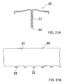
- the header plate 20 and 60 and the header cover 30 and 70 constituting the inlet-and-outlet side (upper side) header member 10 and the refrigerant-turn-side (lower side) header member 50 are formed by a press-formed aluminum (or its alloy) plate respectively.
- the header plate of the upper side header member 10 and 20 is formed by bending an aluminum plate to which perforation press forming is performed.
- a plurality of tube mounting apertures 21 are formed in the header plate 20 in two rows front and rear at certain intervals along the longitudinal direction and a plurality of engaging apertures 22 are formed at certain intervals along the longitudinal direction between the front and rear rows of the tube mounting apertures 21.
- the upper header cover 30 is made of an aluminum plate member which is thinner than a plate member constituting the aforementioned header plate 20, and is formed by subjecting the aluminum plate member to bending processing after the prescribed perforation processing.
- This press forming forms the header cover 30 such that a downwardly protruded partitioning wall 31 formed by folding the widthwise middle portion is formed and downwardly protruded engaging protrusions 32 corresponding to the aforementioned engaging apertures 22 of the header plate 20 are formed at the tip of each partitioning wall 31.
- This header cover 30 is fixed to the header plate 20 in a state that the header cover 30 covers the upper surface side of the header plate 20 and the tip of the engaging protrusion 32 of the partitioning wall 31 is inserted in the engaging aperture 22 of the header plate 20 and caulked.
- the lower side header plate 60 of the lower header member 60 is formed by subjecting an aluminum plate to a perforation processing and bending processing in the same manner as in the aforementioned header plate 10.
- a plurality of tube mounting apertures 61 are formed in the header plate 60 in two rows front and rear at certain intervals along the longitudinal direction and a plurality of engaging apertures 62 are formed at certain intervals along the longitudinal direction between the front and rear rows of the tube mounting apertures 61.
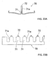
- the lower header cover 70 is made of a thin aluminum plate member formed by subjecting the aluminum plate member to perforation processing and bending processing in the same manner as in the header cover 30.
- This press forming forms the header cover 70 such that an upwardly protruded partitioning wall 71 formed by folding the widthwise middle portion is formed and upwardly protruded engaging protrusions 72 corresponding to the engaging apertures 62 of the header plate 60 are formed at the tip of each partitioning wall 71.
- cut-out communication apertures 71a are formed at certain intervals along the longitudinal direction.
- This header cover 70 is fixed to the header plate 60 in a state that the header cover 70 covers the lower surface side of the header plate 60 and the tip of the engaging protrusion 72 of the partitioning wall 71 is inserted in the engaging aperture 62 of the header plate 60 and caulked.
- an inflow-side tank 51 of a tube shape extending in the core width direction is formed, while at the front-side space of the partitioning wall 71 an outflow-side tank 11 of a tube shape extending in the core width direction is formed.
- the inflow-side tank 51 and the outflow-side tank 52 are communicated with each other via communication apertures 71a formed in the partition 71.
- the evaporator components are provisionally assembled into a predetermined evaporator configuration, and the provisionally assembled product is collectively brazed in a furnace to thereby integrally connect them.
- header structural member 20, 30, 60 and 70 of each header member 10 and 50 can be continuously manufactured from a coiled aluminum member, resulting in an enhanced productivity.
- header structure member 20, 30, 60 and 70 is made of a plate member, a brazing sheet having clad materials such as brazing materials or sacrifice materials laminated on at least one side surface thereof can be used as the header structure member 20, 30, 60 and 70, resulting in an enhanced brazability.
- the corrosion protection nature can bye improved by containing zinc (Zn) into the cladding materials to thereby form a sacrifice material layer.
- the partitioning wall 31 and 71 of both the header members 10 and 50 since the partitioning wall 31 and 71 of both the header members 10 and 50, sufficient strength can be secured while decreasing the header height and the wall thickness, resulting in a reduced size and weight. Especially, since the partitioning wall 31 and 71 is formed by folding a plate member, sufficient strength can be secured even if the thickness is thin, which enables to further decrease the size and weight.
- the refrigerant distributing resistance plate 41 and the uneven-distribution-flow preventing resistance plate 42 may be provided in the header member 10 and 50 in the same manner as in the first embodiment.
- header plate 20 and 60 and the header cover 30 and 70 constituting the header member 10 and 50 are formed by an aluminum plate respectively, in the present invention, a part of these members may be made of an extruded molded article.
- the position of the refrigerant inlet and/or the refrigerant outlet, the air take-in direction and the installation direction of the evaporator are not specifically limited.
- the refrigerant passage is formed into a simple U-shape
- the refrigerant flow resistance can be decreased.
- the refrigerant flow cross-sectional area can be decreased and the tube height of the heat exchanging tube can be decreased. Accordingly, the size, weight and thickness of the evaporator can be reduced.
- the number of tubes can be increased without increasing the core size. Therefore, the refrigerant dispersibility can be improved, resulting in improved heat exchanging performance.
- the header member is made of a metal press-formed plate
- the productivity can be improved and the brazability and corrosion resistance can also be improved by using a brazing sheet.
- the fifth to eighth aspect of the present invention specify a manufacturing process of the evaporator of the first to fourth aspect of the present invention. Therefore, the aforementioned evaporator can be manufactured more assuredly.
- the ninth and tenth aspects of the present invention specify a header member applicable to the evaporator of the third or fourth aspect of the present invention. Therefore, the aforementioned evaporator can be manufactured more assuredly.
- the eleventh to fourteenth aspects of the present invention specify a refrigerant system using the evaporator of the first to fourth aspect of the present invention. Therefore, the aforementioned effects can be obtained more assuredly.
- the evaporator, the manufacturing method thereof, the header member for evaporators and a refrigeration system can improve heat exchanging performance while reducing the size and weight. Therefore, they can be preferably used for a refrigeration cycle for car air-conditioning system especially.
Landscapes
- Engineering & Computer Science (AREA)
- Physics & Mathematics (AREA)
- Thermal Sciences (AREA)
- Mechanical Engineering (AREA)
- General Engineering & Computer Science (AREA)
- Heat-Exchange Devices With Radiators And Conduit Assemblies (AREA)
- Details Of Heat-Exchange And Heat-Transfer (AREA)
- Vaporization, Distillation, Condensation, Sublimation, And Cold Traps (AREA)
Claims (44)
- Verdampfer mit:einem Kern (1), der eine strömungsaufwärtsseitige Wärmetauscherrohrgruppe (6) und eine strömungsabwärtsseitige Wärmetauscherrohrgruppe (7) aufweist, die an einer Vorderseite und an einer Hinterseite angeordnet sind, wobei jede der Wärmetauscherrohrgruppen (6, 7) eine Mehrzahl von Wärmetauscherrohren aufweist, die in bestimmten Abständen parallel zueinander angeordnet sind,einem einlassseitigen Tank (11), der entlang einer Endseite der strömungsaufwärtsseitigen Wärmetauscherrohrgruppe (6) angeordnet ist,einem auslassseitigen Tank (12), der entlang einer Endseite der strömungsabwärtsseitigen Wärmetauscherrohrgruppe (7) angeordnet ist, undeinem Kühlmittel-Wendeelement, das entlang der anderen Endseite beider Wärmetauscherrohrgruppen (6, 7) angeordnet ist,wobei jedes eine Ende der Wärmetauscherrohre, die die strömungsaufwärtsseitige Wärmetauscherrohrgruppe (6) bilden, mit dem einlassseitigen Tank (11) verbunden ist, wohingegen das andere Ende dieser mit dem Kühlmittel-Wendeelement verbunden ist, undwobei jedes eine Ende der Wärmetauscherrohre, die die strömungsabwärtsseitige Wärmetauscherrohrgruppe (7) bilden, mit dem auslassseitigen Tank (12) verbunden ist, wohingegen das andere Ende dieser mit dem Kühlmittel-Wendeelement verbunden ist,wodurch in den einlassseitigen Tank (11) hineingeströmtes Kühlmittel über die strömungsaufwärtsseitige Wärmetauscherrohrgruppe (6), das Kühlmittel-Wendeelement und die strömungsabwärtsseitige Wärmetauscherrohrgruppe (7) in den auslassseitigen Tank (12) eingeleitet wird, wobei das durch beide Wärmetauscherrohrgruppen (6, 7) hindurch passierende Kühlmittel durch Wärmeaustausch mit Umgebungsluft verdampft,dadurch gekennzeichnet, dass der auslassseitige Tank (12) mit Ungleichmäßig-Verteilungsströmung-Verhinderungs-Widerstandsmitteln versehen ist, welche eine Ungleichmäßig-Verteilungsströmung des Kühlmittels verhindern.
- Verdampfer wie in Anspruch 1 definiert, wobei der einlassseitige Tank (11) mit Kühlmittel-Verteilungs-Widerstandsmitteln versehen ist, welche das Kühlmittel in einer Längsrichtung des einlassseitigen Tanks (11) verteilen.
- Verdampfer wie in Anspruch 1 oder 2 definiert, ferner aufweisend:ein Einlass-und-Auslass-Seiten-Sammlerelement (10), das entlang einer Endseite von beiden Wärmetauscherrohrgruppen (6, 7) angeordnet ist, undein Kühlmittel-Wendeseiten-Sammlerelement (50), das entlang der anderen Endseite von beiden Wärmetauscherrohrgruppen (6, 7) angeordnet ist, wobei ein Inneres des Einlass-und-Auslass-Seiten-Sammlerelements (10) vorne und hinten durch eine Trennwand (31) in einen Vorderseitenabschnitt und einen Hinterseitenabschnitt unterteilt ist, wobei der Vorderseitenabschnitt den einlassseitigen Tank (11) bildet und der Hinterseitenabschnitt den auslassseitigen Tank (12) bildet.
- Verdampfer wie in Anspruch 3 aufgeführt, wobei das Einlass-und-Auslass-Seiten-Sammlerelement (10) eine Einlass-und-Auslass-Seiten-Sammlerplatte (20), an der ein Ende von jedem der Wärmetauscherrohre in durchdringender Weise befestigt ist, und eine Einlass-und-Auslass-Seiten-Sammlerabdeckung (30) aufweist, die an der Sammlerplatte (20) angebracht ist, so dass eine Flächenseite der Sammlerplatte (20) abgedeckt ist.
- Verdampfer wie in Anspruch 3 oder 4 aufgeführt, wobei das Kühlmittel-Wendeseiten-Sammlerelement (50) eine Kühlmittel-Wendeseiten-Sammlerplatte (60), an der das andere Ende von jedem der Wärmetauscherrohre in durchdringender Weise befestigt ist, und eine Kühlmittel-Wendeseiten-Sammlerabdeckung (70) aufweist, die an der Sammlerplatte (60) angebracht ist, so dass die andere Fläche der Sammlerplatte (60) abgedeckt ist.
- Verdampfer wie in Anspruch 2 aufgeführt, wobei das Kühlmittel-Verteilungs-Widerstandsmittel eine Kühlmittel-Verteilungs-Widerstandsplatte (41) ist, welche den einlassseitigen Tank (11) in einen oberen Raum und einen unteren Raum unterteilt und welche eine Mehrzahl von Kühlmittelpassagen-Öffnungen (41a) aufweist, die in Abständen entlang der Längsrichtung des einlassseitigen Tanks (11) ausgebildet sind.
- Verdampfer wie in Anspruch 6 aufgeführt, wobei die Mehrzahl von Kühlmittelpassagen-Öffnungen (41a) der Kühlmittel-Verteilungs-Widerstandsplatte (41) in der Größe unterschiedliche Öffnungen (41a) aufweisen.
- Verdampfer wie in Anspruch 7 aufgeführt, wobei das Einlass-und-Auslass-Seiten-Sammlerelement (10) einen Kühlmitteleinlass (11a) aufweist zum Einleiten von Kühlmittel in den einlassseitigen Tank (11) hinein, und wobei die Mehrzahl von Kühlmittelpassagen-Öffnungen (41a) der Kühlmittel-Verteilungs-Widerstandsplatte (41) so ausgebildet sind, dass die Kühlmittelpassagen-Öffnung (41a) in der Größe zunimmt, wie sie sich von dem Kühlmitteleinlass (11a) entfernt.
- Verdampfer wie in Anspruch 8 aufgeführt, wobei der Kühlmitteleinlass (11a) an einer Längsmittelposition des einlassseitigen Tanks (11) ausgebildet ist, und wobei die Kühlmittelpassagen-Öffnungen (41a), die in der Kühlmittel-Verteilungs-Widerstandsplatte (41) ausgebildet sind und die entfernt von dem Kühlmitteleinlass (11a) angeordnet sind, so ausgebildet sind, dass sie eine Größe aufweisen, die größer als eine Größe der Kühlmittelpassagen-Öffnung (41a) ist, die in der Nähe des Kühlmitteleinlasses (11a) angeordnet ist.
- Verdampfer wie in Anspruch 8 aufgeführt, wobei der Kühlmitteleinlass (11a) an einem Längsendabschnitt des einlassseitigen Tanks (11) vorgesehen ist.
- Verdampfer wie in Anspruch 1 aufgeführt, wobei das Ungleichmäßig-Verteilungsströmung-Verhinderungs-Widerstandsmittel eine Ungleichmäßig-Verteilungsströmung-Verhinderungs-Widerstandsplatte (42) ist, welche den auslassseitigen Tank (12) in einen oberen Raum und einen unteren Raum unterteilt und welche eine Mehrzahl von Kühlmittelpassagen-Öffnungen (42a) aufweist, die in Abständen entlang einer Längsrichtung des auslassseitigen Tanks (12) ausgebildet sind.
- Verdampfer wie in Anspruch 11 aufgeführt, wobei eine Distanz zwischen benachbarten, in der Ungleichmäßig-Verteilungsströmung-Verhinderungs-Widerstandsplatte (42) ausgebildeten Kühlmittelpassagen-Öffnungen (42a) in den Bereich von 1 bis 4 mal so lang wie eine Distanz zwischen benachbarten Wärmetauscherrohren fällt.
- Verdampfer wie in Anspruch 11 aufgeführt, wobei die Kühlmittelpassagen-Öffnungen (42a), die in der Ungleichmäßig-Verteilungsströmung-Verhinderungs-Widerstandsplatte (42) ausgebildet sind, in Bezug auf eine Lufteinlassrichtung aus einem breitenmäßigen Mittelabschnitt des Wärmetauscherrohres in Richtung zu einer Windseite hin versetzt sind.
- Verdampfer wie in Anspruch 11 aufgeführt, wobei das Einlass-und-Auslass-Seiten-Sammlerelement (10) einen Kühlmittelauslass (12a) aufweist, durch welchen hindurch Kühlmittel aus dem auslassseitigen Tank (12) herausströmt, und wobei eine Querschnittsfläche einer Kühlmittelpassagen-Öffnung (42a), die unter den in der Ungleichmäßig-Verteilungsströmung-Verhinderungs-Widerstandsplatte ausgebildeten Kühlmittelpassagen-Öffnungen (42a) an der entferntesten Position von dem Kühlmittelauslass angeordnet ist, auf 7mm2 oder weniger konfiguriert ist.
- Verdampfer wie in Anspruch 14 aufgeführt, wobei der Kühlmittelauslass (12a) an einem Längsmittelabschnitt des auslassseitigen Tanks (12) vorgesehen ist.
- Verdampfer wie in Anspruch 14 aufgeführt, wobei der Kühlmittelauslass (12a) an einem Längsendabschnitt des auslassseitigen Tanks (12) vorgesehen ist.
- Verdampfer wie in Anspruch 11 aufgeführt, wobei eine Querschnittsfläche zwischen der Ungleichmäßig-Verteilungsströmung-Verhinderungs-Widerstandsplatte (42) und einem Endabschnitt des Wärmetauscherrohres in dem auslassseitigen Tank (12) 1 bis 5 mal so groß wie eine Passagenquerschnittsfläche des Wärmetauscherrohres ist.
- Verdampfer wie in Anspruch 11 aufgeführt, wobei eine Gesamtquerschnittsfläche der in der Ungleichmäßig-Verteilungsströmung-Verhinderungs-Widerstandsplatte (42) ausgebildeten Kühlmittelpassagen-Öffnungen (42a) größer als eine Gesamt-Passagenquerschnittsfläche der Wärmetauscherrohre in der strömungsabwärtsseitigen Wärmetauscherrohrgruppe (7) ist.
- Verdampfer wie in Anspruch 11 aufgeführt, wobei jede der in der Ungleichmäßig-Verteilungsströmung-Verhinderungs-Widerstandsplatte (42) ausgebildeten Kühlmittelpassagen-Öffnungen (42a) in einer runden Form ausgebildet ist.
- Verdampfer wie in Anspruch 11 aufgeführt, wobei die in der Ungleichmäßig-Verteilungsströmung-Verhinderungs-Widerstandsplatte (42) ausgebildete Kühlmittelpassagen-Öffnung (42a) in einer Ellipsenform oder in einer Rechteckform mit einer großen Achse entlang einer Breitenrichtung des Wärmetauscherrohres ausgebildet ist.
- Verdampfer wie in einem der Ansprüche 1 bis 6 aufgeführt, wobei korrespondierende Wärmetauscherrohre von beiden Wärmetauscherrohrgruppen (6, 7) integral verbunden sind.
- Verdampfer wie in einem der Ansprüche 1 bis 6 aufgeführt, wobei das Wärmetauscherrohr ein durch Strangpressen erzieltes stranggepresstes Rohr ist.
- Verdampfer wie in einem der Ansprüche 1 bis 6 aufgeführt, wobei eine Rohrhöhe des Wärmetauscherrohres in den Bereich von 0,75 bis 1,5 fällt.
- Verdampfer wie in Anspruch 3 definiert, wobei das Kühlmittel-Wendeseiten-Sammlerelement (50) wenigstens zwei pressgeformte Metallplattenelemente (60, 70) aufweist,
wobei ein Inneres des Kühlmittel-Wendeseiten-Sammlerelements (50) durch eine Kühlmittel-Wendeseiten-Trennwand (71) in einen einströmseitigen Tank (51) und einen ausströmseitigen Tank (52) unterteilt ist, und wobei beide Tanks (51, 52) durch in der Trennwand (71) vorgesehene Verbindungsöffnungen (71a) miteinander in Verbindung stehen,
wobei das andere Ende der Wärmetauscherrohre, die die strömungsaufwärtsseitige Wärmetauscherrohrgruppe (6) bilden, mit dem einströmseitigen Tank (51) des Kühlmittel-Wendeseiten-Sammlerelements (50) verbunden ist, und
wobei das andere Ende der Wärmetauscherrohre, die die strömungsabwärtsseitige Wärmetauscherrohrgruppe (7) bilden, mit dem ausströmseitigen Tank (52) des Kühlmittel-Wendeseiten-Sammlerelements (50) verbunden ist,
wodurch in den einlassseitigen Tank (11) eingeströmtes Kühlmittel über die strömungsaufwärtsseitige Wärmetauscherrohrgruppe (6), den einströmseitigen Tank (51), die Öffnungen (71a), den ausströmseitigen Tank (52) und die strömungsabwärtsseitige Wärmetauscherrohrgruppe (7) in den auslassseitigen Tank (12) eingeleitet wird. - Verdampfer wie in Anspruch 24 aufgeführt, wobei das Kühlmittel-Wendeseiten-Sammlerelement (50) eine Sammlerplatte (60), an der ein Ende von jedem der Wärmetauscherrohre in durchdringender Weise befestigt ist, und eine Sammlerabdeckung (70) aufweist, die an der Sammlerplatte (60) angebracht ist, so dass eine Flächenseite der Sammlerplatte (60) abgedeckt ist, und wobei die Kühlmittel-Wendeseiten-Trennwand (71) geformt ist durch Falten eines breitenmäßigen Mittelabschnitts eines die Sammlerabdeckung (70) bildenden Metallplattenelements entlang einer Längsrichtung dessen.
- Verdampfer wie in Anspruch 25 aufgeführt, wobei die Kühlmittel-Wendeseiten-Trennwand (71) an einem äußersten Endabschnitt dieser in bestimmten Abständen entlang einer Längsrichtung dieser Eingriffsabschnitte (72) aufweist, wobei die Sammlerplatte (60) an einem breitenmäßigen Mittelabschnitt dieser in bestimmten Abständen entlang einer Längsrichtung dieser zu den Eingriffsvorsprüngen (72) korrespondierende Eingriffsöffnungen (62) aufweist, und wobei die Eingriffsvorsprünge (72) in die Eingriffsöffnungen (62) eingesetzt und durch eine Verstemmbearbeitung befestigt sind.
- Verdampfer wie in Anspruch 24 aufgeführt, wobei das das Kühlmittel-Wendeseiten-Sammlerelement (50) bildende Metallplattenelement von einem Aluminium-Hartlöt-Blech mit einem Aluminiumkern und einer auf wenigstens eine Seite des Kerns auflaminierten Hartlötschicht geformt ist.
- Verdampfer wie in Anspruch 27 aufgeführt, wobei das Hartlöt-Blech eine auf eine äußere Flächenseite dessen auflaminierte Hartlötschicht aufweist, und wobei die Hartlötschicht Zink enthält.
- Verdampfer wie in Anspruch 25 aufgeführt, wobei eine Dickenabmessung der Sammlerabdeckung (70) dünner als jene der Sammlerplatte (60) ist.
- Verdampfer wie in Anspruch 24 aufgeführt wobei das Einlass-und-Auslass-Seiten-Sammlerelement (10) wenigstens zwei pressgeformte Metallplattenelemente (20, 30) aufweist.
- Verdampfer wie in Anspruch 30 aufgeführt, wobei das Einlass-und-Auslass-Seiten-Sammlerelement (10) eine Sammlerplatte (20), an der ein Endabschnitt von jedem der Tauscherrohre in durchdringender Weise befestigt ist, und eine Sammlerabdeckung (30) aufweist, die an der Sammlerplatte (20) angebracht ist, so dass eine Flächenseite dieser abgedeckt ist, und wobei die Einlass-und-Auslass-Seiten-Trennwand (31) geformt ist durch Falten eines breitenmäßigen Mittelabschnitts eines die Sammlerabdeckung (30) bildenden Metallplattenelements entlang einer Längsrichtung dessen.
- Verdampfer wie in Anspruch 31 aufgeführt, wobei die Einlass-und-Auslass-Seiten-Trennwand (31) an einem äußersten Endabschnitt dieser in bestimmten Abständen entlang einer Längsrichtung dieser Eingriffsvorsprünge (32) aufweist, wobei die Sammlerplatte (20) an einem breitenmäßigen Mittelabschnitt dieser in bestimmten Abständen entlang einer Längsrichtung dieser zu den Eingriffsvorsprüngen (32) korrespondierende Eingriffsöffnungen (22) aufweist, und wobei die Eingriffsvorsprünge (32) in die Eingriffsöffnungen (22) eingesetzt sind und durch eine Verstemmbearbeitung befestigt sind.
- Verdampfer wie in Anspruch 30 aufgeführt, wobei das das Einlass-und-Auslass-Seiten-Sammlerelement (10) bildende Metallplattenelement von einem Aluminium-Hartlöt-Blech mit einer auf wenigstens eine Seite dessen auflaminierten Hartlötschicht geformt ist.
- Verdampfer wie in Anspruch 33 aufgeführt, wobei das Hartlöt-Blech die Hartlötschicht auf eine äußere Flächenseite dessen auflaminiert hat, und wobei die Hartlötschicht Zink enthält.
- Verdampfer wie in Anspruch 31 aufgeführt, wobei eine Dickenabmessung der Sammlerabdeckung dünner als jene der Sammlerplatte ist.
- Verdampfer wie in Anspruch 3 definiert, wobei das Einlass-und-Auslass-Seiten-Sammlerelement (10) eine Einlass-und-Auslass-Seiten-Sammlerplatte (20) und eine Einlass-und-Auslass-Seiten-Sammlerabdeckung (30) aufweist, die an der Sammlerplatte (20) angebracht ist, so dass eine Flächenseite der Sammlerplatte (10) abgedeckt ist,
wobei das Kühlmittel-Wendeseiten-Sammlerelement (50) eine Kühlmittel-Wendeseiten-Sammlerplatte (60) und eine Kühlmittel-Wendeseiten-Sammlerabdeckung (70) aufweist, die an der Sammlerplatte (60) angebracht ist, so dass eine Flächenseite der Sammlerplatte (60) abgedeckt ist, wobei eine von der Kühlmittel-Wendeseiten-Sammlerplatte (50) und der Kühlmittel-Wendeseiten-Sammlerabdeckung (70) von einem pressgeformten Metallplattenelement gebildet ist, und wobei das andere dieser von einem stranggepressten geformten Gegenstand gebildet ist,
wobei ein Ende von jedem der Wärmetauscherrohre, die die strömungsaufwärtsseitige Wärmetauscherrohrgruppe (6) bilden, in durchdringender Weise an der Einlass-und-Auslass-Seiten-Sammlerplatte (20) befestigt ist, so dass es dadurch mit dem einlassseitigen Tank (11) verbunden ist, wohingegen das andere Ende dieser in durchdringender Weise mit der Kühlmittel-Wendeseiten-Sammlerplatte (60) verbunden ist,
wobei ein Ende von jedem der Wärmetauscherrohre, die die strömungsabwärtsseitige Wärmetauscherrohrgruppe (7) bilden, an dem Einlass-und-Auslass-Seiten-Sammlerelement (10) befestigt ist, so dass es dadurch mit dem auslassseitigen Tank (12) verbunden ist, wohingegen das andere Ende dieser in vorbestimmter Weise mit dem Kühlmittel-Wendeseiten-Sammlerelement (50) verbunden ist. - Verdampfer wie in Anspruch 36 aufgeführt, wobei eine von der Einlass-und-Auslass-Seiten-Sammlerplatte (20) und der Einlass-und-Auslass-Seiten-Sammlerabdeckung (30) von einem pressgeformten Metallplattenelement gebildet ist und die andere dieser von einem stranggepressten geformten Gegenstand gebildet ist.
- Verfahren zum Herstellen eines Verdampfers, wobei das Verfahren die Schritte aufweist:einen Schritt des Bereitstellens einer Mehrzahl von einer strömungsaufwärtsseitigen Wärmetauscherrohrgruppe (6) und einer strömungsabwärtsseitigen Wärmetauscherrohrgruppe (7) bildenden Wärmetauscherrohren, so dass sie vorne und hinten angeordnet sind,einen Schritt des Bereitstellens eines einlassseitigen Tanks (11), so dass er entlang einer Endseite der strömungsaufwärtsseitigen Wärmetauscherrohrgruppe (6) angeordnet ist,einen Schritt des Bereitstellens eines auslassseitigen Tanks (12), so dass er entlang einer Endseite der strömungsabwärtsseitigen Wärmetauscherrohrgruppe (7) angeordnet ist,einen Schritt des Bereitstellens eines Kühlmittel-Wendeelements, so dass es entlang der anderen Endseite von beiden Wärmetauscherrohrgruppen angeordnet ist,einen Schritt des Hartverlötens von einem Ende von jedem der die die strömungsaufwärtsseitige Wärmetauscherrohrgruppe (6) bildenden Wärmetauscherrohre mit dem einlassseitigen Tank (11),einen Schritt des Hartverlötens des anderen Endes von jedem der die strömungsaufwärtsseitige Wärmetauscherrohrgruppe (6) bildenden Wärmetauscherrohre mit dem Kühlmittel-Wendeelement,einen Schritt des Hartverlötens von einem Ende von jedem der die strömungsabwärtsseitige Wärmetauscherrohrgruppe (7) bildenden Wärmetauscherrohre mit dem auslassseitigen Tank (12), undeinem Schritt des Hartverlötens des anderen Endes von jedem der die strömungsabwärtsseitige Wärmetauscherrohrgruppe (7) bildenden Wärmetauscherrohre mit dem Kühlmittel-Wendeelement,wobei in den einlassseitigen Tank (11) eingeströmtes Kühlmittel mittels Passierens durch die strömungsaufwärtsseitige Wärmetauscherrohrgruppe (6), das Kühlmittel-Wendeelement und die strömungsabwärtsseitige Wärmetauscherrohrgruppe (7) hindurch in den auslassseitigen Tank (12) eingeleitet wird, und wobei das durch beide Wärmetauscherrohrgruppen (6, 7) hindurch passierende Kühlmittel einen Kühlmittelkreislauf bildet, in dem das Kühlmittel durch Wärmeaustausch mit Umgebungsluft verdampft,und wobei der auslassseitige Tank (12) mit Ungleichmäßig-Verteilungsströmung-Verhinderungs-Widerstandsmitteln versehen ist, welche eine Ungleichmäßig-Verteilungsströmung des Kühlmittels verhindern.
- Verfahren zum Herstellen eines Verdampfers wie in Anspruch 38 aufgeführt, wobei das Verfahren ferner die Schritte aufweist:einen Schritt des Bereitstellens eines Einlass-und-Auslass-Seiten-Sammlerelements (10), so dass es entlang einer Endseite von beiden Wärmetauscherrohrgruppen (6, 7) angeordnet ist, wobei ein Inneres des Sammlerelements (10) durch eine Trennwand (31) vorne und hinten in einen Raum der einen Seite, der den einlassseitigen Tank (11) bildet, und einen Raum der anderen Seite unterteilt ist, der den auslassseitigen Tank (12) bildet, undeinen Schritt des Bereitstellens eines Kühlmittel-Wendeseiten-Sammlerelements (70) als ein Kühlmittel-Wendeelement, so dass es entlang der anderen Endseite von beiden Wärmetauscherrohrgruppen (6, 7) angeordnet ist.
- Verfahren zum Herstellen eines Verdampfers wie in Anspruch 38 aufgeführt, wobei das Verfahren ferner die Schritte aufweist:einen Schritt des Bereitstellens eines Einlass-und-Auslass-Seiten-Sammlerelements (10), so dass es entlang eines Endes von beiden Wärmetauscherrohrgruppen (6, 7) angeordnet ist,wobei ein Inneres des Sammlerelements in den einlassseitigen Tank (11) und den auslassseitigen Tank (12) unterteilt ist,einen Schritt des Bereitstellens eines Kühlmittel-Wendeseiten-Sammlerelements (50) als ein Kühlmittel-Wendeseiten-Element, so dass es entlang der anderen Endseite von beiden Wärmetauscherrohrgruppen (6, 7) angeordnet ist, wobei das Kühlmittel-Wendeseiten-Sammlerelement (50) wenigstens zwei pressgeformte Metallplattenelemente (60, 70) aufweist, und wobei ein Inneres des Sammlerelements durch eine Kühlmittel-Wendeseiten-Trennwand (71) in einen einströmseitigen Tank (51) und einen ausströmseitigen Tank (52) unterteilt ist, undwobei beide Tanks (51, 52) über in der Trennwand (71) ausgebildete Verbindungsöffnungen (71a) miteinander in Verbindung stehen,einen Schritt des Hartverlötens des anderen Endes von jedem der die strömungsaufwärtsseitige Wärmetauscherrohrgruppe (6) bildenden Wärmetauscherrohre mit dem einströmseitigen Tank (51) des Kühlmittel-Wendeseiten-Sammlerelements (50), undeinen Schritt des Hartverlötens des anderen Endes von jedem der die strömungsabwärtsseitige Wärmetauscherrohrgruppe (7) bildenden Wärmetauscherrohre mit dem ausströmseitigen Tank (52) des Kühlmittel-Wendeseiten-Sammlerelements (50),wobei in den einlassseitigen Tank (11) eingeströmtes Kühlmittel mittels Passierens durch die strömungsaufwärtsseitige Wärmetauscherrohrgruppe (6), den einströmseitigen Tank (51), die Verbindungsöffnungen (71a), den ausströmseitigen Tank (12) und die strömungsabwärtsseitige Wärmetauscherrohrgruppe (7) hindurch in den auslassseitigen Tank (12) eingeleitet wird.
- Verfahren zum Herstellen eines Verdampfers wie in Anspruch 38 aufgeführt, wobei das Verfahren ferner die Schritte aufweist:einen Schritt des Bereitstellens eines Einlass-und-Auslass-Seiten-Sammlerelements (10), so dass es entlang eines Endes von beiden Wärmetauscherrohrgruppen angeordnet ist, wobei das Sammlerelement (10) eine Einlass-und-Auslass-Seiten-Sammlerplatte (20), eine Einlass-und-Auslass-Seiten-Sammlerabdeckung (30), die an der Sammlerplatte (10) angebracht ist, so dass eine Flächenseite dieser abgedeckt ist, und eine Trennwand (31) aufweist zum Unterteilen eines Inneren des Einlass-und-Auslass-Seiten-Sammlerelements (10) in den einlassseitigen Tank (11) und den auslassseitigen Tank (12),einen Schritt des Bereitstellens eines Kühlmittel-Wendeseiten-Sammlerelements (50) als Kühlmittel-Wendeseiten-Element, so dass es entlang der anderen Endseite von beiden Wärmetauscherrohrgruppen (6, 7) angeordnet ist, wobei das Kühlmittel-Wendeseiten-Sammlerelement (50) eine Kühlmittel-Wendeseiten-Sammlerplatte (60) und eine Kühlmittel-Wendeseiten-Sammlerabdeckung (70) aufweist, die an der Sammlerplatte (60) angebracht ist, so dass eine Seitenfläche dieser abgedeckt ist, wobei eine von der Kühlmittel-Wendeseiten-Sammlerplatte (60) und der Kühlmittel-Wendeseiten-Sammlerabdeckung (70) aus einer pressgeformten Metallplatte hergestellt ist und die andere dieser aus einem stranggepressten geformten Gegenstand hergestellt ist,eine Schritt des Hartverlötens eines Endes von jedem der die strömungsaufwärtsseitige Wärmetauscherrohrgruppe (6) bildenden Wärmetauscherrohre mit der Sammlerplatte (20) des Einlass-und-Auslass-Seiten-Sammlers (10), so dass es dadurch mit dem einlassseitigen Tank (11) verbunden ist,einen Schritt des Hartverlötens des anderen Endes von jedem der die strömungsaufwärtsseitige Wärmetauscherrohrgruppe (6) bildenden Wärmetauscherrohre mit der Sammlerplatte (60) des Kühlmittel-Wendeseiten-Sammlerelements (50),einen Schritt des Hartverlötens eines Endes von jedem der die strömungsabwärtsseitige Wärmetauscherrohrgruppe (7) bildenden Wärmetauscherrohre mit der Sammlerplatte (20) des Einlass-und-Auslass-Seiten-Sammlers (10), so dass es dadurch mit dem auslassseitigen Tank (12) verbunden ist, undeinen Schritt des Hartverlötens des anderen Endes von jedem der die strömungsabwärtsseitige Wärmetauscherrohrgruppe (7) bildenden Wärmetauscherrohre mit der Sammlerplatte (60) des Kühlmittel-Wendeseiten-Sammlerelements (50).
- Verfahren zum Herstellen eines Verdampfers wie in einem der Ansprüche 38-41 aufgeführt, wobei die Hartlötschritte gemeinsam durch eine Ofenhartlötbearbeitung durchgeführt werden.
- Verfahren zum Herstellen eines Verdampfers wie in Anspruch 42 aufgeführt, ferner aufweisend einen Schritt des Ausbildens einer Zinkdiffusionsschicht auf einer Oberfläche von jedem der Sammlerelemente durch Aufbringen eines Zink enthaltenden Fließmittels auf die Oberfläche vor dem Durchführen der Ofenhartlötbearbeitung.
- Kühlsystem, bei dem von einem Kompressor verdichtetes Kühlmittel mittels eines Kondensators zu einem kondensierten Kühlmittel kondensiert wird, dann das kondensierte Kühlmittel durch eine Dekompressionsvorrichtung hindurch zu einem dekomprimierten Kühlmittel überführt wird, und danach das dekomprimierte Kühlmittel mittels eines Verdampfers verdampft wird und dann zu dem Kompressor zurückkehrt, wobei der Verdampfer ein Verdampfer gemäß einem der Ansprüche 1-37 ist.
Applications Claiming Priority (5)
| Application Number | Priority Date | Filing Date | Title |
|---|---|---|---|
| JP2001183062 | 2001-06-18 | ||
| JP2001183062 | 2001-06-18 | ||
| US30314501P | 2001-07-06 | 2001-07-06 | |
| US303145P | 2001-07-06 | ||
| PCT/JP2002/006046 WO2002103263A1 (en) | 2001-06-18 | 2002-06-17 | Evaporator, manufacturing method of the same, header for evaporator and refrigeration system |
Publications (3)
| Publication Number | Publication Date |
|---|---|
| EP1397623A1 EP1397623A1 (de) | 2004-03-17 |
| EP1397623A4 EP1397623A4 (de) | 2006-06-14 |
| EP1397623B1 true EP1397623B1 (de) | 2009-01-28 |
Family
ID=26617087
Family Applications (1)
| Application Number | Title | Priority Date | Filing Date |
|---|---|---|---|
| EP02733504A Expired - Lifetime EP1397623B1 (de) | 2001-06-18 | 2002-06-17 | Verdampfer, herstellungsverfahren dafür, sammler für verdampfer und kühlsystem |
Country Status (11)
| Country | Link |
|---|---|
| US (2) | US7066243B2 (de) |
| EP (1) | EP1397623B1 (de) |
| KR (1) | KR20040012939A (de) |
| CN (1) | CN1277089C (de) |
| AT (1) | ATE422038T1 (de) |
| AU (1) | AU2002304250B2 (de) |
| BR (1) | BR0210482A (de) |
| CZ (1) | CZ20033356A3 (de) |
| DE (1) | DE60231038D1 (de) |
| TW (1) | TW552382B (de) |
| WO (1) | WO2002103263A1 (de) |
Cited By (2)
| Publication number | Priority date | Publication date | Assignee | Title |
|---|---|---|---|---|
| DE102009041011A1 (de) * | 2009-08-05 | 2011-02-17 | Liebherr-Hausgeräte Ochsenhausen GmbH | Verdampfer sowie Kühl- und/oder Gefriergerät |
| US10126028B2 (en) | 2014-09-08 | 2018-11-13 | Mitsubishi Heavy Industries Thermal Systems, Ltd. | Turbo chiller |
Families Citing this family (132)
| Publication number | Priority date | Publication date | Assignee | Title |
|---|---|---|---|---|
| JP4770474B2 (ja) | 2006-01-20 | 2011-09-14 | 株式会社デンソー | エジェクタ式冷凍サイクル用ユニットおよびその製造方法 |
| CN100368752C (zh) * | 2001-12-21 | 2008-02-13 | 贝洱两合公司 | 用于汽车的热交换器 |
| US6814136B2 (en) | 2002-08-06 | 2004-11-09 | Visteon Global Technologies, Inc. | Perforated tube flow distributor |
| EP1447636A1 (de) * | 2003-02-11 | 2004-08-18 | Delphi Technologies, Inc. | Wärmetauscher |
| CN100541107C (zh) * | 2003-02-25 | 2009-09-16 | 林德股份公司 | 热交换器 |
| JP4124136B2 (ja) | 2003-04-21 | 2008-07-23 | 株式会社デンソー | 冷媒蒸発器 |
| JP4248931B2 (ja) * | 2003-05-20 | 2009-04-02 | カルソニックカンセイ株式会社 | 熱交換器 |
| FR2858683B1 (fr) * | 2003-08-07 | 2005-11-04 | Framatome Anp | Echangeur de chaleur et en particulier generateur de vapeur a fond convexe |
| JP2005164125A (ja) * | 2003-12-02 | 2005-06-23 | Denso Corp | 熱交換器 |
| US7775067B2 (en) * | 2004-03-17 | 2010-08-17 | Showa Denko K.K. | Heat exchanger header tank and heat exchanger comprising same |
| US8002024B2 (en) * | 2004-03-23 | 2011-08-23 | Showa Denko K. K. | Heat exchanger with inlet having a guide |
| EP1582834B1 (de) | 2004-04-02 | 2010-10-06 | Calsonic Kansei Corporation | Verdampfer |
| JP4120611B2 (ja) * | 2004-04-08 | 2008-07-16 | 株式会社デンソー | 冷媒蒸発器 |
| JP2005326135A (ja) * | 2004-04-12 | 2005-11-24 | Showa Denko Kk | 熱交換器 |
| KR100590658B1 (ko) * | 2004-04-28 | 2006-06-19 | 모딘코리아 유한회사 | 자동차용 증발기의 헤더 파이프 |
| WO2005108899A1 (en) * | 2004-05-11 | 2005-11-17 | Showa Denko K.K. | Heat exchangers |
| JP4281634B2 (ja) * | 2004-06-28 | 2009-06-17 | 株式会社デンソー | 冷媒蒸発器 |
| CN1981176B (zh) * | 2004-07-05 | 2010-06-16 | 昭和电工株式会社 | 换热器 |
| DE102004036020A1 (de) * | 2004-07-23 | 2006-02-16 | Behr Gmbh & Co. Kg | Wärmeübertrager, insbesondere Kondensator |
| KR100913141B1 (ko) * | 2004-09-15 | 2009-08-19 | 삼성전자주식회사 | 마이크로채널튜브를 이용한 증발기 |
| DE102004056790A1 (de) * | 2004-10-04 | 2006-04-06 | Behr Gmbh & Co. Kg | Wärmetauscher |
| DE112005002755T5 (de) * | 2004-11-30 | 2007-11-08 | Showa Denko K.K., Minato-ku | Wärmetauscher |
| US7303003B2 (en) * | 2004-12-24 | 2007-12-04 | Showa Denko K.K. | Heat exchanger |
| JP2006183962A (ja) * | 2004-12-28 | 2006-07-13 | Denso Corp | 蒸発器 |
| WO2006070918A1 (en) * | 2004-12-28 | 2006-07-06 | Showa Denko K.K. | Evaporator |
| WO2006078048A1 (en) | 2005-01-18 | 2006-07-27 | Showa Denko K.K. | Heat exchanger |
| US7918266B2 (en) * | 2005-03-29 | 2011-04-05 | Showa Denko K.K. | Heat exchanger |
| US7275394B2 (en) | 2005-04-22 | 2007-10-02 | Visteon Global Technologies, Inc. | Heat exchanger having a distributer plate |
| EP1899589B1 (de) * | 2005-06-03 | 2012-08-15 | Behr GmbH & Co. KG | Ladeluftkühler |
| US7784530B2 (en) * | 2005-09-01 | 2010-08-31 | Showa Denko K.K. | Heat exchanger |
| KR100682269B1 (ko) * | 2005-10-05 | 2007-02-15 | 엘지전자 주식회사 | 열교환기 유닛 및 이를 구비한 공기조화장치 |
| EP1777480B1 (de) * | 2005-10-19 | 2018-11-28 | MAHLE Behr GmbH & Co. KG | Wärmeübertrager |
| FR2894021B1 (fr) * | 2005-11-30 | 2008-02-01 | Valeo Systemes Thermiques | Boite collectrice pour echangeur de chaleur, en particulier pour un evaporateur de climatisation |
| DE102005058769B4 (de) * | 2005-12-09 | 2016-11-03 | Modine Manufacturing Co. | Ladeluftkühler |
| JP4692295B2 (ja) * | 2006-01-19 | 2011-06-01 | 株式会社デンソー | 蒸発器ユニットおよびエジェクタ式冷凍サイクル |
| JP4548350B2 (ja) * | 2006-01-20 | 2010-09-22 | 株式会社デンソー | エジェクタ式冷凍サイクル用ユニット |
| JP2008020098A (ja) * | 2006-07-11 | 2008-01-31 | Showa Denko Kk | 熱交換器 |
| US20080023183A1 (en) * | 2006-07-25 | 2008-01-31 | Henry Earl Beamer | Heat exchanger assembly |
| US20080023184A1 (en) * | 2006-07-25 | 2008-01-31 | Henry Earl Beamer | Heat exchanger assembly |
| US7484555B2 (en) * | 2006-07-25 | 2009-02-03 | Delphi Technologies, Inc. | Heat exchanger assembly |
| US20080023185A1 (en) * | 2006-07-25 | 2008-01-31 | Henry Earl Beamer | Heat exchanger assembly |
| US20100270012A1 (en) * | 2006-09-25 | 2010-10-28 | Korea Delphi Automotive Systems Corporation | Automotive heat exchanger to the unification of header and tank and fabricating method thereof |
| ES2387134T3 (es) * | 2006-10-13 | 2012-09-14 | Carrier Corporation | Intercambiadores de calor multipasos que tienen colectores de retorno con insertos de distribución |
| WO2008045111A1 (en) * | 2006-10-13 | 2008-04-17 | Carrier Corporation | Multi-channel heat exchanger with multi-stage expansion device |
| WO2008064247A1 (en) * | 2006-11-22 | 2008-05-29 | Johnson Controls Technology Company | Multi-function multichannel heat exchanger |
| WO2008064219A1 (en) * | 2006-11-22 | 2008-05-29 | Johnson Controls Technology Company | Multichannel evaporator with flow mixing manifold |
| WO2008064251A2 (en) * | 2006-11-22 | 2008-05-29 | Johnson Controls Technology Company | Space-saving multichannel heat exchanger |
| WO2008073111A1 (en) * | 2006-12-15 | 2008-06-19 | Carrier Corporation | Refrigerant vapor injection for distribution improvement in parallel flow heat exchanger manifolds |
| WO2008079135A1 (en) * | 2006-12-26 | 2008-07-03 | Carrier Corporation | Heat exchanger design for improved performance and manufacturability |
| JP5002797B2 (ja) * | 2007-03-16 | 2012-08-15 | 株式会社ケーヒン・サーマル・テクノロジー | 熱交換器 |
| JP5114771B2 (ja) * | 2007-05-29 | 2013-01-09 | 株式会社ケーヒン・サーマル・テクノロジー | 熱交換器 |
| US8166776B2 (en) * | 2007-07-27 | 2012-05-01 | Johnson Controls Technology Company | Multichannel heat exchanger |
| US20090025405A1 (en) * | 2007-07-27 | 2009-01-29 | Johnson Controls Technology Company | Economized Vapor Compression Circuit |
| JP5046771B2 (ja) * | 2007-07-27 | 2012-10-10 | 三菱重工業株式会社 | 冷媒蒸発器 |
| US7942020B2 (en) | 2007-07-27 | 2011-05-17 | Johnson Controls Technology Company | Multi-slab multichannel heat exchanger |
| EP2193315B1 (de) * | 2007-08-24 | 2011-10-12 | Johnson Controls Technology Company | Dampfkompressionsanlage und steuerungsverfahren dafür |
| US8081462B2 (en) * | 2007-09-13 | 2011-12-20 | Rockwell Automation Technologies, Inc. | Modular liquid cooling system |
| DE102008052331A1 (de) * | 2007-10-24 | 2009-06-10 | Denso Corp., Kariya-shi | Verdampfereinheit |
| US8353330B2 (en) * | 2007-11-02 | 2013-01-15 | Halla Climate Control Corp. | Heat exchanger |
| CN101910775B (zh) * | 2007-11-09 | 2012-10-17 | 汉拏空调株式会社 | 热交换器 |
| US20090173482A1 (en) * | 2008-01-09 | 2009-07-09 | Beamer Henry E | Distributor tube subassembly |
| CN101225759B (zh) * | 2008-01-25 | 2010-06-09 | 许小法 | 可变气门升程装置 |
| US20090229805A1 (en) * | 2008-03-13 | 2009-09-17 | Delphi Technologies, Inc. | Manifold design having an improved collector conduit and method of making same |
| JP2011523023A (ja) * | 2008-06-10 | 2011-08-04 | ハラ クライメート コントロール コーポレーション | HFO1234yf冷媒及びチューブ−フィンタイプ蒸発器を使用する車両用空調システム |
| EP2159528B1 (de) * | 2008-09-02 | 2015-11-04 | Calsonic Kansei Corporation | Wärmetauscher aus Aluminiumlegierung |
| JP2010112695A (ja) * | 2008-10-07 | 2010-05-20 | Showa Denko Kk | エバポレータ |
| JP5408951B2 (ja) * | 2008-10-16 | 2014-02-05 | 三菱重工業株式会社 | 冷媒蒸発器およびそれを用いた空調装置 |
| JP5739603B2 (ja) * | 2009-01-27 | 2015-06-24 | 株式会社小松製作所 | 熱交換器 |
| US8177932B2 (en) * | 2009-02-27 | 2012-05-15 | International Mezzo Technologies, Inc. | Method for manufacturing a micro tube heat exchanger |
| DE102009012024A1 (de) * | 2009-03-10 | 2010-09-16 | Behr Gmbh & Co. Kg | Ladeluftkühler zur Anordnung in einem Saugrohr |
| US20100300667A1 (en) * | 2009-06-01 | 2010-12-02 | Delphi Technologies, Inc. | Distributor tube and end cap subassembly |
| JP5413059B2 (ja) * | 2009-08-28 | 2014-02-12 | 株式会社デンソー | エジェクタ式冷凍サイクル用ユニット |
| JP5737837B2 (ja) * | 2009-10-16 | 2015-06-17 | 三菱重工業株式会社 | 熱交換器およびこれを備えた車両用空気調和装置 |
| US8439104B2 (en) | 2009-10-16 | 2013-05-14 | Johnson Controls Technology Company | Multichannel heat exchanger with improved flow distribution |
| US20110174472A1 (en) * | 2010-01-15 | 2011-07-21 | Kurochkin Alexander N | Heat exchanger with extruded multi-chamber manifold with machined bypass |
| WO2011108460A1 (ja) | 2010-03-02 | 2011-09-09 | 三菱アルミニウム株式会社 | アルミニウム合金製熱交換器 |
| US20110291533A1 (en) * | 2010-05-25 | 2011-12-01 | Mammoth, Inc. | Cabinet for an air handling system |
| DE102011003649A1 (de) * | 2011-02-04 | 2012-08-09 | Behr Gmbh & Co. Kg | Wärmeübertrager |
| DE102011079091A1 (de) * | 2011-07-13 | 2013-01-17 | Behr Gmbh & Co. Kg | Sammler für ein Kühlfluid und Wärmetauscher |
| EP3767219A1 (de) | 2011-10-19 | 2021-01-20 | Carrier Corporation | Rippenwärmetauscher mit einem abgeflachten rohr und herstellungsverfahren |
| KR101372096B1 (ko) | 2011-11-18 | 2014-03-07 | 엘지전자 주식회사 | 열교환기 |
| US9581397B2 (en) | 2011-12-29 | 2017-02-28 | Mahle International Gmbh | Heat exchanger assembly having a distributor tube retainer tab |
| KR20130084178A (ko) * | 2012-01-16 | 2013-07-24 | 삼성전자주식회사 | 헤더 유닛 및 이를 가지는 열교환기 |
| JP5796518B2 (ja) * | 2012-03-06 | 2015-10-21 | 株式会社デンソー | 冷媒蒸発器 |
| US20140096944A1 (en) * | 2012-10-09 | 2014-04-10 | Samsung Electronics Co., Ltd. | Heat exchanger |
| CN102914201A (zh) * | 2012-10-19 | 2013-02-06 | 广东美的电器股份有限公司 | 集流管及平行流换热器 |
| JP2014124971A (ja) * | 2012-12-25 | 2014-07-07 | Keihin Thermal Technology Corp | 蓄冷機能付きエバポレータ |
| US9046287B2 (en) * | 2013-03-15 | 2015-06-02 | Whirlpool Corporation | Specialty cooling features using extruded evaporator |
| KR102079722B1 (ko) * | 2013-04-18 | 2020-02-20 | 삼성전자주식회사 | 열교환기 |
| JP6140514B2 (ja) * | 2013-04-23 | 2017-05-31 | 株式会社ケーヒン・サーマル・テクノロジー | エバポレータおよびこれを用いた車両用空調装置 |
| US20140318175A1 (en) * | 2013-04-30 | 2014-10-30 | Hamilton Sundstrand Corporation | Integral heat exchanger distributor |
| JP6098343B2 (ja) * | 2013-05-10 | 2017-03-22 | 株式会社デンソー | 冷媒蒸発器 |
| WO2014188689A1 (ja) * | 2013-05-20 | 2014-11-27 | 株式会社デンソー | 冷媒蒸発器 |
| WO2015004719A1 (ja) * | 2013-07-08 | 2015-01-15 | 三菱電機株式会社 | 積層型ヘッダー、熱交換器、空気調和装置、及び、積層型ヘッダーの板状体と管とを接合する方法 |
| US20160061497A1 (en) * | 2013-11-01 | 2016-03-03 | Delphi Technologies, Inc. | Two-pass evaporator |
| EP3087335B1 (de) * | 2013-12-24 | 2018-01-10 | Carrier Corporation | Verteiler für einen fallfilmverdampfer |
| KR101566747B1 (ko) * | 2014-04-14 | 2015-11-13 | 현대자동차 주식회사 | 차량용 히트펌프 시스템 |
| CN104132482B (zh) * | 2014-07-30 | 2017-02-15 | 广州涉外经济职业技术学院 | 平行流式换热器 |
| FR3038037B1 (fr) * | 2015-06-29 | 2018-04-20 | Trane International Inc. | Conduit d'aspiration et double conduit d'aspiration pour un evaporateur immerge |
| US10161685B2 (en) * | 2015-01-09 | 2018-12-25 | Trane International Inc. | Heat exchanger with partitioned inlet header for enhanced flow distribution and refrigeration system using the heat exchanger |
| WO2016178278A1 (ja) * | 2015-05-01 | 2016-11-10 | 三菱電機株式会社 | 積層型ヘッダ、熱交換器、及び、空気調和装置 |
| US11480398B2 (en) * | 2015-05-22 | 2022-10-25 | The Johns Hopkins University | Combining complex flow manifold with three dimensional woven lattices as a thermal management unit |
| US20160348982A1 (en) * | 2015-06-01 | 2016-12-01 | GM Global Technology Operations LLC | Heat exchanger with flexible port elevation and mixing |
| US10465996B2 (en) * | 2015-06-10 | 2019-11-05 | Mahle International Gmbh | Method of manufacturing a heat exchanger assembly having a sheet metal distributor/collector tube |
| CN106482398A (zh) * | 2015-08-28 | 2017-03-08 | 杭州三花家电热管理系统有限公司 | 微通道换热器 |
| WO2017109823A1 (ja) * | 2015-12-21 | 2017-06-29 | 三菱電機株式会社 | 熱交換器及び冷凍サイクル装置 |
| US10551099B2 (en) | 2016-02-04 | 2020-02-04 | Mahle International Gmbh | Micro-channel evaporator having compartmentalized distribution |
| JPWO2017138052A1 (ja) * | 2016-02-12 | 2018-12-06 | パナソニックIpマネジメント株式会社 | 冷凍サイクル装置 |
| CN209763843U (zh) * | 2016-06-15 | 2019-12-10 | 苏州纵贯线换热器有限公司 | 一种带有通配型集流管的平行流换热器 |
| DE102016112453A1 (de) | 2016-07-07 | 2018-01-11 | Man Diesel & Turbo Se | Getriebeturbomaschine |
| KR102622735B1 (ko) * | 2016-09-13 | 2024-01-09 | 삼성전자주식회사 | 열교환기 |
| EP3521747B1 (de) * | 2016-09-29 | 2021-06-23 | Daikin Industries, Ltd. | Wärmetauscher und klimaanlage |
| JP6746234B2 (ja) * | 2017-01-25 | 2020-08-26 | 日立ジョンソンコントロールズ空調株式会社 | 熱交換器、及び、空気調和機 |
| WO2018179198A1 (ja) * | 2017-03-30 | 2018-10-04 | 日本電気株式会社 | 熱交換器、熱交換システム、および熱交換方法 |
| JP6717256B2 (ja) * | 2017-05-10 | 2020-07-01 | 株式会社デンソー | 冷媒蒸発器およびその製造方法 |
| JP6711317B2 (ja) * | 2017-06-13 | 2020-06-17 | 株式会社デンソー | 熱交換器 |
| KR101868074B1 (ko) * | 2017-08-21 | 2018-06-18 | 주식회사 서영엔지니어링 | 유공코어를 포함하는 지중 열교환 장치의 구조 |
| AU2018267568A1 (en) * | 2017-11-22 | 2019-09-12 | Transportation Ip Holdings, Llc | Thermal management system and method |
| EP3614093A1 (de) * | 2018-08-24 | 2020-02-26 | Valeo Autosystemy SP. Z.O.O. | Sammelkasten für einen wärmetauscher |
| JP6636110B1 (ja) * | 2018-09-13 | 2020-01-29 | 日立ジョンソンコントロールズ空調株式会社 | 熱交換器、拡管部材、および熱交換器を備えた空気調和機 |
| CN109668353B (zh) * | 2018-12-18 | 2021-11-16 | 江西新电汽车空调系统有限公司 | 一种应用于新能源车用热泵空调的双层室内冷凝器 |
| CN111336832A (zh) * | 2018-12-18 | 2020-06-26 | 杭州三花微通道换热器有限公司 | 换热器 |
| WO2020161761A1 (ja) * | 2019-02-04 | 2020-08-13 | 三菱電機株式会社 | 熱交換器およびこれを備えた空気調和装置 |
| KR102703322B1 (ko) * | 2019-02-13 | 2024-09-06 | 한온시스템 주식회사 | 열교환기 |
| CN113631876B (zh) * | 2019-07-22 | 2023-10-27 | 株式会社前川制作所 | 除霜系统 |
| CN112304134B (zh) * | 2019-07-30 | 2023-05-05 | 山东大学 | 一种旋转对称的累计温差振动环路热管 |
| CN110455015A (zh) * | 2019-08-02 | 2019-11-15 | 合肥美的电冰箱有限公司 | 一种平行流换热器及电器设备 |
| CN110398174A (zh) * | 2019-09-02 | 2019-11-01 | 浙江银轮机械股份有限公司 | 一种集流管组件及管带式油冷器 |
| DE202019105384U1 (de) | 2019-09-27 | 2019-11-20 | Mahle International Gmbh | Verteilerrohr |
| US11408688B2 (en) | 2020-06-17 | 2022-08-09 | Mahle International Gmbh | Heat exchanger |
| US12066224B2 (en) * | 2022-06-03 | 2024-08-20 | Trane International Inc. | Evaporator charge management and method for controlling the same |
| CN116817630A (zh) * | 2023-07-13 | 2023-09-29 | 河北秦淮数据有限公司 | 换热器及换热系统 |
Family Cites Families (20)
| Publication number | Priority date | Publication date | Assignee | Title |
|---|---|---|---|---|
| US2656158A (en) * | 1948-07-23 | 1953-10-20 | Air Preheater | Plate type heat exchanger and method of manufacturing same |
| GB8905712D0 (en) * | 1989-03-13 | 1989-04-26 | Sandoz Ltd | Apparatus for filing blister packs |
| US5241839A (en) * | 1991-04-24 | 1993-09-07 | Modine Manufacturing Company | Evaporator for a refrigerant |
| US5205347A (en) * | 1992-03-31 | 1993-04-27 | Modine Manufacturing Co. | High efficiency evaporator |
| US5415223A (en) * | 1993-08-02 | 1995-05-16 | Calsonic International, Inc. | Evaporator with an interchangeable baffling system |
| JP3305460B2 (ja) * | 1993-11-24 | 2002-07-22 | 昭和電工株式会社 | 熱交換器 |
| DE9400687U1 (de) * | 1994-01-17 | 1995-05-18 | Thermal-Werke, Wärme-, Kälte-, Klimatechnik GmbH, 68766 Hockenheim | Verdampfer für Klimaanlagen in Kraftfahrzeugen mit Mehrkammerflachrohren |
| JPH08271091A (ja) * | 1995-03-30 | 1996-10-18 | Nippondenso Co Ltd | 冷媒蒸発器 |
| JPH09166368A (ja) * | 1995-12-14 | 1997-06-24 | Sanden Corp | 熱交換器 |
| US5761808A (en) * | 1996-10-30 | 1998-06-09 | Ford Motor Company | Method of making a heat exchanger |
| JPH10185463A (ja) * | 1996-12-19 | 1998-07-14 | Sanden Corp | 熱交換器 |
| DE19719252C2 (de) * | 1997-05-07 | 2002-10-31 | Valeo Klimatech Gmbh & Co Kg | Zweiflutiger und in Luftrichtung einreihiger hartverlöteter Flachrohrverdampfer für eine Kraftfahrzeugklimaanlage |
| JP4000635B2 (ja) * | 1997-09-22 | 2007-10-31 | 株式会社デンソー | 積層型蒸発器 |
| JPH11287587A (ja) * | 1998-04-03 | 1999-10-19 | Denso Corp | 冷媒蒸発器 |
| JPH11337293A (ja) | 1998-05-26 | 1999-12-10 | Showa Alum Corp | 蒸発器 |
| DE19826881B4 (de) * | 1998-06-17 | 2008-01-03 | Behr Gmbh & Co. Kg | Wärmeübertrager, insbesondere Verdampfer |
| JP3879296B2 (ja) * | 1999-01-19 | 2007-02-07 | 株式会社デンソー | 熱交換器 |
| JP2001066018A (ja) * | 1999-08-25 | 2001-03-16 | Showa Alum Corp | 蒸発器 |
| JP4399925B2 (ja) * | 1999-10-21 | 2010-01-20 | 株式会社デンソー | 犠牲腐食層の形成方法、熱交換器及び複式熱交換器 |
| DE10064264B4 (de) * | 2000-12-22 | 2017-03-23 | General Electric Technology Gmbh | Anordnung zur Kühlung eines Bauteils |
-
2002
- 2002-06-14 TW TW091113071A patent/TW552382B/zh not_active IP Right Cessation
- 2002-06-17 WO PCT/JP2002/006046 patent/WO2002103263A1/en not_active Ceased
- 2002-06-17 BR BR0210482-2A patent/BR0210482A/pt not_active Application Discontinuation
- 2002-06-17 CZ CZ20033356A patent/CZ20033356A3/cs unknown
- 2002-06-17 CN CNB028121961A patent/CN1277089C/zh not_active Expired - Fee Related
- 2002-06-17 DE DE60231038T patent/DE60231038D1/de not_active Expired - Fee Related
- 2002-06-17 US US10/480,259 patent/US7066243B2/en not_active Expired - Lifetime
- 2002-06-17 KR KR10-2003-7016496A patent/KR20040012939A/ko not_active Ceased
- 2002-06-17 EP EP02733504A patent/EP1397623B1/de not_active Expired - Lifetime
- 2002-06-17 AU AU2002304250A patent/AU2002304250B2/en not_active Ceased
- 2002-06-17 AT AT02733504T patent/ATE422038T1/de not_active IP Right Cessation
-
2006
- 2006-03-27 US US11/389,642 patent/US20060162918A1/en not_active Abandoned
Cited By (3)
| Publication number | Priority date | Publication date | Assignee | Title |
|---|---|---|---|---|
| DE102009041011A1 (de) * | 2009-08-05 | 2011-02-17 | Liebherr-Hausgeräte Ochsenhausen GmbH | Verdampfer sowie Kühl- und/oder Gefriergerät |
| DE102009041011B4 (de) * | 2009-08-05 | 2020-01-16 | Liebherr-Hausgeräte Ochsenhausen GmbH | Verdampfer sowie Kühl- und/oder Gefriergerät |
| US10126028B2 (en) | 2014-09-08 | 2018-11-13 | Mitsubishi Heavy Industries Thermal Systems, Ltd. | Turbo chiller |
Also Published As
| Publication number | Publication date |
|---|---|
| BR0210482A (pt) | 2004-08-10 |
| CZ20033356A3 (cs) | 2004-11-10 |
| CN1516799A (zh) | 2004-07-28 |
| AU2002304250B2 (en) | 2007-11-08 |
| KR20040012939A (ko) | 2004-02-11 |
| EP1397623A1 (de) | 2004-03-17 |
| TW552382B (en) | 2003-09-11 |
| EP1397623A4 (de) | 2006-06-14 |
| US7066243B2 (en) | 2006-06-27 |
| US20060162918A1 (en) | 2006-07-27 |
| DE60231038D1 (de) | 2009-03-19 |
| WO2002103263A1 (en) | 2002-12-27 |
| CN1277089C (zh) | 2006-09-27 |
| US20040159121A1 (en) | 2004-08-19 |
| ATE422038T1 (de) | 2009-02-15 |
Similar Documents
| Publication | Publication Date | Title |
|---|---|---|
| US7066243B2 (en) | Evaporator, manufacturing method of the same, header for evaporator and refrigeration system | |
| AU2002304250A1 (en) | Evaporator, manufacturing method of the same, header for evaporator and refrigeration system | |
| JP4554144B2 (ja) | 蒸発器 | |
| EP0947792B1 (de) | Verdampfer für Kühlungsmittel und dessen Herstellungsverfahren | |
| US5479985A (en) | Heat exchanger | |
| US6973805B2 (en) | Layered heat exchanger, layered evaporator for motor vehicle air conditioners and refrigeration system | |
| US20080105420A1 (en) | Parallel Flow Heat Exchanger With Crimped Channel Entrance | |
| EP0563471B1 (de) | Verdampfer | |
| US6467536B1 (en) | Evaporator and method of making same | |
| AU2002238890A1 (en) | Layered heat exchanger, layered evaporator for motor vehicle air conditioners and refrigeration system | |
| EP2097707B1 (de) | Wärmetauscherausführung für verbesserte leistung und herstellbarkeit | |
| US6923251B2 (en) | Layered evaporator for use in motor vehicle air conditioners or the like, layered heat exhanger for providing the evaporator, and refrigeration cycle system comprising the evaporator | |
| JP2008224213A (ja) | 蒸発器 | |
| US20010040027A1 (en) | Heat exchanger with fluid-phase change | |
| JP3965901B2 (ja) | 蒸発器 | |
| US20160231067A1 (en) | Heat exchanger with clam-shell header | |
| EP2604953B1 (de) | Parallelplatten-Kühllagerungsvorrichtung | |
| US7918266B2 (en) | Heat exchanger | |
| US20070056718A1 (en) | Heat exchanger and duplex type heat exchanger | |
| CN216114646U (zh) | 一种换热器 | |
| JP2000055573A (ja) | 冷媒蒸発器 | |
| US5778974A (en) | Laminated type heat exchanger having small flow resistance | |
| KR100606332B1 (ko) | 공조기기의 열교환기용 납작튜브 | |
| AU2002314555B2 (en) | Layered evaporator for use in motor vehicle air conditioners or the like, layered heat exchanger for providing the evaporator, and refrigeration cycle system comprising the evaporator | |
| JP2002310587A (ja) | 熱交換器用伝熱管素子 |
Legal Events
| Date | Code | Title | Description |
|---|---|---|---|
| PUAI | Public reference made under article 153(3) epc to a published international application that has entered the european phase |
Free format text: ORIGINAL CODE: 0009012 |
|
| 17P | Request for examination filed |
Effective date: 20031210 |
|
| AK | Designated contracting states |
Kind code of ref document: A1 Designated state(s): AT BE CH CY DE DK ES FI FR GB GR IE IT LI LU MC NL PT SE TR |
|
| AX | Request for extension of the european patent |
Extension state: AL LT LV MK RO SI |
|
| A4 | Supplementary search report drawn up and despatched |
Effective date: 20060515 |
|
| 17Q | First examination report despatched |
Effective date: 20061107 |
|
| GRAP | Despatch of communication of intention to grant a patent |
Free format text: ORIGINAL CODE: EPIDOSNIGR1 |
|
| GRAS | Grant fee paid |
Free format text: ORIGINAL CODE: EPIDOSNIGR3 |
|
| GRAA | (expected) grant |
Free format text: ORIGINAL CODE: 0009210 |
|
| AK | Designated contracting states |
Kind code of ref document: B1 Designated state(s): AT BE CH CY DE DK ES FI FR GB GR IE IT LI LU MC NL PT SE TR |
|
| REG | Reference to a national code |
Ref country code: GB Ref legal event code: FG4D |
|
| REG | Reference to a national code |
Ref country code: CH Ref legal event code: EP |
|
| REG | Reference to a national code |
Ref country code: IE Ref legal event code: FG4D |
|
| REF | Corresponds to: |
Ref document number: 60231038 Country of ref document: DE Date of ref document: 20090319 Kind code of ref document: P |
|
| NLV1 | Nl: lapsed or annulled due to failure to fulfill the requirements of art. 29p and 29m of the patents act | ||
| PG25 | Lapsed in a contracting state [announced via postgrant information from national office to epo] |
Ref country code: FI Free format text: LAPSE BECAUSE OF FAILURE TO SUBMIT A TRANSLATION OF THE DESCRIPTION OR TO PAY THE FEE WITHIN THE PRESCRIBED TIME-LIMIT Effective date: 20090128 Ref country code: NL Free format text: LAPSE BECAUSE OF FAILURE TO SUBMIT A TRANSLATION OF THE DESCRIPTION OR TO PAY THE FEE WITHIN THE PRESCRIBED TIME-LIMIT Effective date: 20090128 Ref country code: ES Free format text: LAPSE BECAUSE OF FAILURE TO SUBMIT A TRANSLATION OF THE DESCRIPTION OR TO PAY THE FEE WITHIN THE PRESCRIBED TIME-LIMIT Effective date: 20090509 |
|
| PG25 | Lapsed in a contracting state [announced via postgrant information from national office to epo] |
Ref country code: AT Free format text: LAPSE BECAUSE OF FAILURE TO SUBMIT A TRANSLATION OF THE DESCRIPTION OR TO PAY THE FEE WITHIN THE PRESCRIBED TIME-LIMIT Effective date: 20090128 Ref country code: PT Free format text: LAPSE BECAUSE OF FAILURE TO SUBMIT A TRANSLATION OF THE DESCRIPTION OR TO PAY THE FEE WITHIN THE PRESCRIBED TIME-LIMIT Effective date: 20090629 Ref country code: SE Free format text: LAPSE BECAUSE OF FAILURE TO SUBMIT A TRANSLATION OF THE DESCRIPTION OR TO PAY THE FEE WITHIN THE PRESCRIBED TIME-LIMIT Effective date: 20090428 |
|
| PG25 | Lapsed in a contracting state [announced via postgrant information from national office to epo] |
Ref country code: BE Free format text: LAPSE BECAUSE OF FAILURE TO SUBMIT A TRANSLATION OF THE DESCRIPTION OR TO PAY THE FEE WITHIN THE PRESCRIBED TIME-LIMIT Effective date: 20090128 |
|
| PG25 | Lapsed in a contracting state [announced via postgrant information from national office to epo] |
Ref country code: DK Free format text: LAPSE BECAUSE OF FAILURE TO SUBMIT A TRANSLATION OF THE DESCRIPTION OR TO PAY THE FEE WITHIN THE PRESCRIBED TIME-LIMIT Effective date: 20090128 |
|
| PGFP | Annual fee paid to national office [announced via postgrant information from national office to epo] |
Ref country code: FR Payment date: 20090618 Year of fee payment: 8 |
|
| PGFP | Annual fee paid to national office [announced via postgrant information from national office to epo] |
Ref country code: DE Payment date: 20090630 Year of fee payment: 8 |
|
| PLBE | No opposition filed within time limit |
Free format text: ORIGINAL CODE: 0009261 |
|
| STAA | Information on the status of an ep patent application or granted ep patent |
Free format text: STATUS: NO OPPOSITION FILED WITHIN TIME LIMIT |
|
| 26N | No opposition filed |
Effective date: 20091029 |
|
| PG25 | Lapsed in a contracting state [announced via postgrant information from national office to epo] |
Ref country code: MC Free format text: LAPSE BECAUSE OF NON-PAYMENT OF DUE FEES Effective date: 20090630 |
|
| REG | Reference to a national code |
Ref country code: CH Ref legal event code: PL |
|
| GBPC | Gb: european patent ceased through non-payment of renewal fee |
Effective date: 20090617 |
|
| PG25 | Lapsed in a contracting state [announced via postgrant information from national office to epo] |
Ref country code: LI Free format text: LAPSE BECAUSE OF NON-PAYMENT OF DUE FEES Effective date: 20090630 Ref country code: IE Free format text: LAPSE BECAUSE OF NON-PAYMENT OF DUE FEES Effective date: 20090617 Ref country code: CH Free format text: LAPSE BECAUSE OF NON-PAYMENT OF DUE FEES Effective date: 20090630 |
|
| PG25 | Lapsed in a contracting state [announced via postgrant information from national office to epo] |
Ref country code: GB Free format text: LAPSE BECAUSE OF NON-PAYMENT OF DUE FEES Effective date: 20090617 |
|
| PG25 | Lapsed in a contracting state [announced via postgrant information from national office to epo] |
Ref country code: GR Free format text: LAPSE BECAUSE OF FAILURE TO SUBMIT A TRANSLATION OF THE DESCRIPTION OR TO PAY THE FEE WITHIN THE PRESCRIBED TIME-LIMIT Effective date: 20090429 |
|
| REG | Reference to a national code |
Ref country code: FR Ref legal event code: ST Effective date: 20110228 |
|
| PG25 | Lapsed in a contracting state [announced via postgrant information from national office to epo] |
Ref country code: IT Free format text: LAPSE BECAUSE OF FAILURE TO SUBMIT A TRANSLATION OF THE DESCRIPTION OR TO PAY THE FEE WITHIN THE PRESCRIBED TIME-LIMIT Effective date: 20090128 |
|
| PG25 | Lapsed in a contracting state [announced via postgrant information from national office to epo] |
Ref country code: DE Free format text: LAPSE BECAUSE OF NON-PAYMENT OF DUE FEES Effective date: 20110101 Ref country code: LU Free format text: LAPSE BECAUSE OF NON-PAYMENT OF DUE FEES Effective date: 20090617 |
|
| PG25 | Lapsed in a contracting state [announced via postgrant information from national office to epo] |
Ref country code: FR Free format text: LAPSE BECAUSE OF NON-PAYMENT OF DUE FEES Effective date: 20100630 |
|
| PG25 | Lapsed in a contracting state [announced via postgrant information from national office to epo] |
Ref country code: TR Free format text: LAPSE BECAUSE OF FAILURE TO SUBMIT A TRANSLATION OF THE DESCRIPTION OR TO PAY THE FEE WITHIN THE PRESCRIBED TIME-LIMIT Effective date: 20090128 |
|
| PG25 | Lapsed in a contracting state [announced via postgrant information from national office to epo] |
Ref country code: CY Free format text: LAPSE BECAUSE OF FAILURE TO SUBMIT A TRANSLATION OF THE DESCRIPTION OR TO PAY THE FEE WITHIN THE PRESCRIBED TIME-LIMIT Effective date: 20090128 |