EP1397980A1 - Untersetzer für Möbelfüsse - Google Patents
Untersetzer für Möbelfüsse Download PDFInfo
- Publication number
- EP1397980A1 EP1397980A1 EP03019730A EP03019730A EP1397980A1 EP 1397980 A1 EP1397980 A1 EP 1397980A1 EP 03019730 A EP03019730 A EP 03019730A EP 03019730 A EP03019730 A EP 03019730A EP 1397980 A1 EP1397980 A1 EP 1397980A1
- Authority
- EP
- European Patent Office
- Prior art keywords
- ring
- centering body
- edge
- bottom part
- coaster
- Prior art date
- Legal status (The legal status is an assumption and is not a legal conclusion. Google has not performed a legal analysis and makes no representation as to the accuracy of the status listed.)
- Granted
Links
- 239000013013 elastic material Substances 0.000 claims abstract 2
- 101100298225 Caenorhabditis elegans pot-2 gene Proteins 0.000 description 1
- 230000006835 compression Effects 0.000 description 1
- 238000007906 compression Methods 0.000 description 1
- 238000013016 damping Methods 0.000 description 1
- 238000009413 insulation Methods 0.000 description 1
- 239000000463 material Substances 0.000 description 1
- 239000002184 metal Substances 0.000 description 1
- 230000035939 shock Effects 0.000 description 1
- 238000004513 sizing Methods 0.000 description 1
Images
Classifications
-
- A—HUMAN NECESSITIES
- A47—FURNITURE; DOMESTIC ARTICLES OR APPLIANCES; COFFEE MILLS; SPICE MILLS; SUCTION CLEANERS IN GENERAL
- A47B—TABLES; DESKS; OFFICE FURNITURE; CABINETS; DRAWERS; GENERAL DETAILS OF FURNITURE
- A47B91/00—Feet for furniture in general
- A47B91/04—Elastic supports
-
- G—PHYSICS
- G10—MUSICAL INSTRUMENTS; ACOUSTICS
- G10C—PIANOS, HARPSICHORDS, SPINETS OR SIMILAR STRINGED MUSICAL INSTRUMENTS WITH ONE OR MORE KEYBOARDS
- G10C1/00—General design of pianos, harpsichords, spinets or similar stringed musical instruments with one or more keyboards
- G10C1/04—General design of pianos, harpsichords, spinets or similar stringed musical instruments with one or more keyboards of grand pianos
-
- G—PHYSICS
- G10—MUSICAL INSTRUMENTS; ACOUSTICS
- G10C—PIANOS, HARPSICHORDS, SPINETS OR SIMILAR STRINGED MUSICAL INSTRUMENTS WITH ONE OR MORE KEYBOARDS
- G10C3/00—Details or accessories
-
- G—PHYSICS
- G10—MUSICAL INSTRUMENTS; ACOUSTICS
- G10C—PIANOS, HARPSICHORDS, SPINETS OR SIMILAR STRINGED MUSICAL INSTRUMENTS WITH ONE OR MORE KEYBOARDS
- G10C9/00—Methods, tools or materials specially adapted for the manufacture or maintenance of musical instruments covered by this subclass
Definitions
- the invention relates to a coaster for furniture feet with high point load, comprising a bottom part, a centering body with a support part, wherein the Centering has a trough, the side by an edge of the centering is limited.
- the invention particularly relates to a so-called piano coaster of previously mentioned type.
- the present invention is concerned with a coaster of the type mentioned, should be sufficiently sound-absorbing and yet only to a slight increase of the attached piece of furniture leads.
- the effective height be dimensioned as the rubber-elastic part, as regards the Sound attenuation is specified.
- piece of furniture is relatively small and can cover a range of less than 0.5 cm be set, although the effective height of the damping element some Centimeters can be.
- this resilient part is metallic Spiral spring designed.
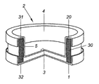
- the sole figure of the drawing shows a perspective view through a saucer according to the invention, wherein a part of the saucer has been cut away.
- the saucer according to the invention consists of a bottom part 1, which has the shape of a Circular disk of metal has, whereby on the outer periphery an edge a few millimeters after protrudes above.
- the bottom part 1 could also be provided with an internal opening, for example in the form of a circular hole.
- a resilient ring 30 for example made of rubber.
- the lower annular surface 32 of the resilient member 30 is located on the bottom part 1, while on the upper annular surface 31 of the part 30th a substantially cup-shaped centering body 2 rests.
- the centering body has an in Substantially cylindrical inner edge part 5, which in a bottom or support part. 3 ends.
- the annular outer boundary of the centering body 2 with formed a downward edge. In this way is the resilient part 30 at its annular surfaces 31 and 32 upwards and set down below.
- the foot of a piece of furniture or a wing is placed in an interior or trough 4 of the Centering 2 used so that the foot rests on the lower surface 3.
- the elastic member 30 becomes deform, so that the support surface 3 moves for the furniture foot down. at However, proper sizing remains a distance of a few millimeters to the bottom part. 1
- the compression spring part 30 is shown as a cylinder ring. It lies in the context of the present invention to use a flat piece of rubber and this to merge in a circle such that the annular one shown in the figure Design arises.
- the invention may be essential that between the edges of the centering or pot 2 and the bottom part 1 inwardly toward the resilient member 30th small tolerances are met, so that, for example, with shocks or Vibrations of the elastic part 30 remains almost firmly clamped and none critical deformations can occur
- the resilient member 30 could be biased to access this Way to prevent resonant vibrations in use of the coaster (Rocking) arise.
- the bottom part - with or without breakthrough - can be down with one Be equipped surface that good sliding properties can be ensured on the usual floors.
Landscapes
- Physics & Mathematics (AREA)
- Engineering & Computer Science (AREA)
- Acoustics & Sound (AREA)
- Multimedia (AREA)
- Table Equipment (AREA)
Abstract
Description
Claims (5)
- Untersetzer für Möbelfüße mit hoher Punktlast (Klavieruntersetzer), aufweisend einen Bodenteil (1), einen Zentrierkörper (2) mit einem Auflagerteil (3), wobei der Zentrierkörper (2) eine Mulde (4) aufweist, die nach außen hin durch einen Rand (5) des Zentrierkörpers (2) begrenzt ist, dadurch gekennzeichnet, dass der Zentrierkörper (2) topfförmig mit einem oberen, horizontal ausgerichteten ringförmigen Rand (20) ausgebildet ist; der Rand (20) oben auf der Oberfläche (31) eines federelastischen Ringes (30) aufliegt, der Boden des topfförmigen Zentrierkörpers (2) in den Innenraum des Ringes (30) bis nahe an den Auflageteil (3) hineinragt und dass der Ring (30) mit seiner unteren Ringfläche auf dem Bodenteil (3) aufruht.
- Untersetzer nach Anspruch 1, dadurch gekennzeichnet, dass der Ring (30) aus einem gummielastischen Material gebildet ist und im Wesentlichen ringzylindrisch ausgebildet ist.
- Untersetzer nach Anspruch 1, dadurch gekennzeichnet, dass der Ring (30) als Spiralfeder ausgebildet ist.
- Untersetzer nach mindestens einem der Ansprüche 1 bis 3, dadurch gekennzeichnet, dass der obere Rand (20) des Zentrierkörpers (2) mit einem nach unten gerichteten äußeren Rand ausgebildet ist.
- Untersetzer nach mindestens einem der Ansprüche 1 bis 4, dadurch gekennzeichnet, dass der Bodenteil (1) mit einem nach oben gerichteten äußeren Rand ausgebildet ist.
Applications Claiming Priority (2)
| Application Number | Priority Date | Filing Date | Title |
|---|---|---|---|
| DE20214062U DE20214062U1 (de) | 2002-09-11 | 2002-09-11 | Untersetzer für Möbelfüße |
| DE20214062U | 2002-09-11 |
Publications (2)
| Publication Number | Publication Date |
|---|---|
| EP1397980A1 true EP1397980A1 (de) | 2004-03-17 |
| EP1397980B1 EP1397980B1 (de) | 2005-10-12 |
Family
ID=31724925
Family Applications (1)
| Application Number | Title | Priority Date | Filing Date |
|---|---|---|---|
| EP03019730A Expired - Lifetime EP1397980B1 (de) | 2002-09-11 | 2003-08-29 | Untersetzer für Möbelfüsse |
Country Status (3)
| Country | Link |
|---|---|
| EP (1) | EP1397980B1 (de) |
| AT (1) | ATE306205T1 (de) |
| DE (2) | DE20214062U1 (de) |
Citations (4)
| Publication number | Priority date | Publication date | Assignee | Title |
|---|---|---|---|---|
| US1612460A (en) * | 1925-02-12 | 1926-12-28 | Robert Alt & Co | Resilient support or base for chairs, fauteuils, benches, typewriting machines, and the like |
| FR1313753A (fr) * | 1961-07-05 | 1963-01-04 | Patins amortisseurs de pieds de meubles | |
| DE4031558A1 (de) * | 1990-10-05 | 1992-04-09 | Freudenberg Carl Fa | Vorgespanntes elastisches lager mit kompressiblem federkoerper |
| DE29513067U1 (de) | 1995-08-02 | 1995-10-19 | Przybilla, Bernhard, 10437 Berlin | Untersetzer für Möbelfüße |
-
2002
- 2002-09-11 DE DE20214062U patent/DE20214062U1/de not_active Expired - Lifetime
-
2003
- 2003-08-29 EP EP03019730A patent/EP1397980B1/de not_active Expired - Lifetime
- 2003-08-29 AT AT03019730T patent/ATE306205T1/de not_active IP Right Cessation
- 2003-08-29 DE DE50301342T patent/DE50301342D1/de not_active Expired - Lifetime
Patent Citations (4)
| Publication number | Priority date | Publication date | Assignee | Title |
|---|---|---|---|---|
| US1612460A (en) * | 1925-02-12 | 1926-12-28 | Robert Alt & Co | Resilient support or base for chairs, fauteuils, benches, typewriting machines, and the like |
| FR1313753A (fr) * | 1961-07-05 | 1963-01-04 | Patins amortisseurs de pieds de meubles | |
| DE4031558A1 (de) * | 1990-10-05 | 1992-04-09 | Freudenberg Carl Fa | Vorgespanntes elastisches lager mit kompressiblem federkoerper |
| DE29513067U1 (de) | 1995-08-02 | 1995-10-19 | Przybilla, Bernhard, 10437 Berlin | Untersetzer für Möbelfüße |
Also Published As
| Publication number | Publication date |
|---|---|
| DE20214062U1 (de) | 2004-02-12 |
| ATE306205T1 (de) | 2005-10-15 |
| DE50301342D1 (de) | 2006-02-23 |
| EP1397980B1 (de) | 2005-10-12 |
Similar Documents
| Publication | Publication Date | Title |
|---|---|---|
| DE60205325T2 (de) | Hydraulisches, schwingungsdämpfendes Lager mit einem verrasteten Entkopplungsventil | |
| DE2953729A1 (en) | Mount to absorb shocks | |
| DE20019569U1 (de) | Sitzvorrichtung für ein Sitzmöbel | |
| DE19511642C2 (de) | Oberes Federbeinstützlager für Radaufhängungen in einem Kraftfahrzeug | |
| EP3286042A1 (de) | Lenkradeinheit, gassackmodul und lenkradkörper | |
| EP3017738A1 (de) | Standfuss eines gerätes, insbesondere einer tisch-küchenmaschine | |
| EP1590579B1 (de) | Lagerkonstruktion zur gedämpften übertragung von stoss- und/oder schwingungskräften | |
| DE1087409B (de) | Vibrationsisolator | |
| DE1285261B (de) | Schwingungsdaempfendes Maschinenlager | |
| EP1397980B1 (de) | Untersetzer für Möbelfüsse | |
| DE102008015129B3 (de) | Unterputz-Schalter mit mindestens einer innerhalb eines Abdeckrahmens angeordneten Betätigungswippe | |
| DE102007063037A1 (de) | Zusatzmatte für ein Fahrzeug | |
| DE19831114C2 (de) | Elastisches Pendellager, insbesondere zur Aufhängung einer Abgasanlage an einem Fahrzeugboden | |
| EP2659810B1 (de) | Standfuß eines Gerätes, insbesondere einer Tisch-Küchenmaschine | |
| DE19626248C1 (de) | Überlastsicherung für die Waagschale einer oberschaligen Waage | |
| DE102006026822B4 (de) | Schwingungsdämpfer für ein Fahrzeug | |
| DE19711039C1 (de) | Stützfuß | |
| DE10064881A1 (de) | Fusslager für höhenverstellbare Füsse eines Traggestells für Bade- und Brausewannen | |
| DE102008008919A1 (de) | Dentalgerät | |
| EP2870903B1 (de) | Standfuß einer Tisch-Küchenmaschine | |
| DE1654631C3 (de) | Tischbein mit einem am Tischbein angeordneten Standfuß | |
| EP0828906B1 (de) | Kunststoff-lichtschacht mit abdeckung | |
| DE3218947A1 (de) | Hydraulisch gedaempftes elastisches lager | |
| DE7618116U1 (de) | Anschlagdaempfer fuer tueren, insbesondere fuer tueren von kuechenmoebeln | |
| DE60011740T2 (de) | Matratzenstütze mit elastischen Bällen |
Legal Events
| Date | Code | Title | Description |
|---|---|---|---|
| PUAI | Public reference made under article 153(3) epc to a published international application that has entered the european phase |
Free format text: ORIGINAL CODE: 0009012 |
|
| AK | Designated contracting states |
Kind code of ref document: A1 Designated state(s): AT BE BG CH CY CZ DE DK EE ES FI FR GB GR HU IE IT LI LU MC NL PT RO SE SI SK TR |
|
| AX | Request for extension of the european patent |
Extension state: AL LT LV MK |
|
| 17P | Request for examination filed |
Effective date: 20040402 |
|
| 17Q | First examination report despatched |
Effective date: 20040618 |
|
| AKX | Designation fees paid |
Designated state(s): AT BE BG CH CY CZ DE DK EE ES FI FR GB GR HU IE IT LI LU MC NL PT RO SE SI SK TR |
|
| RAP1 | Party data changed (applicant data changed or rights of an application transferred) |
Owner name: RIECKEN, JAN-CHRISTOPH |
|
| GRAP | Despatch of communication of intention to grant a patent |
Free format text: ORIGINAL CODE: EPIDOSNIGR1 |
|
| GRAS | Grant fee paid |
Free format text: ORIGINAL CODE: EPIDOSNIGR3 |
|
| GRAA | (expected) grant |
Free format text: ORIGINAL CODE: 0009210 |
|
| AK | Designated contracting states |
Kind code of ref document: B1 Designated state(s): AT BE BG CH CY CZ DE DK EE ES FI FR GB GR HU IE IT LI LU MC NL PT RO SE SI SK TR |
|
| PG25 | Lapsed in a contracting state [announced via postgrant information from national office to epo] |
Ref country code: CZ Free format text: LAPSE BECAUSE OF FAILURE TO SUBMIT A TRANSLATION OF THE DESCRIPTION OR TO PAY THE FEE WITHIN THE PRESCRIBED TIME-LIMIT Effective date: 20051012 Ref country code: SI Free format text: LAPSE BECAUSE OF FAILURE TO SUBMIT A TRANSLATION OF THE DESCRIPTION OR TO PAY THE FEE WITHIN THE PRESCRIBED TIME-LIMIT Effective date: 20051012 Ref country code: RO Free format text: LAPSE BECAUSE OF FAILURE TO SUBMIT A TRANSLATION OF THE DESCRIPTION OR TO PAY THE FEE WITHIN THE PRESCRIBED TIME-LIMIT Effective date: 20051012 Ref country code: NL Free format text: LAPSE BECAUSE OF FAILURE TO SUBMIT A TRANSLATION OF THE DESCRIPTION OR TO PAY THE FEE WITHIN THE PRESCRIBED TIME-LIMIT Effective date: 20051012 Ref country code: IE Free format text: LAPSE BECAUSE OF FAILURE TO SUBMIT A TRANSLATION OF THE DESCRIPTION OR TO PAY THE FEE WITHIN THE PRESCRIBED TIME-LIMIT Effective date: 20051012 Ref country code: SK Free format text: LAPSE BECAUSE OF FAILURE TO SUBMIT A TRANSLATION OF THE DESCRIPTION OR TO PAY THE FEE WITHIN THE PRESCRIBED TIME-LIMIT Effective date: 20051012 Ref country code: IT Free format text: LAPSE BECAUSE OF FAILURE TO SUBMIT A TRANSLATION OF THE DESCRIPTION OR TO PAY THE FEE WITHIN THE PRESCRIBED TIME-LIMIT;WARNING: LAPSES OF ITALIAN PATENTS WITH EFFECTIVE DATE BEFORE 2007 MAY HAVE OCCURRED AT ANY TIME BEFORE 2007. THE CORRECT EFFECTIVE DATE MAY BE DIFFERENT FROM THE ONE RECORDED. Effective date: 20051012 Ref country code: FI Free format text: LAPSE BECAUSE OF FAILURE TO SUBMIT A TRANSLATION OF THE DESCRIPTION OR TO PAY THE FEE WITHIN THE PRESCRIBED TIME-LIMIT Effective date: 20051012 |
|
| REG | Reference to a national code |
Ref country code: GB Ref legal event code: FG4D Free format text: NOT ENGLISH |
|
| REG | Reference to a national code |
Ref country code: CH Ref legal event code: EP |
|
| REG | Reference to a national code |
Ref country code: IE Ref legal event code: FG4D Free format text: LANGUAGE OF EP DOCUMENT: GERMAN |
|
| PG25 | Lapsed in a contracting state [announced via postgrant information from national office to epo] |
Ref country code: SE Free format text: LAPSE BECAUSE OF FAILURE TO SUBMIT A TRANSLATION OF THE DESCRIPTION OR TO PAY THE FEE WITHIN THE PRESCRIBED TIME-LIMIT Effective date: 20060112 Ref country code: GR Free format text: LAPSE BECAUSE OF FAILURE TO SUBMIT A TRANSLATION OF THE DESCRIPTION OR TO PAY THE FEE WITHIN THE PRESCRIBED TIME-LIMIT Effective date: 20060112 Ref country code: DK Free format text: LAPSE BECAUSE OF FAILURE TO SUBMIT A TRANSLATION OF THE DESCRIPTION OR TO PAY THE FEE WITHIN THE PRESCRIBED TIME-LIMIT Effective date: 20060112 Ref country code: BG Free format text: LAPSE BECAUSE OF FAILURE TO SUBMIT A TRANSLATION OF THE DESCRIPTION OR TO PAY THE FEE WITHIN THE PRESCRIBED TIME-LIMIT Effective date: 20060112 |
|
| PG25 | Lapsed in a contracting state [announced via postgrant information from national office to epo] |
Ref country code: ES Free format text: LAPSE BECAUSE OF FAILURE TO SUBMIT A TRANSLATION OF THE DESCRIPTION OR TO PAY THE FEE WITHIN THE PRESCRIBED TIME-LIMIT Effective date: 20060123 |
|
| REG | Reference to a national code |
Ref country code: CH Ref legal event code: NV Representative=s name: KIRKER & CIE SA |
|
| GBT | Gb: translation of ep patent filed (gb section 77(6)(a)/1977) |
Effective date: 20060120 |
|
| REF | Corresponds to: |
Ref document number: 50301342 Country of ref document: DE Date of ref document: 20060223 Kind code of ref document: P |
|
| PG25 | Lapsed in a contracting state [announced via postgrant information from national office to epo] |
Ref country code: PT Free format text: LAPSE BECAUSE OF FAILURE TO SUBMIT A TRANSLATION OF THE DESCRIPTION OR TO PAY THE FEE WITHIN THE PRESCRIBED TIME-LIMIT Effective date: 20060313 |
|
| NLV1 | Nl: lapsed or annulled due to failure to fulfill the requirements of art. 29p and 29m of the patents act | ||
| PG25 | Lapsed in a contracting state [announced via postgrant information from national office to epo] |
Ref country code: HU Free format text: LAPSE BECAUSE OF FAILURE TO SUBMIT A TRANSLATION OF THE DESCRIPTION OR TO PAY THE FEE WITHIN THE PRESCRIBED TIME-LIMIT Effective date: 20060413 |
|
| REG | Reference to a national code |
Ref country code: IE Ref legal event code: FD4D |
|
| PLBE | No opposition filed within time limit |
Free format text: ORIGINAL CODE: 0009261 |
|
| STAA | Information on the status of an ep patent application or granted ep patent |
Free format text: STATUS: NO OPPOSITION FILED WITHIN TIME LIMIT |
|
| PG25 | Lapsed in a contracting state [announced via postgrant information from national office to epo] |
Ref country code: BE Free format text: LAPSE BECAUSE OF NON-PAYMENT OF DUE FEES Effective date: 20060831 Ref country code: MC Free format text: LAPSE BECAUSE OF NON-PAYMENT OF DUE FEES Effective date: 20060831 |
|
| 26N | No opposition filed |
Effective date: 20060713 |
|
| PG25 | Lapsed in a contracting state [announced via postgrant information from national office to epo] |
Ref country code: FR Free format text: LAPSE BECAUSE OF FAILURE TO SUBMIT A TRANSLATION OF THE DESCRIPTION OR TO PAY THE FEE WITHIN THE PRESCRIBED TIME-LIMIT Effective date: 20061020 |
|
| EN | Fr: translation not filed | ||
| PG25 | Lapsed in a contracting state [announced via postgrant information from national office to epo] |
Ref country code: AT Free format text: LAPSE BECAUSE OF NON-PAYMENT OF DUE FEES Effective date: 20060829 |
|
| BERE | Be: lapsed |
Owner name: RIECKEN, JAN-CHRISTOPH Effective date: 20060831 |
|
| PG25 | Lapsed in a contracting state [announced via postgrant information from national office to epo] |
Ref country code: EE Free format text: LAPSE BECAUSE OF FAILURE TO SUBMIT A TRANSLATION OF THE DESCRIPTION OR TO PAY THE FEE WITHIN THE PRESCRIBED TIME-LIMIT Effective date: 20051012 |
|
| PG25 | Lapsed in a contracting state [announced via postgrant information from national office to epo] |
Ref country code: TR Free format text: LAPSE BECAUSE OF FAILURE TO SUBMIT A TRANSLATION OF THE DESCRIPTION OR TO PAY THE FEE WITHIN THE PRESCRIBED TIME-LIMIT Effective date: 20051012 Ref country code: LU Free format text: LAPSE BECAUSE OF NON-PAYMENT OF DUE FEES Effective date: 20060829 |
|
| PG25 | Lapsed in a contracting state [announced via postgrant information from national office to epo] |
Ref country code: CY Free format text: LAPSE BECAUSE OF FAILURE TO SUBMIT A TRANSLATION OF THE DESCRIPTION OR TO PAY THE FEE WITHIN THE PRESCRIBED TIME-LIMIT Effective date: 20051012 Ref country code: FR Free format text: LAPSE BECAUSE OF FAILURE TO SUBMIT A TRANSLATION OF THE DESCRIPTION OR TO PAY THE FEE WITHIN THE PRESCRIBED TIME-LIMIT Effective date: 20051012 |
|
| PGFP | Annual fee paid to national office [announced via postgrant information from national office to epo] |
Ref country code: GB Payment date: 20200917 Year of fee payment: 18 |
|
| PGFP | Annual fee paid to national office [announced via postgrant information from national office to epo] |
Ref country code: CH Payment date: 20200925 Year of fee payment: 18 |
|
| PGFP | Annual fee paid to national office [announced via postgrant information from national office to epo] |
Ref country code: DE Payment date: 20210902 Year of fee payment: 19 |
|
| REG | Reference to a national code |
Ref country code: CH Ref legal event code: PL |
|
| GBPC | Gb: european patent ceased through non-payment of renewal fee |
Effective date: 20210829 |
|
| PG25 | Lapsed in a contracting state [announced via postgrant information from national office to epo] |
Ref country code: LI Free format text: LAPSE BECAUSE OF NON-PAYMENT OF DUE FEES Effective date: 20210831 Ref country code: CH Free format text: LAPSE BECAUSE OF NON-PAYMENT OF DUE FEES Effective date: 20210831 |
|
| PG25 | Lapsed in a contracting state [announced via postgrant information from national office to epo] |
Ref country code: GB Free format text: LAPSE BECAUSE OF NON-PAYMENT OF DUE FEES Effective date: 20210829 |
|
| REG | Reference to a national code |
Ref country code: DE Ref legal event code: R119 Ref document number: 50301342 Country of ref document: DE |
|
| PG25 | Lapsed in a contracting state [announced via postgrant information from national office to epo] |
Ref country code: DE Free format text: LAPSE BECAUSE OF NON-PAYMENT OF DUE FEES Effective date: 20230301 |