EP1398094A1 - Procédé et dispositif pour déterminer la longueur de branche de pièces cintrées - Google Patents
Procédé et dispositif pour déterminer la longueur de branche de pièces cintrées Download PDFInfo
- Publication number
- EP1398094A1 EP1398094A1 EP02020284A EP02020284A EP1398094A1 EP 1398094 A1 EP1398094 A1 EP 1398094A1 EP 02020284 A EP02020284 A EP 02020284A EP 02020284 A EP02020284 A EP 02020284A EP 1398094 A1 EP1398094 A1 EP 1398094A1
- Authority
- EP
- European Patent Office
- Prior art keywords
- bending
- bending angle
- leg
- determining
- leg end
- Prior art date
- Legal status (The legal status is an assumption and is not a legal conclusion. Google has not performed a legal analysis and makes no representation as to the accuracy of the status listed.)
- Granted
Links
Images



Classifications
-
- B—PERFORMING OPERATIONS; TRANSPORTING
- B21—MECHANICAL METAL-WORKING WITHOUT ESSENTIALLY REMOVING MATERIAL; PUNCHING METAL
- B21D—WORKING OR PROCESSING OF SHEET METAL OR METAL TUBES, RODS OR PROFILES WITHOUT ESSENTIALLY REMOVING MATERIAL; PUNCHING METAL
- B21D5/00—Bending sheet metal along straight lines, e.g. to form simple curves
- B21D5/002—Positioning devices
-
- B—PERFORMING OPERATIONS; TRANSPORTING
- B21—MECHANICAL METAL-WORKING WITHOUT ESSENTIALLY REMOVING MATERIAL; PUNCHING METAL
- B21D—WORKING OR PROCESSING OF SHEET METAL OR METAL TUBES, RODS OR PROFILES WITHOUT ESSENTIALLY REMOVING MATERIAL; PUNCHING METAL
- B21D5/00—Bending sheet metal along straight lines, e.g. to form simple curves
- B21D5/02—Bending sheet metal along straight lines, e.g. to form simple curves on press brakes without making use of clamping means
- B21D5/0209—Tools therefor
-
- G—PHYSICS
- G01—MEASURING; TESTING
- G01B—MEASURING LENGTH, THICKNESS OR SIMILAR LINEAR DIMENSIONS; MEASURING ANGLES; MEASURING AREAS; MEASURING IRREGULARITIES OF SURFACES OR CONTOURS
- G01B21/00—Measuring arrangements or details thereof, where the measuring technique is not covered by the other groups of this subclass, unspecified or not relevant
- G01B21/02—Measuring arrangements or details thereof, where the measuring technique is not covered by the other groups of this subclass, unspecified or not relevant for measuring length, width, or thickness
-
- G—PHYSICS
- G01—MEASURING; TESTING
- G01B—MEASURING LENGTH, THICKNESS OR SIMILAR LINEAR DIMENSIONS; MEASURING ANGLES; MEASURING AREAS; MEASURING IRREGULARITIES OF SURFACES OR CONTOURS
- G01B21/00—Measuring arrangements or details thereof, where the measuring technique is not covered by the other groups of this subclass, unspecified or not relevant
- G01B21/22—Measuring arrangements or details thereof, where the measuring technique is not covered by the other groups of this subclass, unspecified or not relevant for measuring angles or tapers; for testing the alignment of axes
Definitions
- the invention relates to a method and a device for Determination of the leg length of at least one of two means a bending tool bent at a bending angle against each other Leg on a bent part, wherein a bending angle vertex at the intersection of rectilinear and the bending angle enclosing Course of the legs of the bent part lies and a leg end of the leg in question this bounded by the bending angle vertex side.
- the invention further relates to a method and a device for bending workpieces, in the case of those of the above Method and of the above device for determination the leg length made use of a bent part becomes.
- the leg length forms the most important Functional dimension of a bent part.
- a bending machine Bending part manually after its removal from the bending machine determine.
- the accuracy of the leg length determination is This is particularly affected by the fact that the not to be measured leg of the bent part at the bend line ideally in a straight line but rather with one another Radius merge into each other.
- the bending angle vertex as one the end points of a bent part leg and as an intersection of rectilinear courses of both bending part legs is therefore not real existent. Consequently, the bending angle peak in the Determining a leg length of a bent part, for example not directly touched.
- Special and only under Use of elaborate measurement technology to overcome difficulties occur in the case of open bending angles, i. of bending angles over 90 °, up.
- the leg length is in the interest of a possible exact determination not immediately but about the location of the Bending angle peak and the position of the leg end determined.
- the position of the bending angle vertex the position of the in the practice of usually not really existing intersection the rectilinear courses of the abutting bending part legs considered.
- the bending part to be measured for defined arrangement held in the bending tool Based device This method feature is implemented by the Holding device according to claim 9.
- the bending device according to the invention serves as a holding device for the defined arrangement of the bent part in the Bending tool, the bending tool itself (claim 19).
- the determination of the position of the bending angle vertex takes place in Advantageous embodiment of the invention with determination of the Bending angle (claims 3, 10).
- the Bending angle can be measured.
- the Bending angle but also after a so-called, in a device control to be deposited "bending formula".
- the bending formula describes the bending angle as a function of workpiece and tool related parameters.
- the bending part to be measured on a system and the Position of the bending angle vertex based on the position of the support of the bent part determined at the plant.
- the bending angle also provides the location of the support of the bent part at the plant with the required accuracy and to be provided with conventional means basis for the Determining the position of the bending angle vertex.
- the device according to the invention according to claim 11 one associated with the evaluation device Computer unit and a system for the bent part provided at which the bending part in the determination of the position of the bending angle vertex is supported.
- the computer unit serves based on the location of the support of the bent part of the plant the Determine the position of the bending angle vertex.
- the bending device according to the invention is used according to Claim 20, the bending tool as an attachment to the support of the bending part in determining the position of the bending angle vertex.
- the bending angle and / or the position of the leg end preferably non-contact, in particular optically determined.
- Alternative or supplementary But also tactile methods or systems can be used come.
- Embodiment of the device according to the invention for leg length determination as a detection unit for detection the position of the leg end provided a sensing device, which can be applied to the leg end. According to claim 15, this sensing device with the leg end at the Movement to be movable during the bending process.
- a positioning stop for the bending workpiece can be used (claim 16).
- the bending device according to the invention according to claim 21 as a sensing device of the detection unit for Detecting the position of the leg end a positioning stop the bending device provided on which the workpiece in front the machining for positioning relative to the bending tool can be applied.
- claim 23 is the positioning stop in development of the bending device according to the invention controlled movable.
- Figure 1 has a bending machine 1 for sheet metal processing a machine frame 2, on which a press bar 3 handle lowered is guided. To drive the press bar 3 is used a hydraulic pressing beam drive 4.
- Dem Upper tool 5 is associated with a lower tool 7, which on a Machine table 8 is mounted.
- a suggestively detectable tactile bending angle sensor 9 is integrated in the upper tool 5 of the Gesenkbiegewerkmaschinemaschinemaschines 6.
- the bending angle sensor 9 corresponds in construction and Operation of the device described in EP 0 775 028 B1.
- a backgauge system 10 accommodated on the side facing away from the operator side of the bending machine 1
- Opposite is a machine control provided in the form of a CNC controller 11.
- this includes Backgauge system 10 two backstops 15, 16.
- the stop fingers 17, 18 form positioning stops for the plane to be folded Sheet metal blank and are independent of each other in the three directions of space movable.
- the motion control the stop finger 17, 18 takes place by means of the CNC controller 11.
- Below a workpiece system 19 is on the stop finger 17th a camera 20 attached. Accordingly, the stop finger 18 provided below a workpiece system 21 with a camera 22.
- the directions of the stop fingers 17, 18 executable Movements are illustrated in Figure 2 by arrows.
- the legs abut 13, 14 of the bending part 12 is not ideal straight course but rather with each other with a radius above.
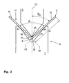
- a rectilinear course 29 of the leg 13 and a straight course 30 of the leg 14 intersect in a bending angle vertex S, which in the direction bisector 23 is below the bending part 12.
- a Thigh length b of the leg 13 extends between the Bending angle vertex S and one leg end E.
- the bending angle sensor 9 is part of a device 31 for determining the position of the bending angle vertex S.
- the bending angle sensor 9 is doing with a computer unit 32 which in turn has access to a memory 33, in which the course of the bisector 23 of the Gesenknut 24 on the lower tool 7 and the position of the support points A1, A2 on the flanks 27, 28 of the Gesenknut 24 as a function of the bending angle ß are deposited.
- the Flanks 27, 28 of the Gesenknut 24 a part of the device 31st for determining the position of the bending angle vertex S.
- bending angle ß determines the computer unit 32, the angle ß / 2, below which is the rectilinear course 29 of the leg 13 of the bending part 12 with respect to the bisector 23 of the Die groove 24 extends. From the angle ß / 2, the location of A1 as well the course of the bisectors 23 determines the computer unit Finally, the position of the bending angle vertex S as an intersection of a flank 27 of the Gesenknut 24 in A1 tangent and at the angle ß / 2 with respect to the bisector 23 straight lines with the bisector 23rd
- a likewise shown in Figure 4 device 34 for determination the position of the leg end E includes the backgauge 15 of the backgauge system 10 and the stop finger 17 back gauge 15 mounted camera 20. This forms a detection unit for detecting the position of Leg end E.
- the picture taken by the camera 20 of the Leg end E is in the form of signals from a computer unit 35 transmitted. Also connected to the computer unit 35 is the backgauge 15, in detail its motion control. After the camera 20 on the stop finger 17 a defined Position is about the position of the stop finger 17 determines the position of the camera 20. From the situation information obtained in this way and the signals from the camera 20 the computer unit 35 determines the position of the leg end E.
- stop finger 17 for holding the camera 20 is recommended in particular because of the fact that the Stop finger 17 at the time at which the location of the Leg end E is to determine, out of function and thus free is available.
- the stop finger 17 is used, in detail its workpiece system 19, only at the beginning of the bending process.
- Stop finger 17, 18 is the later course of the bending line defined at the bending part. During the bending process and then the initially flat sheet metal blank is from the stop fingers 17, 18 lifted.
- the bending angle ß also by means of in the CNC control 11 calculate the calculated bending formula.
- This bending formula describes the bending angle ß as a function of geometry of upper tool 6 and lower tool 7, the material strength, the thickness of the sheet to be deformed and the penetration depth of the upper tool 5 on the lower tool 7.
- the tactile Biegewinkel sensor 9 can be used to determine the bending angle ß instead of the tactile Biegewinkel sensor 9 also non-contact optical systems used become.
- at least one the cameras 20, 22 on the backgauge system 10 to use.
- the position of the leg end E can be tactile Determine facilities. For example, at least one the stop finger 17, 18 adjacent to the leg end E. follow this during the bending process.
- the Determining the leg length b also serve to create the Bending part 12 to deviations from its three-dimensional Check target shape. For example, with larger bending lengths the leg length b at several points along the bending line 26 are determined. Also conceivable is a review the angularity of the bending part 12. The determined measurement data can be automatically logged in any case. The Effects of corrections given by the correction unit 38 can be visualized on demand.
Landscapes
- Physics & Mathematics (AREA)
- General Physics & Mathematics (AREA)
- Engineering & Computer Science (AREA)
- Mechanical Engineering (AREA)
- Bending Of Plates, Rods, And Pipes (AREA)
- Cable Accessories (AREA)
- Length-Measuring Instruments Using Mechanical Means (AREA)
Priority Applications (4)
| Application Number | Priority Date | Filing Date | Title |
|---|---|---|---|
| EP02020284A EP1398094B1 (fr) | 2002-09-11 | 2002-09-11 | Procédé et dispositif pour déterminer la longueur de branche de pièces cintrées |
| AT02020284T ATE326297T1 (de) | 2002-09-11 | 2002-09-11 | Verfahren und vorrichtung zur bestimmung der schenkellänge an einem biegeteil |
| DE50206821T DE50206821D1 (de) | 2002-09-11 | 2002-09-11 | Verfahren und Vorrichtung zur Bestimmung der Schenkellänge an einem Biegeteil |
| US10/660,042 US6922903B2 (en) | 2002-09-11 | 2003-09-11 | Method and apparatus for measuring bent workpieces |
Applications Claiming Priority (1)
| Application Number | Priority Date | Filing Date | Title |
|---|---|---|---|
| EP02020284A EP1398094B1 (fr) | 2002-09-11 | 2002-09-11 | Procédé et dispositif pour déterminer la longueur de branche de pièces cintrées |
Publications (2)
| Publication Number | Publication Date |
|---|---|
| EP1398094A1 true EP1398094A1 (fr) | 2004-03-17 |
| EP1398094B1 EP1398094B1 (fr) | 2006-05-17 |
Family
ID=31725385
Family Applications (1)
| Application Number | Title | Priority Date | Filing Date |
|---|---|---|---|
| EP02020284A Expired - Lifetime EP1398094B1 (fr) | 2002-09-11 | 2002-09-11 | Procédé et dispositif pour déterminer la longueur de branche de pièces cintrées |
Country Status (4)
| Country | Link |
|---|---|
| US (1) | US6922903B2 (fr) |
| EP (1) | EP1398094B1 (fr) |
| AT (1) | ATE326297T1 (fr) |
| DE (1) | DE50206821D1 (fr) |
Cited By (6)
| Publication number | Priority date | Publication date | Assignee | Title |
|---|---|---|---|---|
| AT511107A4 (de) * | 2011-05-09 | 2012-09-15 | Trumpf Maschinen Austria Gmbh | Biegepresse mit anschlagvorrichtung und verfahren zum betrieb einer biegepresse mit anschlagvorrichtung |
| EP1961502A3 (fr) * | 2007-02-23 | 2013-09-11 | Bystronic Laser AG | Procédé et dispositif destinés au pliage de pièces |
| AT514077B1 (de) * | 2013-06-20 | 2014-10-15 | Trumpf Maschinen Austria Gmbh | Hinteranschlagvorrichtung für eine Biegemaschine |
| AT520563B1 (de) * | 2017-12-22 | 2019-05-15 | Trumpf Maschinen Austria Gmbh & Co Kg | Bestimmung der Biegeverkürzung eines zu biegenden Blechwerkstückes |
| CN111530988A (zh) * | 2020-05-16 | 2020-08-14 | 合肥浩凌机械设计制造有限公司 | 一种金属板材冲压成型工艺 |
| CN114786833A (zh) * | 2019-12-19 | 2022-07-22 | 特鲁普机械奥地利有限公司及两合公司 | 折弯机和控制装置 |
Families Citing this family (10)
| Publication number | Priority date | Publication date | Assignee | Title |
|---|---|---|---|---|
| US7415400B2 (en) * | 2002-10-15 | 2008-08-19 | Livermore Software Technology Corporation | System, method, and device for designing a die to stamp metal parts to an exact final dimension |
| DE202007002793U1 (de) * | 2007-02-22 | 2007-05-10 | Eduard Wille Gmbh & Co. Kg | Winkelmesseinrichtung |
| US8601854B2 (en) * | 2011-02-14 | 2013-12-10 | Satoshi Sakai | Method of bending sheet metal |
| CN102699653B (zh) * | 2012-05-22 | 2016-04-20 | 大明重工有限公司 | 一种多厚度金属板材拼焊折弯方法 |
| EP3030359B1 (fr) * | 2013-08-09 | 2020-06-17 | Bystronic Laser AG | Presse à plier |
| EP2982933B1 (fr) * | 2014-08-07 | 2021-03-24 | SALVAGNINI ITALIA S.p.A. | Dispositif et procédé pour mesurer l'angle de pliage d'un objet |
| DE102014225169A1 (de) * | 2014-12-08 | 2016-06-09 | Robert Bosch Gmbh | Pneumatischer Messdorn und Messsystem |
| AT516260B1 (de) * | 2014-12-17 | 2016-04-15 | Trumpf Maschinen Austria Gmbh | Biegewerkzeug mit einer Längsversatz-Messvorrichtung |
| US11027323B2 (en) | 2016-06-10 | 2021-06-08 | Advanced Orthodontic Solutions | Method and apparatus for auto-calibration of a wire bending machine |
| CN113267112B (zh) * | 2021-03-29 | 2022-08-19 | 河北沧海核装备科技股份有限公司 | 一种感应加热弯管弯曲角度测量方法 |
Citations (4)
| Publication number | Priority date | Publication date | Assignee | Title |
|---|---|---|---|---|
| US4660293A (en) * | 1985-10-10 | 1987-04-28 | George Kovacs | Measuring instrument for angled material |
| US5842366A (en) * | 1995-06-12 | 1998-12-01 | Trumpf Gmbh & Company | Method and a tooling machine for bending workpieces |
| US6289598B1 (en) * | 1998-08-12 | 2001-09-18 | Tanabe Seisa Sho Limited | Length measuring device |
| US20010049953A1 (en) * | 1996-12-20 | 2001-12-13 | Amada Company Ltd. | Apparatus for preparing data for manufacturing products with a pre-determined shape, having a memory storing a bending order information |
Family Cites Families (20)
| Publication number | Priority date | Publication date | Assignee | Title |
|---|---|---|---|---|
| IT997137B (it) * | 1973-09-04 | 1975-12-30 | Finike Italiana Marposs | Apparecchiatura per misurare la lunghezza di segmenti curvilinei |
| US5046852A (en) * | 1988-09-16 | 1991-09-10 | The Boeing Company | Method and apparatus for bending an elongate workpiece |
| SE505985C2 (sv) * | 1989-11-14 | 1997-10-27 | Amada Co Ltd | Sätt och anordning för avkänning av bockningsvinklar för en metallplåt under bockningen |
| WO1991013318A1 (fr) * | 1990-02-23 | 1991-09-05 | Amada Company, Limited | Procede et appareil de mesure d'angles de façonnage |
| US5531087A (en) * | 1990-10-05 | 1996-07-02 | Kabushiki Kaisha Komatsu Seisakusho | Metal sheet bending machine |
| CH689613A5 (fr) * | 1992-10-20 | 1999-07-15 | Beyeler Machines Sa | Dispositif de mesure de l'angle de pliage d'une tôle dans une presse. |
| JP2630720B2 (ja) * | 1992-11-06 | 1997-07-16 | 丸機械工業株式会社 | 板材の折曲げ角検出装置及びこれを使用したプレス機械の運転方法 |
| DE4312565C2 (de) | 1993-04-17 | 2001-12-13 | Trumpf Maschinen Austria Gmbh | Biegemaschine zum Biegen flächiger Werkstücke |
| WO1994027756A1 (fr) * | 1993-05-24 | 1994-12-08 | Kabushiki Kaisha Komatsu Seisakusho | Dispositif permettant de detecter un angle de pliage et systeme d'extraction de lignes droites utilisees a cet effet, et appareil pour le reglage de la position de detection d'un angle de pliage |
| JP2752898B2 (ja) * | 1993-06-16 | 1998-05-18 | 株式会社小松製作所 | V曲げ加工におけるスプリングバック角度計測装置 |
| EP0769336B1 (fr) * | 1994-07-08 | 2003-01-29 | Amada Company, Limited | Procede de cintrage a l'aide d'une machine a cintrer, et machine a cintrer utilisee dans ce procede |
| GB2327123B (en) * | 1996-02-13 | 2000-09-13 | Amada Metrecs Co | Angle detection method for bending machines, and angle detection apparatus and angle sensor thereof |
| US5799530A (en) * | 1996-12-20 | 1998-09-01 | Amada Company, Limited | Method of bending operations and bending system using the same |
| JP3222094B2 (ja) * | 1997-08-04 | 2001-10-22 | 株式会社アマダ | 曲げ加工の折り込み線生成方法及びその方法を用いた曲げ加工システム |
| US6035242A (en) * | 1997-07-07 | 2000-03-07 | Amada Metrecs Company, Limited | Bending simulation method |
| JPH11125514A (ja) * | 1997-10-22 | 1999-05-11 | Komatsu Ltd | 曲げ角度検出装置 |
| JP3891697B2 (ja) * | 1998-07-02 | 2007-03-14 | 株式会社小松製作所 | プレスブレーキの曲げ角度検出方法および曲げ角度検出装置 |
| ES2251150T3 (es) * | 1999-11-19 | 2006-04-16 | Lvd Company Nv | Metodo y dispositivo para medir un angulo de plegado de una chapa en una maquina plegadora. |
| US6644080B2 (en) | 2001-01-12 | 2003-11-11 | Finn-Power International, Inc. | Press brake worksheet positioning system |
| JP3801466B2 (ja) * | 2001-07-17 | 2006-07-26 | 株式会社東洋工機 | 曲げ加工方法および曲げ加工装置 |
-
2002
- 2002-09-11 EP EP02020284A patent/EP1398094B1/fr not_active Expired - Lifetime
- 2002-09-11 AT AT02020284T patent/ATE326297T1/de active
- 2002-09-11 DE DE50206821T patent/DE50206821D1/de not_active Expired - Lifetime
-
2003
- 2003-09-11 US US10/660,042 patent/US6922903B2/en not_active Expired - Lifetime
Patent Citations (4)
| Publication number | Priority date | Publication date | Assignee | Title |
|---|---|---|---|---|
| US4660293A (en) * | 1985-10-10 | 1987-04-28 | George Kovacs | Measuring instrument for angled material |
| US5842366A (en) * | 1995-06-12 | 1998-12-01 | Trumpf Gmbh & Company | Method and a tooling machine for bending workpieces |
| US20010049953A1 (en) * | 1996-12-20 | 2001-12-13 | Amada Company Ltd. | Apparatus for preparing data for manufacturing products with a pre-determined shape, having a memory storing a bending order information |
| US6289598B1 (en) * | 1998-08-12 | 2001-09-18 | Tanabe Seisa Sho Limited | Length measuring device |
Cited By (11)
| Publication number | Priority date | Publication date | Assignee | Title |
|---|---|---|---|---|
| EP1961502A3 (fr) * | 2007-02-23 | 2013-09-11 | Bystronic Laser AG | Procédé et dispositif destinés au pliage de pièces |
| AT511107A4 (de) * | 2011-05-09 | 2012-09-15 | Trumpf Maschinen Austria Gmbh | Biegepresse mit anschlagvorrichtung und verfahren zum betrieb einer biegepresse mit anschlagvorrichtung |
| AT511107B1 (de) * | 2011-05-09 | 2012-09-15 | Trumpf Maschinen Austria Gmbh | Biegepresse mit anschlagvorrichtung und verfahren zum betrieb einer biegepresse mit anschlagvorrichtung |
| AT514077B1 (de) * | 2013-06-20 | 2014-10-15 | Trumpf Maschinen Austria Gmbh | Hinteranschlagvorrichtung für eine Biegemaschine |
| AT514077A4 (de) * | 2013-06-20 | 2014-10-15 | Trumpf Maschinen Austria Gmbh | Hinteranschlagvorrichtung für eine Biegemaschine |
| US9592545B2 (en) | 2013-06-20 | 2017-03-14 | Trumpf Maschinen Austria Gmbh & Co. Kg. | Rear stop device for a bending machine |
| AT520563B1 (de) * | 2017-12-22 | 2019-05-15 | Trumpf Maschinen Austria Gmbh & Co Kg | Bestimmung der Biegeverkürzung eines zu biegenden Blechwerkstückes |
| AT520563A4 (de) * | 2017-12-22 | 2019-05-15 | Trumpf Maschinen Austria Gmbh & Co Kg | Bestimmung der Biegeverkürzung eines zu biegenden Blechwerkstückes |
| CN114786833A (zh) * | 2019-12-19 | 2022-07-22 | 特鲁普机械奥地利有限公司及两合公司 | 折弯机和控制装置 |
| CN114786833B (zh) * | 2019-12-19 | 2024-01-16 | 特鲁普机械奥地利有限公司及两合公司 | 折弯机和控制装置 |
| CN111530988A (zh) * | 2020-05-16 | 2020-08-14 | 合肥浩凌机械设计制造有限公司 | 一种金属板材冲压成型工艺 |
Also Published As
| Publication number | Publication date |
|---|---|
| US20040128846A1 (en) | 2004-07-08 |
| EP1398094B1 (fr) | 2006-05-17 |
| US6922903B2 (en) | 2005-08-02 |
| DE50206821D1 (de) | 2006-06-22 |
| ATE326297T1 (de) | 2006-06-15 |
Similar Documents
| Publication | Publication Date | Title |
|---|---|---|
| EP1398094B1 (fr) | Procédé et dispositif pour déterminer la longueur de branche de pièces cintrées | |
| DE102015105687B4 (de) | Roboter | |
| EP1931503B1 (fr) | Procede pour determiner un point central virtuel d'outil | |
| DE3731704C2 (de) | Verfahren und Anordnung zur Eichung eines an der Hand eines Industrieroboters montierten Sensors | |
| EP1961502B1 (fr) | Procédé et dispositif destinés au pliage de pièces | |
| EP2311583B1 (fr) | Procédé de détermination de l'épaisseur d'une pièce à usiner à l'aide d'une plieuse et une telle plieuse | |
| DE3902149A1 (de) | Blechbearbeitungsmaschine, insbesondere blechbiegemaschine mit einem blecheinspann-manipulator und einer blechpositionsdetektiereinrichtung | |
| EP2846943B1 (fr) | Procédé de manipulation automatisée d'un outil de cintrage et dispositif de fabrication | |
| EP1604789A2 (fr) | Méthode et dispositif pour améliorer la précision du positionnement d'un manipulateur | |
| DE1945017B2 (de) | Vorrichtung zum einstellen des arbeitspunktes eines in einem werkzeugtraeger befestigten werkzeuges | |
| DE69616865T2 (de) | Master-slave Steuerung für den Manipulator einer Abkantpresse | |
| EP1375083B1 (fr) | Procédé pour déterminer l'orientation relative de l'axe de déplacement d'un robot par rapport au système de coordonnées du robot | |
| EP1342514A2 (fr) | Dispositif pour detecter un angle de cintrage d'un anneau, et procédé de régulation d'une cintreuse | |
| DE2901376B2 (de) | Steuereinrichtung an Freibiegemaschinen | |
| EP0962843B1 (fr) | Procédé d'affichage non-linéaire de trajectoires d'outil d'une machine outil | |
| EP4076779B1 (fr) | Machine à cintrer pourvue d'un dispositif de commande | |
| DE10006512C2 (de) | Vorrichtung für eine Abkantpresse zum Messen des Biegewinkels am Werkstück | |
| DE4203284C2 (de) | Verfahren und Vorrichtung zum Programmieren numerisch gesteuerter Werkzeugmaschinen | |
| DE112017004487T5 (de) | Maschine und Verfahren zum Fluidstrahlschneiden | |
| DE102005051533B4 (de) | Verfahren zur Verbesserung der Positioniergenauigkeit eines Manipulators bezüglich eines Serienwerkstücks | |
| EP1635972B1 (fr) | Procede et dispositif pour travailler des pieces par formage | |
| DE112023006429T5 (de) | Steuervorrichtung, Parameterkorrekturverfahren und Programm | |
| DE10330915B4 (de) | Verfahren zur Kompensation von Verlagerungen | |
| EP4134182A1 (fr) | Procédé de profilage par rouleaux | |
| DE10242769C1 (de) | Verfahren zur Vermessung der Lage von robotergeführten Werkstücken und Messeinrichtung hierzu |
Legal Events
| Date | Code | Title | Description |
|---|---|---|---|
| PUAI | Public reference made under article 153(3) epc to a published international application that has entered the european phase |
Free format text: ORIGINAL CODE: 0009012 |
|
| AK | Designated contracting states |
Kind code of ref document: A1 Designated state(s): AT BE BG CH CY CZ DE DK EE ES FI FR GB GR IE IT LI LU MC NL PT SE SK TR |
|
| AX | Request for extension of the european patent |
Extension state: AL LT LV MK RO SI |
|
| 17P | Request for examination filed |
Effective date: 20040719 |
|
| 17Q | First examination report despatched |
Effective date: 20040907 |
|
| AKX | Designation fees paid |
Designated state(s): AT BE BG CH CY CZ DE DK EE ES FI FR GB GR IE IT LI LU MC NL PT SE SK TR |
|
| GRAP | Despatch of communication of intention to grant a patent |
Free format text: ORIGINAL CODE: EPIDOSNIGR1 |
|
| RIC1 | Information provided on ipc code assigned before grant |
Ipc: 7G 01B 21/22 B Ipc: 7G 01B 21/02 B Ipc: 7B 21D 5/00 A |
|
| GRAS | Grant fee paid |
Free format text: ORIGINAL CODE: EPIDOSNIGR3 |
|
| GRAA | (expected) grant |
Free format text: ORIGINAL CODE: 0009210 |
|
| AK | Designated contracting states |
Kind code of ref document: B1 Designated state(s): AT BE BG CH CY CZ DE DK EE ES FI FR GB GR IE IT LI LU MC NL PT SE SK TR |
|
| PG25 | Lapsed in a contracting state [announced via postgrant information from national office to epo] |
Ref country code: IE Free format text: LAPSE BECAUSE OF FAILURE TO SUBMIT A TRANSLATION OF THE DESCRIPTION OR TO PAY THE FEE WITHIN THE PRESCRIBED TIME-LIMIT Effective date: 20060517 Ref country code: CZ Free format text: LAPSE BECAUSE OF FAILURE TO SUBMIT A TRANSLATION OF THE DESCRIPTION OR TO PAY THE FEE WITHIN THE PRESCRIBED TIME-LIMIT Effective date: 20060517 Ref country code: SK Free format text: LAPSE BECAUSE OF FAILURE TO SUBMIT A TRANSLATION OF THE DESCRIPTION OR TO PAY THE FEE WITHIN THE PRESCRIBED TIME-LIMIT Effective date: 20060517 Ref country code: FI Free format text: LAPSE BECAUSE OF FAILURE TO SUBMIT A TRANSLATION OF THE DESCRIPTION OR TO PAY THE FEE WITHIN THE PRESCRIBED TIME-LIMIT Effective date: 20060517 |
|
| REG | Reference to a national code |
Ref country code: GB Ref legal event code: FG4D |
|
| REG | Reference to a national code |
Ref country code: CH Ref legal event code: EP |
|
| REG | Reference to a national code |
Ref country code: IE Ref legal event code: FG4D Free format text: LANGUAGE OF EP DOCUMENT: GERMAN Ref country code: GB Ref legal event code: ERR Free format text: NOTIFICATION HAS BEEN RECEIVED FROM THE EUROPEAN PATENT OFFICE THAT IT WAS PUBLISHED IN GERMAN |
|
| REF | Corresponds to: |
Ref document number: 50206821 Country of ref document: DE Date of ref document: 20060622 Kind code of ref document: P |
|
| PG25 | Lapsed in a contracting state [announced via postgrant information from national office to epo] |
Ref country code: SE Free format text: LAPSE BECAUSE OF FAILURE TO SUBMIT A TRANSLATION OF THE DESCRIPTION OR TO PAY THE FEE WITHIN THE PRESCRIBED TIME-LIMIT Effective date: 20060817 Ref country code: DK Free format text: LAPSE BECAUSE OF FAILURE TO SUBMIT A TRANSLATION OF THE DESCRIPTION OR TO PAY THE FEE WITHIN THE PRESCRIBED TIME-LIMIT Effective date: 20060817 |
|
| PG25 | Lapsed in a contracting state [announced via postgrant information from national office to epo] |
Ref country code: ES Free format text: LAPSE BECAUSE OF FAILURE TO SUBMIT A TRANSLATION OF THE DESCRIPTION OR TO PAY THE FEE WITHIN THE PRESCRIBED TIME-LIMIT Effective date: 20060828 |
|
| PG25 | Lapsed in a contracting state [announced via postgrant information from national office to epo] |
Ref country code: MC Free format text: LAPSE BECAUSE OF NON-PAYMENT OF DUE FEES Effective date: 20060930 |
|
| PG25 | Lapsed in a contracting state [announced via postgrant information from national office to epo] |
Ref country code: PT Free format text: LAPSE BECAUSE OF FAILURE TO SUBMIT A TRANSLATION OF THE DESCRIPTION OR TO PAY THE FEE WITHIN THE PRESCRIBED TIME-LIMIT Effective date: 20061017 |
|
| GBT | Gb: translation of ep patent filed (gb section 77(6)(a)/1977) |
Effective date: 20061002 |
|
| ET | Fr: translation filed | ||
| REG | Reference to a national code |
Ref country code: IE Ref legal event code: FD4D |
|
| PLBE | No opposition filed within time limit |
Free format text: ORIGINAL CODE: 0009261 |
|
| STAA | Information on the status of an ep patent application or granted ep patent |
Free format text: STATUS: NO OPPOSITION FILED WITHIN TIME LIMIT |
|
| 26N | No opposition filed |
Effective date: 20070220 |
|
| PG25 | Lapsed in a contracting state [announced via postgrant information from national office to epo] |
Ref country code: GR Free format text: LAPSE BECAUSE OF FAILURE TO SUBMIT A TRANSLATION OF THE DESCRIPTION OR TO PAY THE FEE WITHIN THE PRESCRIBED TIME-LIMIT Effective date: 20060818 |
|
| PG25 | Lapsed in a contracting state [announced via postgrant information from national office to epo] |
Ref country code: BG Free format text: LAPSE BECAUSE OF FAILURE TO SUBMIT A TRANSLATION OF THE DESCRIPTION OR TO PAY THE FEE WITHIN THE PRESCRIBED TIME-LIMIT Effective date: 20060817 Ref country code: EE Free format text: LAPSE BECAUSE OF FAILURE TO SUBMIT A TRANSLATION OF THE DESCRIPTION OR TO PAY THE FEE WITHIN THE PRESCRIBED TIME-LIMIT Effective date: 20060517 |
|
| PG25 | Lapsed in a contracting state [announced via postgrant information from national office to epo] |
Ref country code: TR Free format text: LAPSE BECAUSE OF FAILURE TO SUBMIT A TRANSLATION OF THE DESCRIPTION OR TO PAY THE FEE WITHIN THE PRESCRIBED TIME-LIMIT Effective date: 20060517 Ref country code: LU Free format text: LAPSE BECAUSE OF NON-PAYMENT OF DUE FEES Effective date: 20060911 |
|
| PG25 | Lapsed in a contracting state [announced via postgrant information from national office to epo] |
Ref country code: CY Free format text: LAPSE BECAUSE OF FAILURE TO SUBMIT A TRANSLATION OF THE DESCRIPTION OR TO PAY THE FEE WITHIN THE PRESCRIBED TIME-LIMIT Effective date: 20060517 |
|
| PGFP | Annual fee paid to national office [announced via postgrant information from national office to epo] |
Ref country code: GB Payment date: 20080915 Year of fee payment: 7 |
|
| PGFP | Annual fee paid to national office [announced via postgrant information from national office to epo] |
Ref country code: CH Payment date: 20081002 Year of fee payment: 7 |
|
| PGFP | Annual fee paid to national office [announced via postgrant information from national office to epo] |
Ref country code: FR Payment date: 20080926 Year of fee payment: 7 |
|
| REG | Reference to a national code |
Ref country code: CH Ref legal event code: PL |
|
| GBPC | Gb: european patent ceased through non-payment of renewal fee |
Effective date: 20090911 |
|
| REG | Reference to a national code |
Ref country code: FR Ref legal event code: ST Effective date: 20100531 |
|
| PG25 | Lapsed in a contracting state [announced via postgrant information from national office to epo] |
Ref country code: FR Free format text: LAPSE BECAUSE OF NON-PAYMENT OF DUE FEES Effective date: 20090930 |
|
| PG25 | Lapsed in a contracting state [announced via postgrant information from national office to epo] |
Ref country code: LI Free format text: LAPSE BECAUSE OF NON-PAYMENT OF DUE FEES Effective date: 20090930 Ref country code: CH Free format text: LAPSE BECAUSE OF NON-PAYMENT OF DUE FEES Effective date: 20090930 |
|
| PG25 | Lapsed in a contracting state [announced via postgrant information from national office to epo] |
Ref country code: GB Free format text: LAPSE BECAUSE OF NON-PAYMENT OF DUE FEES Effective date: 20090911 |
|
| PGFP | Annual fee paid to national office [announced via postgrant information from national office to epo] |
Ref country code: DE Payment date: 20190918 Year of fee payment: 18 Ref country code: NL Payment date: 20190918 Year of fee payment: 18 Ref country code: IT Payment date: 20190925 Year of fee payment: 18 |
|
| PGFP | Annual fee paid to national office [announced via postgrant information from national office to epo] |
Ref country code: BE Payment date: 20190918 Year of fee payment: 18 |
|
| PGFP | Annual fee paid to national office [announced via postgrant information from national office to epo] |
Ref country code: AT Payment date: 20190919 Year of fee payment: 18 |
|
| REG | Reference to a national code |
Ref country code: DE Ref legal event code: R119 Ref document number: 50206821 Country of ref document: DE |
|
| REG | Reference to a national code |
Ref country code: NL Ref legal event code: MM Effective date: 20201001 |
|
| REG | Reference to a national code |
Ref country code: AT Ref legal event code: MM01 Ref document number: 326297 Country of ref document: AT Kind code of ref document: T Effective date: 20200911 |
|
| REG | Reference to a national code |
Ref country code: BE Ref legal event code: MM Effective date: 20200930 |
|
| PG25 | Lapsed in a contracting state [announced via postgrant information from national office to epo] |
Ref country code: NL Free format text: LAPSE BECAUSE OF NON-PAYMENT OF DUE FEES Effective date: 20201001 |
|
| PG25 | Lapsed in a contracting state [announced via postgrant information from national office to epo] |
Ref country code: DE Free format text: LAPSE BECAUSE OF NON-PAYMENT OF DUE FEES Effective date: 20210401 |
|
| PG25 | Lapsed in a contracting state [announced via postgrant information from national office to epo] |
Ref country code: BE Free format text: LAPSE BECAUSE OF NON-PAYMENT OF DUE FEES Effective date: 20200930 Ref country code: AT Free format text: LAPSE BECAUSE OF NON-PAYMENT OF DUE FEES Effective date: 20200911 |
|
| PG25 | Lapsed in a contracting state [announced via postgrant information from national office to epo] |
Ref country code: IT Free format text: LAPSE BECAUSE OF NON-PAYMENT OF DUE FEES Effective date: 20200911 |