EP1398222A2 - Dispositif de protection des jambes d'un passager de véhicule - Google Patents
Dispositif de protection des jambes d'un passager de véhicule Download PDFInfo
- Publication number
- EP1398222A2 EP1398222A2 EP03016168A EP03016168A EP1398222A2 EP 1398222 A2 EP1398222 A2 EP 1398222A2 EP 03016168 A EP03016168 A EP 03016168A EP 03016168 A EP03016168 A EP 03016168A EP 1398222 A2 EP1398222 A2 EP 1398222A2
- Authority
- EP
- European Patent Office
- Prior art keywords
- vehicle
- legs
- impact
- load distributor
- slip
- Prior art date
- Legal status (The legal status is an assumption and is not a legal conclusion. Google has not performed a legal analysis and makes no representation as to the accuracy of the status listed.)
- Withdrawn
Links
Images



Classifications
-
- B—PERFORMING OPERATIONS; TRANSPORTING
- B60—VEHICLES IN GENERAL
- B60R—VEHICLES, VEHICLE FITTINGS, OR VEHICLE PARTS, NOT OTHERWISE PROVIDED FOR
- B60R21/00—Arrangements or fittings on vehicles for protecting or preventing injuries to occupants or pedestrians in case of accidents or other traffic risks
- B60R21/02—Occupant safety arrangements or fittings, e.g. crash pads
- B60R21/04—Padded linings for the vehicle interior ; Energy absorbing structures associated with padded or non-padded linings
- B60R21/045—Padded linings for the vehicle interior ; Energy absorbing structures associated with padded or non-padded linings associated with the instrument panel or dashboard
-
- B—PERFORMING OPERATIONS; TRANSPORTING
- B60—VEHICLES IN GENERAL
- B60R—VEHICLES, VEHICLE FITTINGS, OR VEHICLE PARTS, NOT OTHERWISE PROVIDED FOR
- B60R21/00—Arrangements or fittings on vehicles for protecting or preventing injuries to occupants or pedestrians in case of accidents or other traffic risks
- B60R2021/003—Arrangements or fittings on vehicles for protecting or preventing injuries to occupants or pedestrians in case of accidents or other traffic risks characterised by occupant or pedestian
- B60R2021/0039—Body parts of the occupant or pedestrian affected by the accident
- B60R2021/0051—Knees
-
- B—PERFORMING OPERATIONS; TRANSPORTING
- B60—VEHICLES IN GENERAL
- B60R—VEHICLES, VEHICLE FITTINGS, OR VEHICLE PARTS, NOT OTHERWISE PROVIDED FOR
- B60R21/00—Arrangements or fittings on vehicles for protecting or preventing injuries to occupants or pedestrians in case of accidents or other traffic risks
- B60R2021/003—Arrangements or fittings on vehicles for protecting or preventing injuries to occupants or pedestrians in case of accidents or other traffic risks characterised by occupant or pedestian
- B60R2021/0039—Body parts of the occupant or pedestrian affected by the accident
- B60R2021/0053—Legs
-
- B—PERFORMING OPERATIONS; TRANSPORTING
- B60—VEHICLES IN GENERAL
- B60R—VEHICLES, VEHICLE FITTINGS, OR VEHICLE PARTS, NOT OTHERWISE PROVIDED FOR
- B60R21/00—Arrangements or fittings on vehicles for protecting or preventing injuries to occupants or pedestrians in case of accidents or other traffic risks
- B60R21/02—Occupant safety arrangements or fittings, e.g. crash pads
- B60R21/04—Padded linings for the vehicle interior ; Energy absorbing structures associated with padded or non-padded linings
- B60R2021/0414—Padded linings for the vehicle interior ; Energy absorbing structures associated with padded or non-padded linings using energy absorbing ribs
Definitions
- the invention relates to a device for protecting the Legs of a vehicle occupant in a head-on collision Vehicle.
- a central frame part or central tube that runs in the transverse direction in the vehicle and the knee and leg area of the vehicle occupants, in particular the vehicle occupants in the front seat, deformation elements made of steel, aluminum or plastic foams. This are arranged so that they are just in front of the knees of a vehicle occupant, if this is his ideal Has taken the sitting position.
- the known deformation elements a predetermined Direction of deformation, can deviate in the direction of loading from this predetermined direction of deformation by bending the deformation elements in the transverse direction and in the direction of the height decreases the protective effect occur.
- the known deformation elements are also disadvantageous in that they consist of extruded profiles, which are associated with high costs, and their arrangement in The knee area for other components, such as the glove compartment on the passenger side or the vehicle electronics on the driver's side, available space is strong limits.
- the object underlying the invention is therefore in creating a device of the type mentioned in the introduction, which is designed so that a force curve with decreasing force level results.
- the device according to the invention is intended in particular to do so be trained to occur beyond that Can reduce impact forces and impact energy even when the Direction of loading varies.
- the object underlying the invention is that opposite, in a device of the type mentioned create that is designed so that it can occur Can reduce impact forces and impact energy even when the Direction of loading varies.
- the inventive device for protecting the legs of a Vehicle occupants are in a frontal impact of the vehicle Face plates 2 in the longitudinal direction, i.e. in the XZ plane of the vehicle, attached to a central frame part or central tube 1, which carry a load distributor 3 at their free end.
- This load distributor 3 is arranged so that in the event of a frontal impact the vehicle occupants with their legs or knees impact the load distributor, so that the Absorbs impact energy of the vehicle occupant's legs.
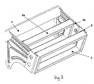
- the Fold-over plates 2 and the load distributor 3 are designed so that the Load distributor 3 on a flanged or inverted part the slip plates 2 is attached and in the event of an impact Position 3a passes, in which the faceplate 2 continues to roll is, whereby corresponding energy is reduced.
- the end position of the slip plate is designated 2a. This stands out characterized in that a larger part of the slip plate 2 is crimped.
- 1A and 1B are slip plates 2 and load distributors 3 on the passenger side and slip plates 9 and load distributor 10 shown on the driver side.
- 1A is the undeformed one State shown while Fig. 1B on the Passenger side shows the deformed state in which the Slip plates and the load distributors positions 2a and 3a have taken.
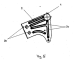
- the slip plates 2 have a height of approx. 100mm and is the moment of inertia around the X axis in Fig. 3 very large.
- the over the length of the slip plate in this Flanging running in the direction of the axis is very stiff and stands still normal on the sheet metal trim.
- the effects therefore negligible, since at most the Direction of deformation could be slightly oblique.
- connection point of the slip plates on the body side essential Install closer to the load distributor than with known ones Arrangements is the case because this is on the one hand laterally is arranged, and moreover a length translation insofar takes place as the displacement of the load distributor in the X direction in the event of an impact in a ratio of 2: 1 to Displacement of the flanging edge of the faceplate stands.
- Figs. 1A and 1B shown assembly from the body-in-white, i.e. the post A, namely the door jamb front right and left and limited the sheet metal parts are extended downwards in the middle and there screwed to the vehicle tunnel.
- This screw connection with the Vehicle tunnels are common in today's vehicles in order to Natural frequency of the cross member to increase and therefore represents does not represent any additional effort Thrust direction in the XY plane in Fig. 4, i.e. diagonally outwards or inside, is therefore no effect on the slip or Fearing behavior of the face plates to be feared.
- the knees move and legs of a vehicle occupant in a frontal impact circular along the dashed knee curve 6 around the ankle 5 as a fulcrum towards the Load distributor 3.
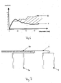
- the force curve 7 results, which is shown in FIG. 6.
- This course shows that in the device according to the invention a reduction in the level of force is possible, which at Use of known deformation elements with the force curve 8 not possible.
- the use of face plates with attached Load balancing has the further advantage that others Components can be fixed to the slip plates 2, so that the slip plates 2 are not necessarily additional components must, but the function of usual holding and connecting plates can take over with. It is also possible, for example the tunnel support that is between the central tube and the tunnel runs as a faceplate.
- the Load distributor 3 is preferably frame-shaped, so that he applies the forces directly to the face plates 2 forwards.
- slip plates 2 also leads to the fact that the installation space in the leg area is insignificantly reduced is, so that for example on the passenger side the full Glove box size can be retained.
Landscapes
- Engineering & Computer Science (AREA)
- Mechanical Engineering (AREA)
- Body Structure For Vehicles (AREA)
- Vibration Dampers (AREA)
Applications Claiming Priority (2)
| Application Number | Priority Date | Filing Date | Title |
|---|---|---|---|
| DE10240646A DE10240646A1 (de) | 2002-09-03 | 2002-09-03 | Vorrichtung zum Schützen der Beine eines Fahrzeuginsassen |
| DE10240646 | 2002-09-03 |
Publications (2)
| Publication Number | Publication Date |
|---|---|
| EP1398222A2 true EP1398222A2 (fr) | 2004-03-17 |
| EP1398222A3 EP1398222A3 (fr) | 2004-05-19 |
Family
ID=31724275
Family Applications (1)
| Application Number | Title | Priority Date | Filing Date |
|---|---|---|---|
| EP03016168A Withdrawn EP1398222A3 (fr) | 2002-09-03 | 2003-07-16 | Dispositif de protection des jambes d'un passager de véhicule |
Country Status (3)
| Country | Link |
|---|---|
| US (1) | US6948738B2 (fr) |
| EP (1) | EP1398222A3 (fr) |
| DE (1) | DE10240646A1 (fr) |
Cited By (1)
| Publication number | Priority date | Publication date | Assignee | Title |
|---|---|---|---|---|
| EP2070769A4 (fr) * | 2006-12-27 | 2010-09-01 | Calsonic Kansei Corp | Structure de fixation pour un appareil electronique embarque |
Families Citing this family (16)
| Publication number | Priority date | Publication date | Assignee | Title |
|---|---|---|---|---|
| US7128339B2 (en) * | 2002-10-10 | 2006-10-31 | Indus Concept & Engineering Llc | Automotive knee bolster installation and method of construction |
| US8172264B2 (en) * | 2002-10-10 | 2012-05-08 | Ayyakannu Mani | Automotive knee bolster installation and method of construction |
| US20060131861A1 (en) * | 2002-10-10 | 2006-06-22 | Ayyakannu Mani | Automotive knee bolster installation and method of construction |
| JP3994913B2 (ja) * | 2003-05-16 | 2007-10-24 | 日産自動車株式会社 | 車両用収納ボックスの取付構造 |
| US7393013B2 (en) * | 2003-09-05 | 2008-07-01 | Salflex Polymers Ltd. | Structural knee bolster |
| DE10360124A1 (de) * | 2003-12-20 | 2005-07-28 | Daimlerchrysler Ag | Knieaufprallelement für Kraftfahrzeuge |
| US7331606B2 (en) * | 2004-10-14 | 2008-02-19 | Delphi Technologies, Inc. | Knee bolster |
| US20060232055A1 (en) * | 2005-04-15 | 2006-10-19 | Visteon Global Technologies, Inc. | Energy absorbing structure |
| US7484792B2 (en) * | 2006-02-07 | 2009-02-03 | Toyota Motor Engineering & Manufacturing North America, Inc. | Glove box assembly exhibiting knee impact force transferring structure with respect to an associated vehicle dash/instrument panel and reinforcing bar |
| US7874587B2 (en) * | 2006-02-07 | 2011-01-25 | Toyota Motor Engineering & Manufacturing North America, Inc. | Glove box assembly exhibiting knee impact force transferring structure with respect to an associated vehicle dash/instrument panel and reinforcing bar and including removable strengthening ribs for tuning of crash safety characteristics |
| EP1857331B1 (fr) * | 2006-05-16 | 2010-03-31 | Ford Global Technologies, LLC | Dispositif de sécurité |
| US7735865B2 (en) * | 2007-07-19 | 2010-06-15 | Visteon Global Technologies, Inc. | Knee bolster assembly |
| US20100001568A1 (en) * | 2008-07-03 | 2010-01-07 | Dalton Trybus | Vehicle seat with cushion carrier |
| US8267428B2 (en) * | 2009-12-18 | 2012-09-18 | International Automotive Components Group North America, Inc | Energy absorbing countermeasure |
| US10093263B2 (en) * | 2015-07-16 | 2018-10-09 | Ford Global Technologies, Llc | Energy absorbing instrument panel component |
| US11040666B2 (en) * | 2019-02-22 | 2021-06-22 | Ford Global Technologies, Llc | Vehicle glove box bin |
Family Cites Families (19)
| Publication number | Priority date | Publication date | Assignee | Title |
|---|---|---|---|---|
| US4709943A (en) * | 1985-07-17 | 1987-12-01 | Mazda Motor Corporation | Knee protector structure for vehicle |
| JP2705775B2 (ja) * | 1987-06-18 | 1998-01-28 | 本田技研工業株式会社 | 車輌用膝部衝撃吸収装置 |
| JP2553224B2 (ja) * | 1990-05-22 | 1996-11-13 | 日産自動車株式会社 | 自動車用ニープロテクタ |
| US5096223A (en) * | 1990-12-26 | 1992-03-17 | Ford Motor Company | Energy absorbing bracket for interior panels |
| DE4206782A1 (de) * | 1991-03-16 | 1992-09-17 | Volkswagen Ag | Nach dem stuelpprinzip arbeitendes deformationselement |
| JPH04130585U (ja) * | 1991-05-24 | 1992-11-30 | マツダ株式会社 | 自動車のインストルメントパネル部構造 |
| US5273314A (en) * | 1991-10-17 | 1993-12-28 | Toyota Jidosha Kabushiki Kaisha | Supporting bracket for knee panel |
| DE4307836B4 (de) * | 1992-03-25 | 2005-09-29 | Volkswagen Ag | Träger zur Energieabsorption bei quer zu seiner Längsrichtung erfolgenden Stößen |
| JPH07172255A (ja) * | 1993-12-18 | 1995-07-11 | Suzuki Motor Corp | 自動車のニーボルスター装置 |
| US5518270A (en) * | 1994-03-30 | 1996-05-21 | Nissan Motor Co., Ltd. | Knee protector device for vehicle |
| US5370417A (en) * | 1994-04-18 | 1994-12-06 | Davidson Textron Inc. | Automotive knee bolster |
| DE19537408C1 (de) * | 1995-10-09 | 1996-12-05 | Daimler Benz Ag | Kraftwagenvorbau |
| US6296277B1 (en) * | 1998-05-18 | 2001-10-02 | Chrysler Corporation | Integral passenger restraint system |
| DE19853346A1 (de) * | 1998-11-19 | 2000-05-25 | Volkswagen Ag | Kniepolster-Vorrichtung für ein Kraftfahrzeug |
| US6139082A (en) * | 1998-12-09 | 2000-10-31 | Lear Automotive Dearborn, Inc. | Cross car beam with adjustable mounting locations |
| DE10060636A1 (de) | 2000-12-06 | 2002-07-04 | Euromotive Gmbh | Vorrichtung zum Aufnehmen von Stoßenergie |
| US6609727B2 (en) * | 2001-08-06 | 2003-08-26 | General Motors Corporation | Energy absorbing knee bolster assembly |
| DE10146495B4 (de) * | 2001-09-21 | 2005-10-20 | Porsche Ag | Kniestütze für Insassen |
| US6783156B2 (en) * | 2002-10-10 | 2004-08-31 | Lear Corporation | Passenger restraint |
-
2002
- 2002-09-03 DE DE10240646A patent/DE10240646A1/de not_active Ceased
-
2003
- 2003-07-16 EP EP03016168A patent/EP1398222A3/fr not_active Withdrawn
- 2003-09-03 US US10/653,135 patent/US6948738B2/en not_active Expired - Fee Related
Cited By (2)
| Publication number | Priority date | Publication date | Assignee | Title |
|---|---|---|---|---|
| EP2070769A4 (fr) * | 2006-12-27 | 2010-09-01 | Calsonic Kansei Corp | Structure de fixation pour un appareil electronique embarque |
| US8047571B2 (en) | 2006-12-27 | 2011-11-01 | Calsonic Kansei Corporation | Fixture structure for in-vehicle electronic apparatus |
Also Published As
| Publication number | Publication date |
|---|---|
| EP1398222A3 (fr) | 2004-05-19 |
| DE10240646A1 (de) | 2004-03-18 |
| US6948738B2 (en) | 2005-09-27 |
| US20040041385A1 (en) | 2004-03-04 |
Similar Documents
| Publication | Publication Date | Title |
|---|---|---|
| EP3668777B1 (fr) | Arrangement de longeron pour véhicule | |
| EP1981737B1 (fr) | Corps d absorption d énergie, dispositif de protection contre une collision, élément d habillage intérieur pour véhicule automobile et traverse | |
| DE69811639T2 (de) | Unterfahrschutzvorrichtung in fahrzeugen | |
| DE10240646A1 (de) | Vorrichtung zum Schützen der Beine eines Fahrzeuginsassen | |
| DE102016012183A1 (de) | Crashstruktur für ein Fahrzeug | |
| DE102008009964A1 (de) | Kollision-Detektorvorrichtung und Schutzsystem | |
| DE60130018T2 (de) | Anordnung zur schwächung einer konstruktion | |
| DE102011089027B4 (de) | Aktives Motorhauben-System für ein Fahrzeug | |
| DE102008013815A1 (de) | Kollision-Detektorvorrichtung, Fußgänger-Kollision-Detektoreinrichtung und Fußgänger-Schutzsystem | |
| DE4205032A1 (de) | Stossverzehrvorrichtung | |
| EP3558757B1 (fr) | Ensemble pare-chocs pour la zone frontale d'une voiture particulière | |
| WO2016083291A1 (fr) | Agencement de composants d'absorption de choc pour véhicule automobile | |
| DE102017211339B4 (de) | Bremskraftverstärkereinrichtung mit einem verformbaren Aktuator | |
| DE10130637A1 (de) | Unterfahrschutz für Lastkraftwagen und Omnibusse | |
| DE10060636A1 (de) | Vorrichtung zum Aufnehmen von Stoßenergie | |
| DE102017211337B4 (de) | Bremskraftverstärkereinrichtung mit einer mehrteiligen Befestigungsvorrichtung für den Bremskraftverstärker | |
| DE20209141U1 (de) | Griffeinrichtung für einen Fahrzeuginnenraum | |
| DE102017007400B4 (de) | Vorrichtung zur Verbindung einer A-, B- oder C-Säule eines Kraftfahrzeugs mit einer Tür | |
| DE102021004411A1 (de) | Fahrzeugtür mit einem Seitenaufprallschutzsystem | |
| DE102023121530B3 (de) | Vorrichtung zur Krafteinleitung in einen Rohbau eines Fahrzeugs beim Seitencrash | |
| DE102006044121A1 (de) | Sicherheitsvorrichtung für Fahrzeuge | |
| DE102024100337A1 (de) | Anordnung einer Instrumententafel an einer Tragstruktur für einen Kraftwagen | |
| DE102024003516A1 (de) | Fahrzeug | |
| DE102023116245A1 (de) | Schlosshalter für einen Kraftfahrzeug-Türverschluss | |
| DE102024201576A1 (de) | Kraftfahrzeug mit Frunk |
Legal Events
| Date | Code | Title | Description |
|---|---|---|---|
| PUAI | Public reference made under article 153(3) epc to a published international application that has entered the european phase |
Free format text: ORIGINAL CODE: 0009012 |
|
| AK | Designated contracting states |
Kind code of ref document: A2 Designated state(s): AT BE BG CH CY CZ DE DK EE ES FI FR GB GR HU IE IT LI LU MC NL PT RO SE SI SK TR |
|
| AX | Request for extension of the european patent |
Extension state: AL LT LV MK |
|
| PUAL | Search report despatched |
Free format text: ORIGINAL CODE: 0009013 |
|
| AK | Designated contracting states |
Kind code of ref document: A3 Designated state(s): AT BE BG CH CY CZ DE DK EE ES FI FR GB GR HU IE IT LI LU MC NL PT RO SE SI SK TR |
|
| AX | Request for extension of the european patent |
Extension state: AL LT LV MK |
|
| 17P | Request for examination filed |
Effective date: 20041117 |
|
| AKX | Designation fees paid |
Designated state(s): DE FR GB IT SE |
|
| 17Q | First examination report despatched |
Effective date: 20050304 |
|
| 17Q | First examination report despatched |
Effective date: 20050304 |
|
| STAA | Information on the status of an ep patent application or granted ep patent |
Free format text: STATUS: THE APPLICATION IS DEEMED TO BE WITHDRAWN |
|
| 18D | Application deemed to be withdrawn |
Effective date: 20070220 |