EP1398508A2 - Pompe à tube d'entrefer - Google Patents
Pompe à tube d'entrefer Download PDFInfo
- Publication number
- EP1398508A2 EP1398508A2 EP03250048A EP03250048A EP1398508A2 EP 1398508 A2 EP1398508 A2 EP 1398508A2 EP 03250048 A EP03250048 A EP 03250048A EP 03250048 A EP03250048 A EP 03250048A EP 1398508 A2 EP1398508 A2 EP 1398508A2
- Authority
- EP
- European Patent Office
- Prior art keywords
- fluid
- chamber
- pump
- rotor
- stator
- Prior art date
- Legal status (The legal status is an assumption and is not a legal conclusion. Google has not performed a legal analysis and makes no representation as to the accuracy of the status listed.)
- Granted
Links
- 239000012530 fluid Substances 0.000 claims abstract description 86
- 238000001914 filtration Methods 0.000 claims abstract description 12
- 238000001816 cooling Methods 0.000 claims description 18
- 239000000463 material Substances 0.000 claims description 9
- XEEYBQQBJWHFJM-UHFFFAOYSA-N Iron Chemical compound [Fe] XEEYBQQBJWHFJM-UHFFFAOYSA-N 0.000 claims description 6
- 230000005540 biological transmission Effects 0.000 claims description 5
- 238000004891 communication Methods 0.000 claims description 3
- 229910052742 iron Inorganic materials 0.000 claims description 3
- 229920000642 polymer Polymers 0.000 claims description 3
- 238000007789 sealing Methods 0.000 claims description 3
- XAGFODPZIPBFFR-UHFFFAOYSA-N aluminium Chemical compound [Al] XAGFODPZIPBFFR-UHFFFAOYSA-N 0.000 claims description 2
- 229910052782 aluminium Inorganic materials 0.000 claims description 2
- 238000000926 separation method Methods 0.000 claims description 2
- 238000004064 recycling Methods 0.000 claims 1
- 238000011144 upstream manufacturing Methods 0.000 claims 1
- 239000007788 liquid Substances 0.000 description 11
- 230000006698 induction Effects 0.000 description 3
- 239000000314 lubricant Substances 0.000 description 3
- 238000004519 manufacturing process Methods 0.000 description 3
- 230000007246 mechanism Effects 0.000 description 3
- 230000009471 action Effects 0.000 description 2
- 230000008901 benefit Effects 0.000 description 2
- 230000000694 effects Effects 0.000 description 2
- 238000009413 insulation Methods 0.000 description 2
- 238000005461 lubrication Methods 0.000 description 2
- 238000012423 maintenance Methods 0.000 description 2
- 230000009467 reduction Effects 0.000 description 2
- 238000012800 visualization Methods 0.000 description 2
- 230000002411 adverse Effects 0.000 description 1
- 239000004411 aluminium Substances 0.000 description 1
- 239000002826 coolant Substances 0.000 description 1
- 230000007797 corrosion Effects 0.000 description 1
- 238000005260 corrosion Methods 0.000 description 1
- 238000013461 design Methods 0.000 description 1
- 238000007667 floating Methods 0.000 description 1
- 239000004519 grease Substances 0.000 description 1
- 238000007654 immersion Methods 0.000 description 1
- 230000001939 inductive effect Effects 0.000 description 1
- 238000009434 installation Methods 0.000 description 1
- 239000000696 magnetic material Substances 0.000 description 1
- 230000009972 noncorrosive effect Effects 0.000 description 1
- 238000005086 pumping Methods 0.000 description 1
- 238000009423 ventilation Methods 0.000 description 1
- XLYOFNOQVPJJNP-UHFFFAOYSA-N water Substances O XLYOFNOQVPJJNP-UHFFFAOYSA-N 0.000 description 1
Images



Classifications
-
- F—MECHANICAL ENGINEERING; LIGHTING; HEATING; WEAPONS; BLASTING
- F04—POSITIVE - DISPLACEMENT MACHINES FOR LIQUIDS; PUMPS FOR LIQUIDS OR ELASTIC FLUIDS
- F04D—NON-POSITIVE-DISPLACEMENT PUMPS
- F04D13/00—Pumping installations or systems
- F04D13/02—Units comprising pumps and their driving means
- F04D13/06—Units comprising pumps and their driving means the pump being electrically driven
- F04D13/0646—Units comprising pumps and their driving means the pump being electrically driven the hollow pump or motor shaft being the conduit for the working fluid
-
- F—MECHANICAL ENGINEERING; LIGHTING; HEATING; WEAPONS; BLASTING
- F04—POSITIVE - DISPLACEMENT MACHINES FOR LIQUIDS; PUMPS FOR LIQUIDS OR ELASTIC FLUIDS
- F04D—NON-POSITIVE-DISPLACEMENT PUMPS
- F04D29/00—Details, component parts, or accessories
- F04D29/58—Cooling; Heating; Diminishing heat transfer
- F04D29/5806—Cooling the drive system
-
- F—MECHANICAL ENGINEERING; LIGHTING; HEATING; WEAPONS; BLASTING
- F04—POSITIVE - DISPLACEMENT MACHINES FOR LIQUIDS; PUMPS FOR LIQUIDS OR ELASTIC FLUIDS
- F04D—NON-POSITIVE-DISPLACEMENT PUMPS
- F04D29/00—Details, component parts, or accessories
- F04D29/70—Suction grids; Strainers; Dust separation; Cleaning
- F04D29/708—Suction grids; Strainers; Dust separation; Cleaning specially for liquid pumps
Definitions
- the present invention relates to a pump, more specifically, a hydraulic one.
- electro-mechanical pumps used for driving fluids generally constituted of a chamber containing the electro-magnetic part, basically comprising the stator and the rotor armature, as well as another chamber with a hydraulic part, basically formed of the hydraulic turbine that drives the liquid.
- the electro-magnetic and hydraulic chambers need to be insulated from each other so as to prevent the liquid from reaching the stator and the rotor, causing short-circuits and even irreparable damage.
- several mechanical apparatus are required, such as an axle, roller bearings, bearing journals, cooling systems, hydraulic seals, among others.
- roller bearing journals for instance, have the function of supporting the rotor axle, on which the rotor cage is mounted, so that, when the latter is induced by magnetic forces from the stator, the rotor turns, assisted by these bearings.
- the journals are lubricated with oil or grease so as to decrease friction and wear between the parts in contact.
- One end of the rotor axle is connected to the hydraulic turbine, formed of blades, which, upon induction of the rotor, begins a rotational movement driving the liquid to be pumped.
- cooling systems are used, usually constituted of ventilators.
- Such cooling systems generally comprise propellers coupled to the end of the rotor axle, outside the pump and opposed to the hydraulic pump, which, taking advantage of the rotation of the rotor, turns to cool both the stator and the rotor.
- the pumps of the prior art depend upon the perfect functioning of the mechanical seals to prevent the liquid from passing from the hydraulic chamber into the electro-magnetic chamber. As already mentioned, this undesirable contact of the liquid with the stator and rotor may cause short-circuits, as well as a decrease in the lubrication of the journals, resulting in possible seizure of the rotor.
- a preferred embodiment of the present invention simplifies the composition of a traditional pump by eliminating sealings, such as mechanical seals or gaskets, as well as roller bearings, axles and external cooling systems, such as ventilators, thereby reducing the chance of the pump being damaged.
- This new pump motor further provides cooling of the stator-rotor assembly by circulating the pumped fluid itself, as described in Brazilian Patent Application No. PI 0004206-4 which is incorporated herein by reference.
- a preferred embodiment of the invention also provides a new pump that is more compact than the present ones, easy to manufacture and assemble, by virtue of its smaller number of components, thus resulting in better automation and cost reduction.
- Another feature of a preferred embodiment of the present invention is to provide a pump design that is more efficient, that is, presenting lower energy loss.
- the invention aims at providing a safer, more protected and corrosion proof pump motor, enabling immersion and installation in environments that are aggressive and without cooling.
- a further feature of a preferred embodiment of the present invention is to provide a pump with a very low noise level and lubrication provided by the circulating fluid itself.
- the present invention preferably comprises a pump that has a casing, having at least one first hermetically sealed chamber and at least one second chamber adjacent to said first chamber, provided with a fluid passage and having an inlet and an outlet for fluids. Said chambers are separated by means of walls, preferably made of injected polymer.
- the pump further comprises a stator located in the first chamber.
- the stator is in a position adjacent to the walls that separate the first chamber from the second, so that the fluid circulating through the second chamber will cool it by heat transmission.
- An integral rotor-turbine assembly preferably wholly located in the second chamber, is provided, and at least a portion of said assembly is positioned concentrically in relation to the stator.
- This assembly is induced by the stator to drive a fluid from the inlet to the outlet.
- at least a fluid film is maintained around the assembly, in order to bring about high performance/accurate rotation with minimum friction and without any need for journals.
- the fluid film works as a bearing to support the assembly.
- the space between said assembly and the stator called a gap, is substantially filled with said walls of the first and second chambers, including, furthermore, the fluid film circulating between them.
- a metallic component called the rotor cage, preferably composed of iron and aluminium, capable of being induced by the stator, is provided inside the hermetically sealed assembly.
- such an assembly is made from polymeric material and is additionally bored through to provide a passage for the turbine inside the rotor.
- the turbine of said assembly is composed of turbine blades to centrifuge the fluids. In this way, upon functioning of a possible embodiment of the pump, the fluid, after passing through the inlet of the second chamber, goes into the rotor-turbine assembly, passes through the internal passageway and, after reaching the turbine blades, is driven towards the outlet.
- the circulating fluid is also used as a lubricant.
- a film of circulating fluid will pass between the walls of the second chamber and the rotor-turbine assembly, allowing the latter to make a floating rotary movement within the second chamber by virtue of the inducing forces.
- the first chamber provides a circular path with a filtration zone, whereby the fluid, upon entry via the pump's fluid inlet, circulates through a portion of the first chamber, passes through a filter and proceeds to a turbine assembly, after which it is propelled to the fluid outlet, as well as allowing part of the fluid to enter a portion of the second chamber, providing cooling of the pump motor.
- the present pump further incorporates front and rear covers for the principal housing.
- the pump of the present invention provides a simpler configuration with less expensive manufacture, since it is basically composed of an induction means and a movement-transmission means similar to those of the prior art, such as stators and rotors, which eliminate the use of a ventilator, as well as roller bearings, axles and mechanical seals.
- Figure 1 shows a present-day pump, encountered in the prior art, comprising a coiled stator 4, a rotor 5 and roller bearings 3, which support the axle 9 on which the cage of said rotor 5 is mounted.
- the axle 9 will be responsible for transmitting driving force from the rotor 5 by means of induction of the magnetic field of the stator 4.
- a ventilator 1 which is responsible for cooling the stator-rotor assembly, and of covers 2 located on both sides of the rotor 5, which support said roller bearings.
- the rotor 5 has to be perfectly centered with respect to the stator 4, so as to avoid contact between their magnetic iron.
- this space between the rotor 5 and the stator 4, called a gap, is filled with air.
- Figure 1 further illustrates mechanical seals 8, which are widely used in the pump motors of the prior art, to guarantee insulation and separation between the electric part and the hydraulic part of the pump motor, the hydraulic part being constituted of the turbine 7 and the volute 6.
- FIG 2 illustrates a preferred embodiment of the present invention, in which some of the elements shown in figure 1 are absent.
- This embodiment illustrates a pump 10 comprising a casing 14 having a first hermetically sealed chamber 19 and a second internal chamber 17 with at least one inlet 15 and one outlet 16 defining the passageway 18 between said inlet and outlet.
- the casing 14 may be made from a polymeric material or any other type of material suitable for the specified conditions, including bad weather.
- An integral rotor-turbine assembly 11 is located in the chamber 17 to drive the fluids that pass through said chamber.
- This assembly is made from a polymeric material and, in addition, is bored through to define a passageway for the turbine inside the rotor.
- the turbine of said assembly is composed of blades for centrifuging the fluids.
- the casing 14 also has a first chamber 19, hermetically sealed from the fluids that circulate through the second chamber 17. Both the external walls of the casing and the walls that separate the second chamber 17 from the first chamber 19 are formed of injectable polymeric material.
- the stator 12 which may be any one of those known from the prior art, is installed in this first chamber 19 to induce, by means of a magnetic field, the driving of the rotor-turbine assembly 11, located in the second chamber 17 of fluid circulation.
- This embodiment of the pump of the present invention also has its second chamber 17 defining passageways other than that going from the inlet to the outlet, so that a portion of the fluids will circulate through this chamber. Such passageways in this embodiment cause the fluid to circulate around the first chamber 19, cooling the stator 12 located therein by heat transmission.
- a small portion of the fluid that enters inlet 15 and circulates through the second chamber 17 passes through the communication means 13 between one of the walls of the second chamber 17 and the rotor-turbine assembly 11, creating a constant fluid film, which enables this assembly to turn freely submerged in the liquid, without having any contact with the walls of the second chamber 17 while the pump is functioning.
- the fluid film works as a bearing to support the assembly 11 and, at the same time, as a lubricant that virtually eliminates friction between the walls of the second chamber and of the assembly 11, further resulting in a very low noise level.
- the magnetic field created by the stator 12 maintains the former in a balanced position around its axle, so that, upon rotational movement, the magnetic forces prevent the assembly from contacting the walls of the second chamber 17.
- the second chamber 17 has passageways that enable the liquid to circulate through it, a reduction in noise level is achieved, and this also eliminates the need for industrial lubricants and external cooling systems. Since, in a preferred embodiment of the pump, the pump is basically composed of an injectable polymeric material and there is a decrease in the number of components (i.e. does not include seals) in comparison with those of the prior art, it becomes simpler and less expensive to assemble. In addition, the energy losses are minimized by the low friction between the rotor-turbine assembly 11 and the walls of the second chamber 17.
- Another aspect of the present invention is that the space between the stator 4 and the rotor 5 of the pumps of the prior art, the so-called gaps, are filled with air.
- the polymeric wall of both the second chamber 17 and the rotor-turbine assembly 11 providing accurate centering of the magnetic materials of the stator 12 and the assembly 11, as well as a better balanced position of the latter around its axle, so that, upon rotation, contact with the walls of the second chamber 17 will be avoided.
- the present invention also provides a non-corrosive pump, since only the surface covered with polymer will have contact with the fluid. Therefore, the latter may be aggressive without causing any damage to the pump motor.
- the pump of the present invention since the liquid itself is used as a coolant, the pump of the present invention may be installed in environments without ventilation or even submerged.
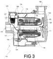
- Figure 3 illustrates a second preferred embodiment of the present invention, where one can observe the absence of some components shown in Figure 1, the latter representing the state of the art in pumps.
- This embodiment illustrates pump 110 comprising housing 114, its first chamber 119 impervious to liquids; second chamber 117 defining a fluid path, and filtration zone 120 positioned in the outlet from chamber 119 and directed towards the path between the inlet and outlet of passage 118, this providing communication for the fluid between inlet 115 and outlet 116.
- Housing 114 may be made of polymeric material or of any other type suitable to cope even with adverse conditions, as determined.
- this pump consists of covers, both frontal 121 and rear 122 for housing 114, these allowing easy access to the pump mechanism for eventual maintenance and/or part replacement operations.
- this second embodiment provides a new technical effect by the provision of chamber 119 and filter 120.
- Such a new technical effect lies in the filtration of the fluid in utilizations that require pumping of a fluid that is already treated, as well as in obtaining enhanced cooling by heat exchange produced by the proximity of chambers 119 and 117, through which the fluid circulates, with the stator assembly of the pump.
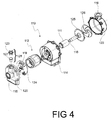
- FIG 4 shows an exploded perspective view of the pump.
- pump 110 possesses cover 121, in which the referred filtration zone 120 is located, the latter housing removable filter assembly 128.
- This filter assembly 128 comprises filter cover 123 and filter element 127.
- Wall 124, enclosing cover 121, defines portion 119a (Fig. 5) of first chamber 119 in conjunction with housing 114.
- the stator assembly is represented by reference 112. Inside principal housing 114, the separating walls for stator assembly 112 are illustrated.
- a rotor, as described in figure 2, is also shown in the referred figure 3 with reference 111.
- Said rotor 111 is integrally incorporated with turbine 125, these being separated in this figure in order to facilitate visualization of the whole assembly.
- Passage 118 mentioned previously, is also depicted in this figure, inside the turbine pipe 125. It also shows disc 126 with the turbine blades, responsible for impulsion of the fluid, for instance water, towards fluid outlet 116, as well as the inside of second chamber 117.
- cover 122 responsible for closing the principal housing, is shown.
- figure 5 shows the course of the fluid inside pump 110 in accordance with the second preferred embodiment of the invention, this course being represented by arrows.
- the fluid Upon entry to the pump via inlet 115, the fluid circulates in portion 119, providing initial cooling for the motor, passes through filtration zone 120 and then portion 119a towards passage 118, inside the rotor and turbine assembly.
- the fluid is propelled into second chamber 117, after which it goes to pump outlet 116.
- Part of the fluid propelled by the rotor-turbine assembly circulates in second chamber 117, producing a second cooling action for the motor.
- This fluid also runs along passage 113, forming a film between the stator and the rotor so as to cool the gap region of the motor, and, especially to avoid friction and noise generated by the rotation of the rotor.
- the fluid that runs along referred passage 113 is then returned to passage 118, to be propelled once more by the rotor-turbine assembly in chamber 117.
Landscapes
- Engineering & Computer Science (AREA)
- Mechanical Engineering (AREA)
- General Engineering & Computer Science (AREA)
- Physics & Mathematics (AREA)
- Thermal Sciences (AREA)
- Structures Of Non-Positive Displacement Pumps (AREA)
- Containers And Packaging Bodies Having A Special Means To Remove Contents (AREA)
- Rotary Pumps (AREA)
Applications Claiming Priority (3)
| Application Number | Priority Date | Filing Date | Title |
|---|---|---|---|
| BR0103034 | 2001-07-16 | ||
| BRPI0103034-5A BR0103034B1 (pt) | 2001-07-16 | 2001-07-16 | bomba. |
| BR0203034 | 2002-09-16 |
Publications (3)
| Publication Number | Publication Date |
|---|---|
| EP1398508A2 true EP1398508A2 (fr) | 2004-03-17 |
| EP1398508A3 EP1398508A3 (fr) | 2004-09-01 |
| EP1398508B1 EP1398508B1 (fr) | 2010-12-15 |
Family
ID=3947710
Family Applications (2)
| Application Number | Title | Priority Date | Filing Date |
|---|---|---|---|
| EP02250460.9A Expired - Lifetime EP1277965B1 (fr) | 2001-07-16 | 2002-01-23 | Pompe centrifuge |
| EP03250048A Expired - Lifetime EP1398508B1 (fr) | 2001-07-16 | 2003-01-03 | Pompe à tube d'entrefer |
Family Applications Before (1)
| Application Number | Title | Priority Date | Filing Date |
|---|---|---|---|
| EP02250460.9A Expired - Lifetime EP1277965B1 (fr) | 2001-07-16 | 2002-01-23 | Pompe centrifuge |
Country Status (13)
| Country | Link |
|---|---|
| US (1) | US20030012648A1 (fr) |
| EP (2) | EP1277965B1 (fr) |
| JP (2) | JP4180853B2 (fr) |
| AR (1) | AR030789A1 (fr) |
| AT (1) | ATE491886T1 (fr) |
| AU (2) | AU2002300182B2 (fr) |
| BR (1) | BR0103034B1 (fr) |
| CA (2) | CA2393243C (fr) |
| DE (1) | DE60335328D1 (fr) |
| DK (1) | DK1398508T3 (fr) |
| ES (2) | ES2612908T3 (fr) |
| MX (2) | MXPA02006940A (fr) |
| PT (2) | PT1277965T (fr) |
Cited By (5)
| Publication number | Priority date | Publication date | Assignee | Title |
|---|---|---|---|---|
| US7048518B2 (en) | 2001-07-16 | 2006-05-23 | Eberle Equipamentos E Processos S.A. | Pump |
| EP1757816A2 (fr) | 2005-08-26 | 2007-02-28 | Wilo Ag | Dispositif pour pompes |
| DE102006023379A1 (de) * | 2006-05-17 | 2007-11-22 | Al-Ko Kober Ag | Flüssigkeitspumpe |
| RU2548698C2 (ru) * | 2013-03-01 | 2015-04-20 | Открытое акционерное общество "Информационные спутниковые системы" имени академика М.Ф. Решетнёва" | Электронасосный агрегат |
| RU181506U1 (ru) * | 2017-04-10 | 2018-07-17 | Владислав Савельевич Медведев | Ротор электродвигателя герметичного электронасоса с полым валом |
Families Citing this family (10)
| Publication number | Priority date | Publication date | Assignee | Title |
|---|---|---|---|---|
| JP5371939B2 (ja) * | 2010-12-07 | 2013-12-18 | 株式会社市丸技研 | 流体送り装置及びタイヤ加硫装置 |
| CN102828998B (zh) * | 2012-08-29 | 2014-12-10 | 三一重工股份有限公司 | 一种发动机水泵及装设有该水泵的发动机、工程机械 |
| BR102014021617B1 (pt) | 2014-09-01 | 2023-04-11 | Mundial S/A Produtos De Consumo | Motobomba de mancal flutuante arrefecida por um fluido circulante |
| US10551498B2 (en) | 2015-05-21 | 2020-02-04 | Navico Holding As | Wireless sonar device |
| US9759813B2 (en) | 2015-06-22 | 2017-09-12 | Appetite Lab Inc. | Devices and methods for locating and visualizing underwater objects |
| EP3156663B1 (fr) * | 2015-10-15 | 2019-07-24 | Grundfos Holding A/S | Groupe pompe centrifuge |
| CN106704208A (zh) * | 2017-03-06 | 2017-05-24 | 威隼汽车科技(宁波)有限公司 | 一种汽车电子水泵 |
| CN114109907A (zh) * | 2020-08-27 | 2022-03-01 | 芜湖美的厨卫电器制造有限公司 | 泵盖、水泵和热水器 |
| CN112283166B (zh) * | 2020-11-09 | 2022-06-24 | 江苏优格曼航空科技有限公司 | 一种用于高速磁悬浮风机的易安装机壳结构 |
| CN117450114B (zh) * | 2023-11-21 | 2024-04-05 | 湖南新安特风机有限公司 | 消防系统智能风机 |
Family Cites Families (9)
| Publication number | Priority date | Publication date | Assignee | Title |
|---|---|---|---|---|
| GB485225A (en) * | 1936-02-29 | 1938-05-17 | Hans Moser | Improvements in or relating to electric motors |
| GB1320841A (en) * | 1971-01-04 | 1973-06-20 | Matsushita Electric Industrial Co Ltd | Motor driven pump |
| CH564155A5 (fr) * | 1972-06-22 | 1975-07-15 | Bauknecht Gmbh G | |
| DE3822897A1 (de) * | 1988-07-06 | 1990-01-11 | Webasto Ag Fahrzeugtechnik | Umwaelzpumpe |
| US5990588A (en) * | 1996-12-13 | 1999-11-23 | General Electric Company | Induction motor driven seal-less pump |
| US6068455A (en) * | 1997-03-20 | 2000-05-30 | B/E Aerospace | Long life pump system |
| US5921683A (en) * | 1997-09-12 | 1999-07-13 | United Technologies Corporation | Bearing arrangement for air cycle machine |
| US5997261A (en) * | 1997-10-31 | 1999-12-07 | Siemens Canada Limited | Pump motor having fluid cooling system |
| DE10108810A1 (de) * | 2001-02-16 | 2002-08-29 | Berlin Heart Ag | Vorrichtung zur axialen Förderung von Flüssigkeiten |
-
2001
- 2001-07-16 BR BRPI0103034-5A patent/BR0103034B1/pt not_active IP Right Cessation
- 2001-09-21 AR ARP010104469A patent/AR030789A1/es active IP Right Grant
-
2002
- 2002-01-17 US US10/050,033 patent/US20030012648A1/en not_active Abandoned
- 2002-01-23 PT PT2250460T patent/PT1277965T/pt unknown
- 2002-01-23 ES ES02250460.9T patent/ES2612908T3/es not_active Expired - Lifetime
- 2002-01-23 EP EP02250460.9A patent/EP1277965B1/fr not_active Expired - Lifetime
- 2002-07-12 CA CA002393243A patent/CA2393243C/fr not_active Expired - Lifetime
- 2002-07-15 MX MXPA02006940A patent/MXPA02006940A/es active IP Right Grant
- 2002-07-16 JP JP2002207243A patent/JP4180853B2/ja not_active Expired - Fee Related
- 2002-07-16 AU AU2002300182A patent/AU2002300182B2/en not_active Ceased
-
2003
- 2003-01-03 AT AT03250048T patent/ATE491886T1/de active
- 2003-01-03 EP EP03250048A patent/EP1398508B1/fr not_active Expired - Lifetime
- 2003-01-03 ES ES03250048T patent/ES2358012T3/es not_active Expired - Lifetime
- 2003-01-03 DE DE60335328T patent/DE60335328D1/de not_active Expired - Lifetime
- 2003-01-03 PT PT03250048T patent/PT1398508E/pt unknown
- 2003-01-03 DK DK03250048.0T patent/DK1398508T3/da active
- 2003-01-13 CA CA002416085A patent/CA2416085A1/fr not_active Abandoned
- 2003-01-14 MX MXPA03000417A patent/MXPA03000417A/es active IP Right Grant
- 2003-01-16 AU AU2003200128A patent/AU2003200128B2/en not_active Ceased
- 2003-01-27 JP JP2003017404A patent/JP2004108353A/ja active Pending
Cited By (7)
| Publication number | Priority date | Publication date | Assignee | Title |
|---|---|---|---|---|
| US7048518B2 (en) | 2001-07-16 | 2006-05-23 | Eberle Equipamentos E Processos S.A. | Pump |
| EP1757816A2 (fr) | 2005-08-26 | 2007-02-28 | Wilo Ag | Dispositif pour pompes |
| EP1757816A3 (fr) * | 2005-08-26 | 2008-06-04 | Wilo Ag | Dispositif pour pompes |
| DE102006023379A1 (de) * | 2006-05-17 | 2007-11-22 | Al-Ko Kober Ag | Flüssigkeitspumpe |
| DE102006023379B4 (de) * | 2006-05-17 | 2013-10-02 | Al-Ko Kober Ag | Flüssigkeitspumpe |
| RU2548698C2 (ru) * | 2013-03-01 | 2015-04-20 | Открытое акционерное общество "Информационные спутниковые системы" имени академика М.Ф. Решетнёва" | Электронасосный агрегат |
| RU181506U1 (ru) * | 2017-04-10 | 2018-07-17 | Владислав Савельевич Медведев | Ротор электродвигателя герметичного электронасоса с полым валом |
Also Published As
| Publication number | Publication date |
|---|---|
| AR030789A1 (es) | 2003-09-03 |
| JP4180853B2 (ja) | 2008-11-12 |
| ES2358012T3 (es) | 2011-05-04 |
| EP1277965A2 (fr) | 2003-01-22 |
| EP1398508B1 (fr) | 2010-12-15 |
| JP2004108353A (ja) | 2004-04-08 |
| MXPA03000417A (es) | 2004-12-09 |
| DE60335328D1 (de) | 2011-01-27 |
| EP1277965B1 (fr) | 2016-11-02 |
| HK1063498A1 (en) | 2004-12-31 |
| AU2003200128B2 (en) | 2009-07-16 |
| CA2416085A1 (fr) | 2004-03-16 |
| BR0103034B1 (pt) | 2009-05-05 |
| CA2393243A1 (fr) | 2003-01-16 |
| BR0103034C1 (pt) | 2003-11-04 |
| BR0103034A (pt) | 2003-07-29 |
| ATE491886T1 (de) | 2011-01-15 |
| PT1398508E (pt) | 2011-03-15 |
| PT1277965T (pt) | 2017-02-13 |
| DK1398508T3 (da) | 2011-03-28 |
| MXPA02006940A (es) | 2004-12-13 |
| ES2612908T3 (es) | 2017-05-19 |
| AU2002300182B2 (en) | 2008-01-10 |
| AU2003200128A1 (en) | 2004-04-01 |
| CA2393243C (fr) | 2008-10-14 |
| EP1277965A3 (fr) | 2004-08-04 |
| JP2003097482A (ja) | 2003-04-03 |
| US20030012648A1 (en) | 2003-01-16 |
| EP1398508A3 (fr) | 2004-09-01 |
Similar Documents
| Publication | Publication Date | Title |
|---|---|---|
| EP1398508B1 (fr) | Pompe à tube d'entrefer | |
| US5549447A (en) | System for cooling a centrifugal pump | |
| KR20150092330A (ko) | 액체를 펌핑하기 위한 펌프의 냉각 장치 | |
| US7048518B2 (en) | Pump | |
| USRE37233E1 (en) | Integral motor centrifugal pump | |
| JP4059416B2 (ja) | 一体型モータポンプ | |
| EP1200736A1 (fr) | Pompe en ligne sans axe pour canalisation equipee d'un rotor a gaine | |
| JP2000303986A5 (fr) | ||
| US9587638B2 (en) | Drive unit for a submersible oil pump, with a fluid passage allowing the fluid in the motor housing to be discharged to the ambient enviroment | |
| JPH11325258A (ja) | シ―ル装置 | |
| JP4828860B2 (ja) | 回転電機 | |
| JP2018040320A (ja) | オイルフリースクリュ圧縮機 | |
| EP0013869A1 (fr) | Dispositif pour refroidir un moteur étanche submersible | |
| EP3759351B1 (fr) | Système de pompage à vide comportant une pompe à vide et son moteur | |
| EP2710719B2 (fr) | Équipement d'accouplement de commande magnétique | |
| WO2016033667A1 (fr) | Pompe à moteur à palier flottant refroidie par fluide circulant | |
| JP2003003984A (ja) | キャンドポンプ | |
| JP2020162204A (ja) | 回転電機および回転電機システム | |
| EP0178087A1 (fr) | Moyens de refroidissement pour tête de pompe submersible | |
| HK1063498B (en) | Canned centrifugal pump | |
| CN212130894U (zh) | 一种水泵双水冷结构 | |
| KR102591684B1 (ko) | 베어링의 윤활이 향상된 모터 | |
| CN220527823U (zh) | 旋翼驱动电机及飞行器 | |
| CN223231015U (zh) | 一种无油泵转子油冷电机减速器总成 | |
| JPH0631198Y2 (ja) | 無漏洩ポンプの軸受装置 |
Legal Events
| Date | Code | Title | Description |
|---|---|---|---|
| PUAI | Public reference made under article 153(3) epc to a published international application that has entered the european phase |
Free format text: ORIGINAL CODE: 0009012 |
|
| AK | Designated contracting states |
Kind code of ref document: A2 Designated state(s): AT BE BG CH CY CZ DE DK EE ES FI FR GB GR HU IE IT LI LU MC NL PT SE SI SK TR |
|
| AX | Request for extension of the european patent |
Extension state: AL LT LV MK RO |
|
| PUAL | Search report despatched |
Free format text: ORIGINAL CODE: 0009013 |
|
| AK | Designated contracting states |
Kind code of ref document: A3 Designated state(s): AT BE BG CH CY CZ DE DK EE ES FI FR GB GR HU IE IT LI LU MC NL PT SE SI SK TR |
|
| AX | Request for extension of the european patent |
Extension state: AL LT LV MK RO |
|
| RIC1 | Information provided on ipc code assigned before grant |
Ipc: 7F 04D 29/04 B Ipc: 7F 04D 13/06 A |
|
| REG | Reference to a national code |
Ref country code: HK Ref legal event code: DE Ref document number: 1063498 Country of ref document: HK |
|
| 17P | Request for examination filed |
Effective date: 20050203 |
|
| AKX | Designation fees paid |
Designated state(s): AT BE BG CH CY CZ DE DK EE ES FI FR GB GR HU IE IT LI LU MC NL PT SE SI SK TR |
|
| 17Q | First examination report despatched |
Effective date: 20070208 |
|
| GRAP | Despatch of communication of intention to grant a patent |
Free format text: ORIGINAL CODE: EPIDOSNIGR1 |
|
| GRAS | Grant fee paid |
Free format text: ORIGINAL CODE: EPIDOSNIGR3 |
|
| GRAA | (expected) grant |
Free format text: ORIGINAL CODE: 0009210 |
|
| AK | Designated contracting states |
Kind code of ref document: B1 Designated state(s): AT BE BG CH CY CZ DE DK EE ES FI FR GB GR HU IE IT LI LU MC NL PT SE SI SK TR |
|
| REG | Reference to a national code |
Ref country code: GB Ref legal event code: FG4D Ref country code: CH Ref legal event code: EP |
|
| REG | Reference to a national code |
Ref country code: IE Ref legal event code: FG4D |
|
| REF | Corresponds to: |
Ref document number: 60335328 Country of ref document: DE Date of ref document: 20110127 Kind code of ref document: P |
|
| REG | Reference to a national code |
Ref country code: PT Ref legal event code: SC4A Free format text: AVAILABILITY OF NATIONAL TRANSLATION Effective date: 20110307 |
|
| REG | Reference to a national code |
Ref country code: NL Ref legal event code: T3 |
|
| REG | Reference to a national code |
Ref country code: DK Ref legal event code: T3 |
|
| REG | Reference to a national code |
Ref country code: SE Ref legal event code: TRGR |
|
| REG | Reference to a national code |
Ref country code: CH Ref legal event code: NV Representative=s name: RENTSCH & PARTNER |
|
| REG | Reference to a national code |
Ref country code: ES Ref legal event code: FG2A Ref document number: 2358012 Country of ref document: ES Kind code of ref document: T3 Effective date: 20110504 |
|
| PG25 | Lapsed in a contracting state [announced via postgrant information from national office to epo] |
Ref country code: SI Free format text: LAPSE BECAUSE OF FAILURE TO SUBMIT A TRANSLATION OF THE DESCRIPTION OR TO PAY THE FEE WITHIN THE PRESCRIBED TIME-LIMIT Effective date: 20101215 Ref country code: CY Free format text: LAPSE BECAUSE OF FAILURE TO SUBMIT A TRANSLATION OF THE DESCRIPTION OR TO PAY THE FEE WITHIN THE PRESCRIBED TIME-LIMIT Effective date: 20101215 Ref country code: BG Free format text: LAPSE BECAUSE OF FAILURE TO SUBMIT A TRANSLATION OF THE DESCRIPTION OR TO PAY THE FEE WITHIN THE PRESCRIBED TIME-LIMIT Effective date: 20110315 |
|
| REG | Reference to a national code |
Ref country code: CH Ref legal event code: PFA Owner name: EBERLE EQUIPAMENTOS E PROCESSOS S.A. Free format text: EBERLE EQUIPAMENTOS E PROCESSOS S.A.#RUA ANA CATHERINA CANALLI, 1.101#CAXIAS DO SUL, RS (BR) -TRANSFER TO- EBERLE EQUIPAMENTOS E PROCESSOS S.A.#RUA ANA CATHERINA CANALLI, 1.101#CAXIAS DO SUL, RS (BR) |
|
| PG25 | Lapsed in a contracting state [announced via postgrant information from national office to epo] |
Ref country code: GR Free format text: LAPSE BECAUSE OF FAILURE TO SUBMIT A TRANSLATION OF THE DESCRIPTION OR TO PAY THE FEE WITHIN THE PRESCRIBED TIME-LIMIT Effective date: 20110316 Ref country code: CZ Free format text: LAPSE BECAUSE OF FAILURE TO SUBMIT A TRANSLATION OF THE DESCRIPTION OR TO PAY THE FEE WITHIN THE PRESCRIBED TIME-LIMIT Effective date: 20101215 |
|
| REG | Reference to a national code |
Ref country code: HK Ref legal event code: GR Ref document number: 1063498 Country of ref document: HK |
|
| PG25 | Lapsed in a contracting state [announced via postgrant information from national office to epo] |
Ref country code: MC Free format text: LAPSE BECAUSE OF NON-PAYMENT OF DUE FEES Effective date: 20110131 Ref country code: SK Free format text: LAPSE BECAUSE OF FAILURE TO SUBMIT A TRANSLATION OF THE DESCRIPTION OR TO PAY THE FEE WITHIN THE PRESCRIBED TIME-LIMIT Effective date: 20101215 |
|
| PLBE | No opposition filed within time limit |
Free format text: ORIGINAL CODE: 0009261 |
|
| STAA | Information on the status of an ep patent application or granted ep patent |
Free format text: STATUS: NO OPPOSITION FILED WITHIN TIME LIMIT |
|
| 26N | No opposition filed |
Effective date: 20110916 |
|
| REG | Reference to a national code |
Ref country code: DE Ref legal event code: R097 Ref document number: 60335328 Country of ref document: DE Effective date: 20110916 |
|
| PG25 | Lapsed in a contracting state [announced via postgrant information from national office to epo] |
Ref country code: LU Free format text: LAPSE BECAUSE OF NON-PAYMENT OF DUE FEES Effective date: 20110103 |
|
| PG25 | Lapsed in a contracting state [announced via postgrant information from national office to epo] |
Ref country code: HU Free format text: LAPSE BECAUSE OF FAILURE TO SUBMIT A TRANSLATION OF THE DESCRIPTION OR TO PAY THE FEE WITHIN THE PRESCRIBED TIME-LIMIT Effective date: 20101215 |
|
| PGFP | Annual fee paid to national office [announced via postgrant information from national office to epo] |
Ref country code: IE Payment date: 20150210 Year of fee payment: 13 |
|
| PGFP | Annual fee paid to national office [announced via postgrant information from national office to epo] |
Ref country code: TR Payment date: 20150325 Year of fee payment: 13 |
|
| REG | Reference to a national code |
Ref country code: FR Ref legal event code: PLFP Year of fee payment: 14 |
|
| PGFP | Annual fee paid to national office [announced via postgrant information from national office to epo] |
Ref country code: NL Payment date: 20160126 Year of fee payment: 14 |
|
| PGFP | Annual fee paid to national office [announced via postgrant information from national office to epo] |
Ref country code: DK Payment date: 20160125 Year of fee payment: 14 Ref country code: CH Payment date: 20160126 Year of fee payment: 14 Ref country code: EE Payment date: 20160122 Year of fee payment: 14 |
|
| PGFP | Annual fee paid to national office [announced via postgrant information from national office to epo] |
Ref country code: FI Payment date: 20160125 Year of fee payment: 14 Ref country code: AT Payment date: 20160126 Year of fee payment: 14 Ref country code: BE Payment date: 20160125 Year of fee payment: 14 Ref country code: SE Payment date: 20160128 Year of fee payment: 14 |
|
| REG | Reference to a national code |
Ref country code: IE Ref legal event code: MM4A |
|
| REG | Reference to a national code |
Ref country code: FR Ref legal event code: PLFP Year of fee payment: 15 |
|
| PG25 | Lapsed in a contracting state [announced via postgrant information from national office to epo] |
Ref country code: IE Free format text: LAPSE BECAUSE OF NON-PAYMENT OF DUE FEES Effective date: 20160103 |
|
| PG25 | Lapsed in a contracting state [announced via postgrant information from national office to epo] |
Ref country code: BE Free format text: LAPSE BECAUSE OF NON-PAYMENT OF DUE FEES Effective date: 20170131 |
|
| REG | Reference to a national code |
Ref country code: EE Ref legal event code: MM4A Ref document number: E005366 Country of ref document: EE Effective date: 20170131 |
|
| REG | Reference to a national code |
Ref country code: DK Ref legal event code: EBP Effective date: 20170131 |
|
| REG | Reference to a national code |
Ref country code: CH Ref legal event code: PL |
|
| REG | Reference to a national code |
Ref country code: NL Ref legal event code: MM Effective date: 20170201 |
|
| REG | Reference to a national code |
Ref country code: AT Ref legal event code: MM01 Ref document number: 491886 Country of ref document: AT Kind code of ref document: T Effective date: 20170103 |
|
| PG25 | Lapsed in a contracting state [announced via postgrant information from national office to epo] |
Ref country code: EE Free format text: LAPSE BECAUSE OF NON-PAYMENT OF DUE FEES Effective date: 20170131 Ref country code: FI Free format text: LAPSE BECAUSE OF NON-PAYMENT OF DUE FEES Effective date: 20170103 Ref country code: LI Free format text: LAPSE BECAUSE OF NON-PAYMENT OF DUE FEES Effective date: 20170131 Ref country code: AT Free format text: LAPSE BECAUSE OF NON-PAYMENT OF DUE FEES Effective date: 20170103 Ref country code: CH Free format text: LAPSE BECAUSE OF NON-PAYMENT OF DUE FEES Effective date: 20170131 |
|
| PG25 | Lapsed in a contracting state [announced via postgrant information from national office to epo] |
Ref country code: NL Free format text: LAPSE BECAUSE OF NON-PAYMENT OF DUE FEES Effective date: 20170201 Ref country code: SE Free format text: LAPSE BECAUSE OF NON-PAYMENT OF DUE FEES Effective date: 20170104 |
|
| PG25 | Lapsed in a contracting state [announced via postgrant information from national office to epo] |
Ref country code: DK Free format text: LAPSE BECAUSE OF NON-PAYMENT OF DUE FEES Effective date: 20170131 |
|
| REG | Reference to a national code |
Ref country code: FR Ref legal event code: PLFP Year of fee payment: 16 |
|
| REG | Reference to a national code |
Ref country code: BE Ref legal event code: MM Effective date: 20170131 |
|
| PGFP | Annual fee paid to national office [announced via postgrant information from national office to epo] |
Ref country code: DE Payment date: 20190626 Year of fee payment: 17 Ref country code: PT Payment date: 20190626 Year of fee payment: 17 |
|
| PGFP | Annual fee paid to national office [announced via postgrant information from national office to epo] |
Ref country code: FR Payment date: 20190627 Year of fee payment: 17 |
|
| PGFP | Annual fee paid to national office [announced via postgrant information from national office to epo] |
Ref country code: ES Payment date: 20190715 Year of fee payment: 17 Ref country code: GB Payment date: 20190626 Year of fee payment: 17 |
|
| REG | Reference to a national code |
Ref country code: DE Ref legal event code: R119 Ref document number: 60335328 Country of ref document: DE |
|
| GBPC | Gb: european patent ceased through non-payment of renewal fee |
Effective date: 20200103 |
|
| PG25 | Lapsed in a contracting state [announced via postgrant information from national office to epo] |
Ref country code: PT Free format text: LAPSE BECAUSE OF NON-PAYMENT OF DUE FEES Effective date: 20200805 Ref country code: FR Free format text: LAPSE BECAUSE OF NON-PAYMENT OF DUE FEES Effective date: 20200131 Ref country code: GB Free format text: LAPSE BECAUSE OF NON-PAYMENT OF DUE FEES Effective date: 20200103 Ref country code: DE Free format text: LAPSE BECAUSE OF NON-PAYMENT OF DUE FEES Effective date: 20200801 |
|
| REG | Reference to a national code |
Ref country code: ES Ref legal event code: FD2A Effective date: 20210602 |
|
| PG25 | Lapsed in a contracting state [announced via postgrant information from national office to epo] |
Ref country code: ES Free format text: LAPSE BECAUSE OF NON-PAYMENT OF DUE FEES Effective date: 20200104 |
|
| PGFP | Annual fee paid to national office [announced via postgrant information from national office to epo] |
Ref country code: IT Payment date: 20220128 Year of fee payment: 20 |
|
| PG25 | Lapsed in a contracting state [announced via postgrant information from national office to epo] |
Ref country code: TR Free format text: LAPSE BECAUSE OF NON-PAYMENT OF DUE FEES Effective date: 20160103 |