EP1398519A2 - Lamellenkupplung - Google Patents
Lamellenkupplung Download PDFInfo
- Publication number
- EP1398519A2 EP1398519A2 EP02026125A EP02026125A EP1398519A2 EP 1398519 A2 EP1398519 A2 EP 1398519A2 EP 02026125 A EP02026125 A EP 02026125A EP 02026125 A EP02026125 A EP 02026125A EP 1398519 A2 EP1398519 A2 EP 1398519A2
- Authority
- EP
- European Patent Office
- Prior art keywords
- cooling oil
- oil flow
- plate clutch
- clutch
- plate
- Prior art date
- Legal status (The legal status is an assumption and is not a legal conclusion. Google has not performed a legal analysis and makes no representation as to the accuracy of the status listed.)
- Granted
Links
- 238000001816 cooling Methods 0.000 claims abstract description 102
- 238000000034 method Methods 0.000 claims abstract description 10
- 230000005540 biological transmission Effects 0.000 claims description 60
- 238000002485 combustion reaction Methods 0.000 claims description 11
- 230000007257 malfunction Effects 0.000 claims description 9
- 238000010168 coupling process Methods 0.000 claims description 7
- 238000002360 preparation method Methods 0.000 claims description 5
- 230000009193 crawling Effects 0.000 claims description 2
- 230000001771 impaired effect Effects 0.000 claims description 2
- 238000005096 rolling process Methods 0.000 claims description 2
- 241000446313 Lamella Species 0.000 abstract 4
- 230000008878 coupling Effects 0.000 description 6
- 238000005859 coupling reaction Methods 0.000 description 6
- 230000001360 synchronised effect Effects 0.000 description 6
- 239000012530 fluid Substances 0.000 description 4
- 230000001105 regulatory effect Effects 0.000 description 3
- 230000002411 adverse Effects 0.000 description 1
- 230000001276 controlling effect Effects 0.000 description 1
- 230000001419 dependent effect Effects 0.000 description 1
- 230000009977 dual effect Effects 0.000 description 1
- 230000002349 favourable effect Effects 0.000 description 1
- 238000007373 indentation Methods 0.000 description 1
Images
Classifications
-
- F—MECHANICAL ENGINEERING; LIGHTING; HEATING; WEAPONS; BLASTING
- F16—ENGINEERING ELEMENTS AND UNITS; GENERAL MEASURES FOR PRODUCING AND MAINTAINING EFFECTIVE FUNCTIONING OF MACHINES OR INSTALLATIONS; THERMAL INSULATION IN GENERAL
- F16D—COUPLINGS FOR TRANSMITTING ROTATION; CLUTCHES; BRAKES
- F16D48/00—External control of clutches
- F16D48/02—Control by fluid pressure
-
- F—MECHANICAL ENGINEERING; LIGHTING; HEATING; WEAPONS; BLASTING
- F16—ENGINEERING ELEMENTS AND UNITS; GENERAL MEASURES FOR PRODUCING AND MAINTAINING EFFECTIVE FUNCTIONING OF MACHINES OR INSTALLATIONS; THERMAL INSULATION IN GENERAL
- F16D—COUPLINGS FOR TRANSMITTING ROTATION; CLUTCHES; BRAKES
- F16D13/00—Friction clutches
- F16D13/58—Details
- F16D13/60—Clutching elements
- F16D13/64—Clutch-plates; Clutch-lamellae
- F16D13/648—Clutch-plates; Clutch-lamellae for clutches with multiple lamellae
-
- F—MECHANICAL ENGINEERING; LIGHTING; HEATING; WEAPONS; BLASTING
- F16—ENGINEERING ELEMENTS AND UNITS; GENERAL MEASURES FOR PRODUCING AND MAINTAINING EFFECTIVE FUNCTIONING OF MACHINES OR INSTALLATIONS; THERMAL INSULATION IN GENERAL
- F16D—COUPLINGS FOR TRANSMITTING ROTATION; CLUTCHES; BRAKES
- F16D13/00—Friction clutches
- F16D13/58—Details
- F16D13/72—Features relating to cooling
-
- F—MECHANICAL ENGINEERING; LIGHTING; HEATING; WEAPONS; BLASTING
- F16—ENGINEERING ELEMENTS AND UNITS; GENERAL MEASURES FOR PRODUCING AND MAINTAINING EFFECTIVE FUNCTIONING OF MACHINES OR INSTALLATIONS; THERMAL INSULATION IN GENERAL
- F16D—COUPLINGS FOR TRANSMITTING ROTATION; CLUTCHES; BRAKES
- F16D25/00—Fluid-actuated clutches
- F16D25/10—Clutch systems with a plurality of fluid-actuated clutches
-
- F—MECHANICAL ENGINEERING; LIGHTING; HEATING; WEAPONS; BLASTING
- F16—ENGINEERING ELEMENTS AND UNITS; GENERAL MEASURES FOR PRODUCING AND MAINTAINING EFFECTIVE FUNCTIONING OF MACHINES OR INSTALLATIONS; THERMAL INSULATION IN GENERAL
- F16D—COUPLINGS FOR TRANSMITTING ROTATION; CLUTCHES; BRAKES
- F16D25/00—Fluid-actuated clutches
- F16D25/12—Details not specific to one of the before-mentioned types
- F16D25/123—Details not specific to one of the before-mentioned types in view of cooling and lubrication
-
- F—MECHANICAL ENGINEERING; LIGHTING; HEATING; WEAPONS; BLASTING
- F16—ENGINEERING ELEMENTS AND UNITS; GENERAL MEASURES FOR PRODUCING AND MAINTAINING EFFECTIVE FUNCTIONING OF MACHINES OR INSTALLATIONS; THERMAL INSULATION IN GENERAL
- F16D—COUPLINGS FOR TRANSMITTING ROTATION; CLUTCHES; BRAKES
- F16D25/00—Fluid-actuated clutches
- F16D25/12—Details not specific to one of the before-mentioned types
- F16D25/14—Fluid pressure control
-
- F—MECHANICAL ENGINEERING; LIGHTING; HEATING; WEAPONS; BLASTING
- F16—ENGINEERING ELEMENTS AND UNITS; GENERAL MEASURES FOR PRODUCING AND MAINTAINING EFFECTIVE FUNCTIONING OF MACHINES OR INSTALLATIONS; THERMAL INSULATION IN GENERAL
- F16D—COUPLINGS FOR TRANSMITTING ROTATION; CLUTCHES; BRAKES
- F16D48/00—External control of clutches
- F16D48/02—Control by fluid pressure
- F16D48/0206—Control by fluid pressure in a system with a plurality of fluid-actuated clutches
-
- F—MECHANICAL ENGINEERING; LIGHTING; HEATING; WEAPONS; BLASTING
- F16—ENGINEERING ELEMENTS AND UNITS; GENERAL MEASURES FOR PRODUCING AND MAINTAINING EFFECTIVE FUNCTIONING OF MACHINES OR INSTALLATIONS; THERMAL INSULATION IN GENERAL
- F16D—COUPLINGS FOR TRANSMITTING ROTATION; CLUTCHES; BRAKES
- F16D48/00—External control of clutches
- F16D48/06—Control by electric or electronic means, e.g. of fluid pressure
- F16D48/062—Control by electric or electronic means, e.g. of fluid pressure of a clutch system with a plurality of fluid actuated clutches
-
- F—MECHANICAL ENGINEERING; LIGHTING; HEATING; WEAPONS; BLASTING
- F16—ENGINEERING ELEMENTS AND UNITS; GENERAL MEASURES FOR PRODUCING AND MAINTAINING EFFECTIVE FUNCTIONING OF MACHINES OR INSTALLATIONS; THERMAL INSULATION IN GENERAL
- F16D—COUPLINGS FOR TRANSMITTING ROTATION; CLUTCHES; BRAKES
- F16D48/00—External control of clutches
- F16D48/02—Control by fluid pressure
- F16D2048/0227—Source of pressure producing the clutch engagement or disengagement action within a circuit; Means for initiating command action in power assisted devices
- F16D2048/0233—Source of pressure producing the clutch engagement or disengagement action within a circuit; Means for initiating command action in power assisted devices by rotary pump actuation
-
- F—MECHANICAL ENGINEERING; LIGHTING; HEATING; WEAPONS; BLASTING
- F16—ENGINEERING ELEMENTS AND UNITS; GENERAL MEASURES FOR PRODUCING AND MAINTAINING EFFECTIVE FUNCTIONING OF MACHINES OR INSTALLATIONS; THERMAL INSULATION IN GENERAL
- F16D—COUPLINGS FOR TRANSMITTING ROTATION; CLUTCHES; BRAKES
- F16D48/00—External control of clutches
- F16D48/02—Control by fluid pressure
- F16D2048/0257—Hydraulic circuit layouts, i.e. details of hydraulic circuit elements or the arrangement thereof
- F16D2048/0287—Hydraulic circuits combining clutch actuation and other hydraulic systems
- F16D2048/029—Hydraulic circuits combining clutch actuation with clutch lubrication or cooling
-
- F—MECHANICAL ENGINEERING; LIGHTING; HEATING; WEAPONS; BLASTING
- F16—ENGINEERING ELEMENTS AND UNITS; GENERAL MEASURES FOR PRODUCING AND MAINTAINING EFFECTIVE FUNCTIONING OF MACHINES OR INSTALLATIONS; THERMAL INSULATION IN GENERAL
- F16D—COUPLINGS FOR TRANSMITTING ROTATION; CLUTCHES; BRAKES
- F16D2500/00—External control of clutches by electric or electronic means
- F16D2500/50—Problem to be solved by the control system
- F16D2500/502—Relating the clutch
- F16D2500/50206—Creep control
-
- F—MECHANICAL ENGINEERING; LIGHTING; HEATING; WEAPONS; BLASTING
- F16—ENGINEERING ELEMENTS AND UNITS; GENERAL MEASURES FOR PRODUCING AND MAINTAINING EFFECTIVE FUNCTIONING OF MACHINES OR INSTALLATIONS; THERMAL INSULATION IN GENERAL
- F16D—COUPLINGS FOR TRANSMITTING ROTATION; CLUTCHES; BRAKES
- F16D2500/00—External control of clutches by electric or electronic means
- F16D2500/50—Problem to be solved by the control system
- F16D2500/502—Relating the clutch
- F16D2500/50224—Drive-off
-
- F—MECHANICAL ENGINEERING; LIGHTING; HEATING; WEAPONS; BLASTING
- F16—ENGINEERING ELEMENTS AND UNITS; GENERAL MEASURES FOR PRODUCING AND MAINTAINING EFFECTIVE FUNCTIONING OF MACHINES OR INSTALLATIONS; THERMAL INSULATION IN GENERAL
- F16D—COUPLINGS FOR TRANSMITTING ROTATION; CLUTCHES; BRAKES
- F16D2500/00—External control of clutches by electric or electronic means
- F16D2500/50—Problem to be solved by the control system
- F16D2500/51—Relating safety
-
- F—MECHANICAL ENGINEERING; LIGHTING; HEATING; WEAPONS; BLASTING
- F16—ENGINEERING ELEMENTS AND UNITS; GENERAL MEASURES FOR PRODUCING AND MAINTAINING EFFECTIVE FUNCTIONING OF MACHINES OR INSTALLATIONS; THERMAL INSULATION IN GENERAL
- F16D—COUPLINGS FOR TRANSMITTING ROTATION; CLUTCHES; BRAKES
- F16D2500/00—External control of clutches by electric or electronic means
- F16D2500/50—Problem to be solved by the control system
- F16D2500/51—Relating safety
- F16D2500/5104—Preventing failures
- F16D2500/5106—Overheat protection
-
- F—MECHANICAL ENGINEERING; LIGHTING; HEATING; WEAPONS; BLASTING
- F16—ENGINEERING ELEMENTS AND UNITS; GENERAL MEASURES FOR PRODUCING AND MAINTAINING EFFECTIVE FUNCTIONING OF MACHINES OR INSTALLATIONS; THERMAL INSULATION IN GENERAL
- F16D—COUPLINGS FOR TRANSMITTING ROTATION; CLUTCHES; BRAKES
- F16D2500/00—External control of clutches by electric or electronic means
- F16D2500/70—Details about the implementation of the control system
- F16D2500/704—Output parameters from the control unit; Target parameters to be controlled
- F16D2500/70452—Engine parameters
- F16D2500/70458—Engine torque
-
- F—MECHANICAL ENGINEERING; LIGHTING; HEATING; WEAPONS; BLASTING
- F16—ENGINEERING ELEMENTS AND UNITS; GENERAL MEASURES FOR PRODUCING AND MAINTAINING EFFECTIVE FUNCTIONING OF MACHINES OR INSTALLATIONS; THERMAL INSULATION IN GENERAL
- F16H—GEARING
- F16H3/00—Toothed gearings for conveying rotary motion with variable gear ratio or for reversing rotary motion
- F16H3/006—Toothed gearings for conveying rotary motion with variable gear ratio or for reversing rotary motion power being selectively transmitted by parallel flow paths, e.g. dual clutch transmissions
Definitions
- the invention relates to a multi-plate clutch, the friction surfaces with a controllable cooling oil flow are oil-cooled with an outer disk carrier with outer plates and a first connecting element for torque transmission, with an inner plate carrier with inner plates and a second connecting element is equipped for torque transmission, for a gear transmission with a plurality of positive shift clutches in a drive train a motor vehicle.
- Multi-plate clutches are already known (e.g. DE 198 30 951 A1) in which Outer slats, which are held in an outer disk carrier and Inner plates, which are assigned to an inner plate carrier, a plate pack represent which is cooled with cooling oil.
- the multi-plate clutch is by means of operated a hydraulic piston.
- a valve is provided in the coupling device, which only has a fluid flow for cooling the plates of the clutch then releases to the disks when the clutch is or is closed.
- This valve is operated by means of the hydraulic piston. In the open state the valve closes the access for the fluid flow to the fins. adversely is here that the cooling oil flow directly from the operating position of the hydraulic piston depends.
- a multi-plate clutch is from the applicant's German application for a motor vehicle transmission known (e.g. DE 101 28 856 A1), at which the cooling oil is provided by a cooling oil pump.
- This can the volume of the cooling oil flow is controlled by means of the adjustable oil feed pump become.
- the cooling oil flow through the fins reduced or completely switched off.
- the funding capacity of the The pump can thus be specifically adjusted to the cooling oil volume requirement of the plate packs become.
- the cooling oil flow is provided according to the invention is controlled depending on the operating parameters of the vehicle. Especially is advantageous if the cooling oil flow in preparation for closing a clutch of the gear transmission is switched off.
- the cooling oil flow is shut off by an oil pump, which is driven by an electric machine is driven, is switched off.
- the cooling oil flow which is from an internal combustion engine driven oil pump is supplied by switching a directional valve is deflected and no longer flows through the plate pack.
- a control unit is provided which receives switching signals can and then turn off the cooling oil flow.
- Another cheap embodiment provides that the multi-plate clutch in a multiple clutch device with at least two multi-plate clutches is arranged, and that the gear transmission as a power shift double clutch transmission is trained.
- An arrangement is advantageous in this embodiment the multi-plate clutch radially one above the other, the cooling oil flow Flows through from multi-plate clutches from radially inside to radially outside.
- the cooling oil flow switched off and the multi-plate clutch is opened.
- the old gear is used to change the gear ratio designed by opening the shift clutch assigned to it, and the new one Gear engaged by closing the shift clutch assigned to it. Subsequently the cooling oil flow is switched on again and the multi-plate clutch is closed.
- the invention further relates to a method for operating a drive train belonging to a motor vehicle, which has oil-cooled friction surfaces of a multi-plate clutch, which is located between a drive unit and a gear transmission. According to the invention, it is provided that the cooling oil flow is switched off in preparation for the closing of a clutch of the gear transmission.
- the disk carrier arranged on the transmission side and its slats essentially the speed of the synchronous speed of the gear stage to be engaged, of course, can Switching off the cooling oil flow can be dispensed with, as the drag torques the slats not essential to the synchronous power to be applied contribute.
- the cooling oil volume flow depending on the difference in the current speed of the synchronized rotating gear parts controlled to synchronous speed.
- the Transmission spread between higher adjacent gears, e.g. B. the fifth Gear and sixth gear is generally lower than between lower ones neighboring aisles.
- the invention relates to a multi-plate clutch with a controllable Cooling oil flow, which is switched on depending on other operating parameters or can be switched off.
- a resulting drag torque a torque between which Transfer inner plates and the outer plates of the multi-plate clutch.
- this drag torque can depend on the operating parameters of the vehicle are used to drive a torque on the drive wheels transferred to.
- this Drag torque for torque transmission when the function of one is impaired Actuator of the multi-plate clutch used.
- the advantage here is that in the event of a malfunction of the actuating device, by an emergency driving mode the controllable cooling oil flow is made available. This can e.g. b. to serve that in the event of total failure of the actuating device the motor vehicle can be moved home.
- the invention provides for the cooling oil flow to be dependent on others Operating parameters such as B. Apply a creep or shunting signal or have it switched on if necessary.
- the transmitted one Torque or creep torque via the flow rate of the cooling oil be regulated.
- the drag torque caused by the cooling oil flow is present between the inner fins and the outer fins for Support the function of an actuator used.
- a control unit fails.
- This can be realized be that when using an internal combustion engine Cooling oil pump the cooling oil flow in the event of failure of a flow-controlled hydraulic valve is automatically passed through the clutch.
- the advantage here is that no other Safety valves are required when valves are de-energized the path from the oil pump to the multi-plate clutch is activated.
- the actuating device of the multi-plate clutch is provided according to the invention, that the cooling oil flow is switched on and that the max. from the internal combustion engine deliverable torque is reduced. It is advantageous here if that Max. provided engine torque in the range of the drag torque the multi-plate clutch. This ensures that it is not allowed high slippage of the multi-plate clutch is effectively prevented.
- an impermissibly high slip of the friction clutch can also occur This prevents the engine speed from being limited to a maximum value becomes.
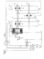
- Fig. 1 is an engine 12 of a motor vehicle in a schematic representation shown, which via the multi-plate clutch 1 torque to the gear transmission 9 can transmit.
- the internal combustion engine 12 by a first Connection member 5 connected to the outer plate carrier 3 of the multi-plate clutch 1.
- the outer plates 4 are arranged in a form-fitting manner in the outer plate carrier 3.
- the inner disk carrier 6 is over the connector 8 is firmly connected to the transmission input shaft 18.
- the foreign and inner slats 4, 7 are arranged alternately and can by means of of the piston 28 are compressed.
- the piston 28 we usually hydraulically operated, for which a pressure oil supply, not shown, is used.
- the plate pack can also be compressed electromechanically.
- the transmission output shaft is parallel to the transmission input shaft 18 21 arranged.
- a gear is designed as a ring gear, which can be positively connected to the shaft by means of the switching clutches 10 on which it sits.
- the clutches 10 of the automated shown Drive train are by means of gear actuators 24, which are not closer are shown, switched.
- the clutches 10 are axially open the transmission input shaft 18 or transmission output shaft 21 shifted.
- ECU 15 electronice control device 15 is provided.
- the control device 15 is connected via signal lines 23 the transmission actuators 24 as well as with the cooling oil supply and with the Shift lever 22 connected.
- the control unit can both signals such.
- B. Receive and process switching signals which are initiated by the shift lever 22, and control the transmission actuators by means of control signals. Usually switching signals can be initiated manually by the driver using the shift lever be, or in the case of an automatic driving mode, the switching signals automatically generated depending on driving parameters.
- the cooling oil supply consists essentially of an oil sump 26, from which means an oil pump 11 via an oil filter 25 by means of oil lines 27 cooling oil in the Multi-plate clutch can be promoted.
- 1 is an electric machine 13 as the drive of the oil pump 11.
- the oil pump can also be operated via gear wheels are powered by the vehicle engine.
- the oil pump 11, which is designed here as a controllable pump, is followed by a directional control valve 14.
- the directional control valve 14 is controlled by the control unit 15, and can be switched in two switch positions. In the first Switch position, the oil pump 11 via an oil line 27 with the multi-plate clutch 1 connected. In the second switching position, the oil pump 11 delivers the oil back into the oil sump 26.
- By switching the directional valve 14 can therefore Cooling oil flow through the multi-plate clutch 1 can be activated or blocked. However, in order to switch off the cooling oil flow through the multi-plate clutch 1 also possible to switch off the oil pump 11 directly by means of the control unit 15.
- control unit can both the electric machine 13 as well as the controllable pump 11 and the directional valve 14 can be influenced.
- Ways to switch off the cooling oil flow, in combination, are necessary to do this accomplish.
- the cooling oil passes through a rotary union, not shown here into the rotating multi-plate clutch 1 and flows through it from the radial inside radially outwards, with all friction surfaces by cleverly guiding the cooling oil 2 of the plate pack are flowed through.
- the multi-plate clutch is used for starting actuated by means of the clutch piston 28, the friction surfaces 2 the outer plates 4 and the inner plates 7 rub against each other and thus torque is transmitted to the gear transmission 9.
- the resulting friction in the form of heat is absorbed by the cooling oil flowing through, whereby this heats up.
- the heated cooling oil is returned to the oil sump 26 directed.
- Frictional power which has to be dissipated, arises as long as long the multi-plate clutch 1 is operated in slip; the outer slats 4, which turn at engine speed, thus have a different speed than the inner plates 7.
- a shift lever 22 is used to switch on Transfer switching signal to the control unit 15.
- the old gear is assigned by means of its associated clutch and the Gear actuator 24 designed.
- the clutches 10 shown here symbolically are conical trained and represent synchronizations, which are conical trained friction surfaces the speeds of the idler gear and the associated gear shaft synchronize. If the speed of the idler gear and the gear shaft are the same this is achieved by further shifting the clutch 10 axially positively connected to the gear shaft. Then the cooling oil flow activated again by the control unit 15 and the piston 28 is in Controlled in the direction of closing the multi-plate clutch 1.
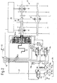
- FIG. 2 shows the drive train of a motor vehicle, which is an automated, powershiftable dual clutch transmission 17 and a multiple clutch device 16 has.
- the multiple clutch device 16 two multi-plate clutches nested radially one inside the other, each one Gearbox input shaft is assigned.
- the radially outer multi-plate clutch 1 connected to the inner transmission input shaft 18 and the inner Multi-plate clutch is with the outer transmission input shaft designed as a hollow shaft 19 connected.
- the gear ratios of the odd gears (1, 3, 5) are connected to the internal combustion engine 12 by means of the inner multi-plate clutch 1 connected.
- the straight ratio steps (2, 4, 6) are the radially outer multi-plate clutch 1 assigned.
- the cooling oil is by means of an oil pump 111a, which is driven by the internal combustion engine 12, from the oil sump 26, the filter 25, by means of a proportional directional valve 114 via a non- Rotary union between the multiple coupling device shown in detail 16 and the double clutch transmission 17 in the multiple clutch device 16 introduced radially inside.
- the proportional valve 114 is via a signal line 23 connected to the control unit 15 and is controlled by this. To the Cooling of the friction surfaces flows through the two from radially inside to radially outside Multi-plate clutches 1 in succession.
- the cooling oil is also targeted to the by means of suitable fluid guide arrangements can lead to cooling fins.
- the proportional valve 114 is switched so that the oil pump 1 1 1 a the oil essentially without pressure back into the oil sump 26 promotes.
- the multi-plate clutch which is assigned to the gear to be shifted is activated by controlling the corresponding proportional pressure control valve 116 opened, and the gear to be engaged by means of the associated Clutch 10 inserted by the gear actuator 24. Then will the cooling oil flow is switched on again by actuating valve 114 and one Overlap switching of the two multi-plate clutches 1 performed. in this connection the multi-plate clutch is activated by actuating the two pressure control valves 116 1 of the new gear closed and at the same time the multi-plate clutch of the old one Ganges open. Then the old gear can be laid out.
- the control device 15 controls 15 the directional control valve 114 according to the invention that the cooling oil flow to the Multi-plate clutch is passed.
- Malfunction of the actuator can e.g. B. can be detected via the pressure sensors 122. In this case, deliver the pressure sensors pressure values which are lower than those to be set Pressures in the piston chambers of the multi-plate clutch 1.
- the cause of such Malfunctions can e.g. B. a faulty connection of the control device 15 with the pressure control valves 26. Faulty control can also occur of the electric machine 13 or a complete incident of the same cause the malfunction.
- the drag torque of the cooling oil which is arranged on the transmission side Inner slats 7 acts, used.
- the proportional directional control valve 114 is according to the invention installed that it is switched in the currentless state so that it the cooling oil flow leads to the multiple clutch device 16. So even in the event of a total failure the electronic control unit 15, in which the directional control valve 114 can no longer be controlled, an emergency driving functionality ensured become.
- the combustion engine driven cooling oil pump 111 a promotes the cooling oil automatically goes to the plate packs.
- the drag torque is not only in the event of a malfunction of the actuator for torque transmission serves, but also in the presence of other operating parameters of the motor vehicle.
- the Motor vehicle serve the drag torque generated with the cooling oil, the pressure torque of the coupling device set by the actuating device to regulate more precisely.
- This is achieved according to the invention in that the Size of the cooling oil flow flowing through the fins 4.7 by means of the directional valve 114 is set.
Landscapes
- Engineering & Computer Science (AREA)
- General Engineering & Computer Science (AREA)
- Mechanical Engineering (AREA)
- Physics & Mathematics (AREA)
- Fluid Mechanics (AREA)
- Mechanical Operated Clutches (AREA)
- Hydraulic Clutches, Magnetic Clutches, Fluid Clutches, And Fluid Joints (AREA)
- Arrangement Of Transmissions (AREA)
Abstract
Description
Erfindungsgemäß ist dabei vorgesehen, dass der Kühlölstrom in Vorbereitung eines Schließens einer Schaltkupplung des Zahnradgetriebes abgeschaltet wird.
- Fig. 1
- Eine schematische Darstellung eines Antriebsstrangs eines Kraftfahrzeuges mit Lamellenkupplung und Zahnradgetriebe, eine zugehörige Kühlölversorgung und eine dazugehörige Steuereinheit;
- Fig. 2
- einen Antriebsstrang eines Kraftfahrzeuges mit einem Doppelkupplungsgetriebe und zugehöriger Mehrfachkupplungseinrichtung, sowie zugehöriger Ölversorgung.
- 1.
- Lamellenkupplung
- 2.
- Reibflächen
- 3.
- Außenlamellenträger
- 4.
- Außenlamelleh
- 5.
- Anschlussglied
- 6.
- Innenlamellenträger
- 7.
- Innenlamellen
- 8.
- Anschlussglied
- 9.
- Zahnradgetriebe
- 10.
- Schaltkupplungen
- 11.
- Ölpumpe
- 12.
- Verbrennungsmotor
- 13.
- Elektromaschine
- 14. Wegeventil 15.
- elektronische Steuereinheit
- 16.
- Mehrfach-Kupplungseinrichtung
- 17.
- Doppelkupplungsgetriebe
- 18.
- Getriebeeingangswelle
- 19.
- Hohlwelle
- 20.
- Übersetzungsstufen
- 21.
- Getriebeausgangswelle
- 22.
- Schalthebel
- 23.
- Signalleitung
- 24.
- Getriebeaktuator
- 25.
- Ölfilter
- 26.
- Ölsumpf
- 27.
- Ölleitung
- 28.
- Kolben
- 1 1 1 a.
- Kühlölpumpe
- 1 1 1 b.
- Druckölpumpe
- 114.
- proportionales Wegeventil
- 116
- proportionales Druckregelventil
- 118.
- Hydraulikspeicher
- 120.
- Rückschlagventil
- 122.
- Drucksensor
- 124.
- Druckkolben
Claims (18)
- Lamellenkupplung (1) mit, mit einem steuerbaren Kühlölstrom ölgekühlten Reibflächen (2), mit einem Außenlamellenträger (3) mit Außenlamellen (4) und einem ersten Anschlussglied (5) zur Drehmomentübertragung, mit einem Innenlamellenträger (6) mit Innenlamellen (7) und einem zweiten Anschlussglied (8) zur Drehmomentübertragung, für ein Zahnradgetriebe (9) mit einer Mehrzahl von formschlüssigen Schaltkupplungen (10) in einem Antriebsstrang eines Kraftfahrzeugs,
dadurch gekennzeichnet, dass der Kühlölstrom in Abhängigkeit von Betriebsparametern des Kraftfahrzeugs abgeschaltet oder zugeschaltet wird. - Lamellenkupplung (1) nach Anspruch 1,
dadurch gekennzeichnet, dass der Kühlölstrom in Vorbereitung eines Schließens einer Schaltkupplung (10) des Zahnradgetriebes (9) abgeschaltet wird. - Lamellenkupplung (1) nach Anspruch 1,
dadurch gekennzeichnet, dass der Kühlölstrom mittels einer Ölpumpe (11) bereitgestellt wird, welche durch den Verbrennungsmotor (12) des Kraftfahrzeugs oder durch eine separate Elektromaschine (13) angetrieben wird. - Lamellenkupplung (1) nach Anspruch 3,
dadurch gekennzeichnet, dass der Kühlölstrom durch die Lamellenkupplung (1) durch Abschalten des Ölpumpenantriebs oder/und durch Schalten eines Wegeventils (14) abgeschaltet wird. - Lamellenkupplung (1) nach Anspruch 1,
dadurch gekennzeichnet, dass der Kühlölstrom und die Betätigung der Schaltkupplungen( 10) von einer elektronischen Steuereinheit (15) gesteuert wird. - Lamellenkupplung (1) nach Anspruch 5,
dadurch gekennzeichnet, dass die Steuereinheit (15) Schaltsignale empfangen kann und daraufhin den Kühlölstrom durch die Lamellenkupplung (1) abschaltet. - Lamellenkupplung (1) nach Anspruch 2,
dadurch gekennzeichnet, dass nach dem Schließen einer Schaltkupplung (10) der Kühlölstrom durch die Lamellenkupplung (1) wieder angeschaltet wird. - Lamellenkupplung (1) nach Anspruch 1,
dadurch gekennzeichnet, dass die Lamellenkupplung (1) in einer Mehrfach-Kupplungseinrichtung (16) mit mindestens zwei Lamellenkupplungen (1) angeordnet ist, und dass das Zahnradgetriebe (9) als lastschaltbares Doppelkupplungsgetriebe (17) ausgebildet ist. - Lamellenkupplung (1) nach Anspruch 8,
dadurch gekennzeichnet, dass mindestens zwei Lamellenkupplungen (1) radial übereinander angeordnet sind und das der Kühlölstrom die Lamellenkupplungen (1) von radial innen nach radial außen durchströmt. - Lamellenkupplung (1) nach Anspruch 1,
dadurch gekennzeichnet, dass die Betriebsparameter des Kraftfahrzeugs Schaltvorgänge, Kuppelvorgänge, Anfahrvorgänge, Anrollvorgänge oder Kriechvorgänge sind. - Verfahren zum Betrieb eines zu einem Antriebsstrang eines Kraftfahrzeug gehörenden Antriebsstrangs, der aufweist:dadurch gekennzeichnet, dass der Kühlölstrom in Vorbereitung eines Schließens einer Schaltkupplung (10) des Zahnradgetriebes (9) abgeschaltet wird.eine Antriebseinheit (12), gegebenenfalls in Form eines Verbrennungsmotors (12), ein Zahnradgetriebe (9) mit einer Mehrzahl von formschlüssigen Schaltkupplungen (10) und mindestens eine, mit einem steuerbaren Kühlölstrom ölgekühlte Lamellenkupplung (1) mit einem Außenlamellenträger (3) mit Außenlamellen (4) und einem ersten Anschlussglied (5) zur Drehmomentübertragung und mit einem Innenlamellenträger (6) mit Innenlamellen (7) und einem zweiten Anschlussglied (8) zur Drehmomentübertragung
- Verfahren nach Anspruch 11,
dadurch gekennzeichnet, dass eine elektronische Steuereinheit (15) den Kühlölstrom entlang Reibflächen (2) der Lamellenkupplung (1) in Reaktion auf ein Schaltsignal abschaltet. - Verfahren nach Anspruch 12,
dadurch gekennzeichnet, dass die elektronische Steuereinheit (15) das Abschalten des Kühlölstroms und anschließend das Schließen der Schaltkupplung (10) bewirkt. - Lamellenkupplung (1) mit, mit einem steuerbaren Kühlölstrom ölgekühlten Reibflächen (2), mit einem Außenlamellenträger (3) mit Außenlamellen (4) und einem ersten Anschlussglied (5) zur Drehmomentübertragung, mit einem Innenlamellenträger (6) mit Innenlamellen (7) und einem zweiten Anschlussglied (8) zur Drehmomentübertragung, für ein Zahnradgetriebe (9) mit einer Mehrzahl von formschlüssigen Schaltkupplungen (10) in einem Antriebsstrang eines Kraftfahrzeugs,
dadurch gekennzeichnet, dass der Kühlölstrom zur Drehmomentübertragung zwischen Innenlamellen (7) und Außenlamellen (4) zugeschaltet wird oder zugeschaltet bleibt. - Lamellenkupplung (1) nach Anspruch 14,
dadurch gekennzeichnet, dass der Kühlölstrom bei beeinträchtigter Funktion einer Betätigungseinrichtung der Lamellenkupplung zur Drehmomentübertragung dient. - Lamellenkupplung (1) nach Anspruch 14,
dadurch gekennzeichnet, dass der Kühlölstrom beim Rangieren und/oder Kriechen zur Drehmomentübertragung dient. - Lamellenkupplung (1) nach Anspruch 14,
dadurch gekennzeichnet, dass der Kühlölstrom bei Ausfall einer Steuereinheit automatisch zugeschaltet wird. - Lamellenkupplung (1) nach Anspruch 15,
dadurch gekennzeichnet, dass bei einer Funktionsstörung der Betätigungseinrichtung der Lamellenkupplung in einen Notfahrbetrieb umgeschaltet wird, der Kühlölstrom zugeschaltet wird und/oder das maximale Motordrehmoment reduziert wird.
Priority Applications (2)
| Application Number | Priority Date | Filing Date | Title |
|---|---|---|---|
| EP03018439A EP1398520A3 (de) | 2002-09-12 | 2003-08-14 | Lamellenkupplung |
| DE10337556A DE10337556A1 (de) | 2002-09-12 | 2003-08-14 | Lamellenkupplung |
Applications Claiming Priority (2)
| Application Number | Priority Date | Filing Date | Title |
|---|---|---|---|
| DE10242288 | 2002-09-12 | ||
| DE10242288 | 2002-09-12 |
Publications (3)
| Publication Number | Publication Date |
|---|---|
| EP1398519A2 true EP1398519A2 (de) | 2004-03-17 |
| EP1398519A3 EP1398519A3 (de) | 2004-04-28 |
| EP1398519B1 EP1398519B1 (de) | 2005-10-26 |
Family
ID=31724676
Family Applications (1)
| Application Number | Title | Priority Date | Filing Date |
|---|---|---|---|
| EP02026125A Expired - Lifetime EP1398519B1 (de) | 2002-09-12 | 2002-11-23 | Lamellenkupplung |
Country Status (3)
| Country | Link |
|---|---|
| EP (1) | EP1398519B1 (de) |
| AT (1) | ATE307987T1 (de) |
| DE (1) | DE50204691D1 (de) |
Cited By (3)
| Publication number | Priority date | Publication date | Assignee | Title |
|---|---|---|---|---|
| EP2042766A3 (de) * | 2007-09-29 | 2009-04-22 | Honda Motor Co., Ltd. | Struktur zur Bereitstellung einer Kupplungssteuervorrichtung in einer Leistungseinheit für ein Motorrad |
| EP2068047A3 (de) * | 2007-12-05 | 2011-09-07 | Nissan Motor Co., Ltd. | Schaltsteuerungssystem |
| US8360218B2 (en) | 2007-09-29 | 2013-01-29 | Honda Motor Co., Ltd. | Structure for disposing clutch control apparatus in power unit for saddle-ride type vehicle |
Citations (7)
| Publication number | Priority date | Publication date | Assignee | Title |
|---|---|---|---|---|
| DE19800490A1 (de) | 1997-01-31 | 1998-08-20 | Audi Ag | Vorrichtung zur Kühlung zweier auf einer Getriebewelle angeordneter Lamellenkupplungen |
| DE19830951A1 (de) | 1998-07-10 | 2000-01-13 | Zahnradfabrik Friedrichshafen | Lamellenkupplung in einem leistungsverzweigten Getriebe |
| US6098771A (en) | 1999-05-03 | 2000-08-08 | Case Corporation | Clutch with on-demand cooling |
| EP1081401A2 (de) | 1999-08-24 | 2001-03-07 | BorgWarner Inc. | Lamellenreibkupplung mit Zwangsschmierung auf Anfrage |
| US6206163B1 (en) | 1999-11-13 | 2001-03-27 | Borgwarner Inc. | Flow control capsule for clutch lubrication and cooling |
| EP0822350B1 (de) | 1996-06-27 | 2001-10-24 | Toyota Jidosha Kabushiki Kaisha | Schmierung für eine Nasskupplung |
| DE10128856A1 (de) | 2000-11-17 | 2002-05-23 | Zf Sachs Ag | Kupplungssystem mit wenigstens einer Lamellen-Kupplungsanordnung, Antriebsstrang mit dem Kupplungssystem und Warmlaufverfahren hierfür |
Family Cites Families (3)
| Publication number | Priority date | Publication date | Assignee | Title |
|---|---|---|---|---|
| US4856628A (en) * | 1987-11-17 | 1989-08-15 | Hino Jidosha Kogyo Kabushiki Kaisha | Automated mechanical transmission system for use in commercial vehicles |
| US5988335A (en) * | 1998-06-02 | 1999-11-23 | Caterpillar Inc. | Control system for diverting oil from a clutch |
| DE10163404B4 (de) * | 2001-12-21 | 2009-06-04 | Zf Sachs Ag | Verfahren zur Steuerung eines Kupplungssystem mit wenigstens einer Lamellen-Kupplungsanordnung |
-
2002
- 2002-11-23 EP EP02026125A patent/EP1398519B1/de not_active Expired - Lifetime
- 2002-11-23 DE DE50204691T patent/DE50204691D1/de not_active Expired - Lifetime
- 2002-11-23 AT AT02026125T patent/ATE307987T1/de not_active IP Right Cessation
Patent Citations (7)
| Publication number | Priority date | Publication date | Assignee | Title |
|---|---|---|---|---|
| EP0822350B1 (de) | 1996-06-27 | 2001-10-24 | Toyota Jidosha Kabushiki Kaisha | Schmierung für eine Nasskupplung |
| DE19800490A1 (de) | 1997-01-31 | 1998-08-20 | Audi Ag | Vorrichtung zur Kühlung zweier auf einer Getriebewelle angeordneter Lamellenkupplungen |
| DE19830951A1 (de) | 1998-07-10 | 2000-01-13 | Zahnradfabrik Friedrichshafen | Lamellenkupplung in einem leistungsverzweigten Getriebe |
| US6098771A (en) | 1999-05-03 | 2000-08-08 | Case Corporation | Clutch with on-demand cooling |
| EP1081401A2 (de) | 1999-08-24 | 2001-03-07 | BorgWarner Inc. | Lamellenreibkupplung mit Zwangsschmierung auf Anfrage |
| US6206163B1 (en) | 1999-11-13 | 2001-03-27 | Borgwarner Inc. | Flow control capsule for clutch lubrication and cooling |
| DE10128856A1 (de) | 2000-11-17 | 2002-05-23 | Zf Sachs Ag | Kupplungssystem mit wenigstens einer Lamellen-Kupplungsanordnung, Antriebsstrang mit dem Kupplungssystem und Warmlaufverfahren hierfür |
Cited By (4)
| Publication number | Priority date | Publication date | Assignee | Title |
|---|---|---|---|---|
| EP2042766A3 (de) * | 2007-09-29 | 2009-04-22 | Honda Motor Co., Ltd. | Struktur zur Bereitstellung einer Kupplungssteuervorrichtung in einer Leistungseinheit für ein Motorrad |
| US8360218B2 (en) | 2007-09-29 | 2013-01-29 | Honda Motor Co., Ltd. | Structure for disposing clutch control apparatus in power unit for saddle-ride type vehicle |
| EP2068047A3 (de) * | 2007-12-05 | 2011-09-07 | Nissan Motor Co., Ltd. | Schaltsteuerungssystem |
| US8216110B2 (en) | 2007-12-05 | 2012-07-10 | Nissan Motor Co., Ltd. | Shifting control system |
Also Published As
| Publication number | Publication date |
|---|---|
| EP1398519B1 (de) | 2005-10-26 |
| DE50204691D1 (de) | 2005-12-01 |
| ATE307987T1 (de) | 2005-11-15 |
| EP1398519A3 (de) | 2004-04-28 |
Similar Documents
| Publication | Publication Date | Title |
|---|---|---|
| DE10163404B4 (de) | Verfahren zur Steuerung eines Kupplungssystem mit wenigstens einer Lamellen-Kupplungsanordnung | |
| EP1544513B1 (de) | Kraftfahrzeug mit einem eine Mehrfach-Kupplungseinrichtung aufweisenden Antriebsstrang | |
| EP2930388B1 (de) | Kupplungsanordnung und verfahren zu deren betätigung | |
| EP1482195B1 (de) | Kupplungsvorrichtung und Verfahren zum Betreiben einer Lamellenkupplung | |
| DE10230183B4 (de) | Verfahren zur Kühlfluidzuführung für Lamellenkupplungen und -bremsen in Automatgetrieben und Einrichtung zur Kühlfluidzuführung | |
| EP2769111B1 (de) | Vorrichtung zur steuerung eines kühl- und/oder schmierölstromes | |
| EP3921562B1 (de) | System zum betätigen einer parksperre | |
| DE10102029A1 (de) | Drehmomentübertragungsvorrichtung | |
| EP1990561B1 (de) | Verfahren zum Schalten eines Neutralzustandes eines automatisierten Stufengetriebes | |
| DE19826068C2 (de) | Betätigungsvorrichtung für ein Getriebe eines Kraftfahrzeuges | |
| DE60206852T2 (de) | Halbautomatisches Getriebe | |
| EP1644651A1 (de) | Automatikgetriebe mit einem hydraulisch betätigbaren schaltglied | |
| EP1398520A2 (de) | Lamellenkupplung | |
| DE10344106B4 (de) | Schaltstrategie und Getriebesteuerung für ein Getriebe, insbesondere für ein Doppelkupplungsgetriebe | |
| DE102011008250B4 (de) | System zum Steuern eines Getriebes | |
| EP2268933B1 (de) | Hydraulisch oder pneumatisch betätigbares formschlüssiges schaltelement | |
| DE10044493A1 (de) | Mehrfach-Kupplungseinrichtung, insbesondere Doppel-Kupplungseinrichtung, für lastschaltbare Getriebe | |
| DE102022130689B3 (de) | Vorrichtung und Verfahren zur Steuerung einer Kupplungseinrichtung | |
| EP1398519B1 (de) | Lamellenkupplung | |
| DE102014226517B4 (de) | Schalt- bzw. Anfahrelement | |
| DE202013002494U1 (de) | Automatgetriebe mit verrastbaren Schaltelementen | |
| WO2009065686A1 (de) | Lastschaltelement | |
| DE10337556A1 (de) | Lamellenkupplung | |
| DE102011100801B4 (de) | Kupplungsgetriebe mit einem Pumpen-Elektromotor, der mechanisch mit einem Ventil wirkverbunden ist, um das Ventil in Abhängigkeit der Drehrichtung des Elektromotors zu betätigen, Verfahren zum Betreiben dieses Kupplungsgetriebes | |
| DE102004060221B4 (de) | Getriebesteuervorrichtung zum Steuern mehrerer Drehmomentübertragungsmechanismen in einem Lastschaltgetriebe |
Legal Events
| Date | Code | Title | Description |
|---|---|---|---|
| PUAI | Public reference made under article 153(3) epc to a published international application that has entered the european phase |
Free format text: ORIGINAL CODE: 0009012 |
|
| PUAL | Search report despatched |
Free format text: ORIGINAL CODE: 0009013 |
|
| AK | Designated contracting states |
Kind code of ref document: A2 Designated state(s): AT BE BG CH CY CZ DE DK EE ES FI FR GB GR IE IT LI LU MC NL PT SE SK TR |
|
| AX | Request for extension of the european patent |
Extension state: AL LT LV MK RO SI |
|
| AK | Designated contracting states |
Kind code of ref document: A3 Designated state(s): AT BE BG CH CY CZ DE DK EE ES FI FR GB GR IE IT LI LU MC NL PT SE SK TR |
|
| AX | Request for extension of the european patent |
Extension state: AL LT LV MK RO SI |
|
| 17P | Request for examination filed |
Effective date: 20040408 |
|
| 17Q | First examination report despatched |
Effective date: 20040906 |
|
| AKX | Designation fees paid |
Designated state(s): AT BE BG CH CY CZ DE DK EE ES FI FR GB GR IE IT LI LU MC NL PT SE SK TR |
|
| GRAP | Despatch of communication of intention to grant a patent |
Free format text: ORIGINAL CODE: EPIDOSNIGR1 |
|
| GRAS | Grant fee paid |
Free format text: ORIGINAL CODE: EPIDOSNIGR3 |
|
| GRAA | (expected) grant |
Free format text: ORIGINAL CODE: 0009210 |
|
| AK | Designated contracting states |
Kind code of ref document: B1 Designated state(s): AT BE BG CH CY CZ DE DK EE ES FI FR GB GR IE IT LI LU MC NL PT SE SK TR |
|
| PG25 | Lapsed in a contracting state [announced via postgrant information from national office to epo] |
Ref country code: IT Free format text: LAPSE BECAUSE OF FAILURE TO SUBMIT A TRANSLATION OF THE DESCRIPTION OR TO PAY THE FEE WITHIN THE PRESCRIBED TIME-LIMIT;WARNING: LAPSES OF ITALIAN PATENTS WITH EFFECTIVE DATE BEFORE 2007 MAY HAVE OCCURRED AT ANY TIME BEFORE 2007. THE CORRECT EFFECTIVE DATE MAY BE DIFFERENT FROM THE ONE RECORDED. Effective date: 20051026 Ref country code: SK Free format text: LAPSE BECAUSE OF FAILURE TO SUBMIT A TRANSLATION OF THE DESCRIPTION OR TO PAY THE FEE WITHIN THE PRESCRIBED TIME-LIMIT Effective date: 20051026 Ref country code: CZ Free format text: LAPSE BECAUSE OF FAILURE TO SUBMIT A TRANSLATION OF THE DESCRIPTION OR TO PAY THE FEE WITHIN THE PRESCRIBED TIME-LIMIT Effective date: 20051026 Ref country code: TR Free format text: LAPSE BECAUSE OF FAILURE TO SUBMIT A TRANSLATION OF THE DESCRIPTION OR TO PAY THE FEE WITHIN THE PRESCRIBED TIME-LIMIT Effective date: 20051026 Ref country code: FI Free format text: LAPSE BECAUSE OF FAILURE TO SUBMIT A TRANSLATION OF THE DESCRIPTION OR TO PAY THE FEE WITHIN THE PRESCRIBED TIME-LIMIT Effective date: 20051026 Ref country code: NL Free format text: LAPSE BECAUSE OF FAILURE TO SUBMIT A TRANSLATION OF THE DESCRIPTION OR TO PAY THE FEE WITHIN THE PRESCRIBED TIME-LIMIT Effective date: 20051026 Ref country code: EE Free format text: LAPSE BECAUSE OF FAILURE TO SUBMIT A TRANSLATION OF THE DESCRIPTION OR TO PAY THE FEE WITHIN THE PRESCRIBED TIME-LIMIT Effective date: 20051026 Ref country code: IE Free format text: LAPSE BECAUSE OF FAILURE TO SUBMIT A TRANSLATION OF THE DESCRIPTION OR TO PAY THE FEE WITHIN THE PRESCRIBED TIME-LIMIT Effective date: 20051026 |
|
| REG | Reference to a national code |
Ref country code: GB Ref legal event code: FG4D Free format text: NOT ENGLISH |
|
| REG | Reference to a national code |
Ref country code: CH Ref legal event code: EP |
|
| PG25 | Lapsed in a contracting state [announced via postgrant information from national office to epo] |
Ref country code: CY Free format text: LAPSE BECAUSE OF FAILURE TO SUBMIT A TRANSLATION OF THE DESCRIPTION OR TO PAY THE FEE WITHIN THE PRESCRIBED TIME-LIMIT Effective date: 20051123 Ref country code: AT Free format text: LAPSE BECAUSE OF NON-PAYMENT OF DUE FEES Effective date: 20051123 |
|
| PG25 | Lapsed in a contracting state [announced via postgrant information from national office to epo] |
Ref country code: MC Free format text: LAPSE BECAUSE OF NON-PAYMENT OF DUE FEES Effective date: 20051130 Ref country code: BE Free format text: LAPSE BECAUSE OF NON-PAYMENT OF DUE FEES Effective date: 20051130 |
|
| REG | Reference to a national code |
Ref country code: IE Ref legal event code: FG4D Free format text: LANGUAGE OF EP DOCUMENT: GERMAN |
|
| REF | Corresponds to: |
Ref document number: 50204691 Country of ref document: DE Date of ref document: 20051201 Kind code of ref document: P |
|
| PG25 | Lapsed in a contracting state [announced via postgrant information from national office to epo] |
Ref country code: LU Free format text: LAPSE BECAUSE OF NON-PAYMENT OF DUE FEES Effective date: 20051226 |
|
| GBT | Gb: translation of ep patent filed (gb section 77(6)(a)/1977) |
Effective date: 20051214 |
|
| PG25 | Lapsed in a contracting state [announced via postgrant information from national office to epo] |
Ref country code: DK Free format text: LAPSE BECAUSE OF FAILURE TO SUBMIT A TRANSLATION OF THE DESCRIPTION OR TO PAY THE FEE WITHIN THE PRESCRIBED TIME-LIMIT Effective date: 20060126 Ref country code: SE Free format text: LAPSE BECAUSE OF FAILURE TO SUBMIT A TRANSLATION OF THE DESCRIPTION OR TO PAY THE FEE WITHIN THE PRESCRIBED TIME-LIMIT Effective date: 20060126 Ref country code: GR Free format text: LAPSE BECAUSE OF FAILURE TO SUBMIT A TRANSLATION OF THE DESCRIPTION OR TO PAY THE FEE WITHIN THE PRESCRIBED TIME-LIMIT Effective date: 20060126 Ref country code: BG Free format text: LAPSE BECAUSE OF FAILURE TO SUBMIT A TRANSLATION OF THE DESCRIPTION OR TO PAY THE FEE WITHIN THE PRESCRIBED TIME-LIMIT Effective date: 20060126 |
|
| PG25 | Lapsed in a contracting state [announced via postgrant information from national office to epo] |
Ref country code: ES Free format text: LAPSE BECAUSE OF FAILURE TO SUBMIT A TRANSLATION OF THE DESCRIPTION OR TO PAY THE FEE WITHIN THE PRESCRIBED TIME-LIMIT Effective date: 20060206 |
|
| PG25 | Lapsed in a contracting state [announced via postgrant information from national office to epo] |
Ref country code: PT Free format text: LAPSE BECAUSE OF FAILURE TO SUBMIT A TRANSLATION OF THE DESCRIPTION OR TO PAY THE FEE WITHIN THE PRESCRIBED TIME-LIMIT Effective date: 20060327 |
|
| NLV1 | Nl: lapsed or annulled due to failure to fulfill the requirements of art. 29p and 29m of the patents act | ||
| REG | Reference to a national code |
Ref country code: IE Ref legal event code: FD4D |
|
| ET | Fr: translation filed | ||
| PG25 | Lapsed in a contracting state [announced via postgrant information from national office to epo] |
Ref country code: FR Free format text: LAPSE BECAUSE OF NON-PAYMENT OF DUE FEES Effective date: 20060630 |
|
| PLBE | No opposition filed within time limit |
Free format text: ORIGINAL CODE: 0009261 |
|
| STAA | Information on the status of an ep patent application or granted ep patent |
Free format text: STATUS: NO OPPOSITION FILED WITHIN TIME LIMIT |
|
| 26N | No opposition filed |
Effective date: 20060727 |
|
| REG | Reference to a national code |
Ref country code: FR Ref legal event code: ST Effective date: 20060630 |
|
| PG25 | Lapsed in a contracting state [announced via postgrant information from national office to epo] |
Ref country code: LI Free format text: LAPSE BECAUSE OF NON-PAYMENT OF DUE FEES Effective date: 20061130 Ref country code: CH Free format text: LAPSE BECAUSE OF NON-PAYMENT OF DUE FEES Effective date: 20061130 |
|
| REG | Reference to a national code |
Ref country code: FR Ref legal event code: RN |
|
| REG | Reference to a national code |
Ref country code: CH Ref legal event code: PL |
|
| BERE | Be: lapsed |
Owner name: ZF SACHS A.G. Effective date: 20051130 |
|
| REG | Reference to a national code |
Ref country code: FR Ref legal event code: FC |
|
| PGRI | Patent reinstated in contracting state [announced from national office to epo] |
Ref country code: FR Effective date: 20080312 |
|
| PGRI | Patent reinstated in contracting state [announced from national office to epo] |
Ref country code: FR Effective date: 20080312 |
|
| PGFP | Annual fee paid to national office [announced via postgrant information from national office to epo] |
Ref country code: GB Payment date: 20091118 Year of fee payment: 8 |
|
| PGRI | Patent reinstated in contracting state [announced from national office to epo] |
Ref country code: FR Effective date: 20100503 |
|
| GBPC | Gb: european patent ceased through non-payment of renewal fee |
Effective date: 20101123 |
|
| PG25 | Lapsed in a contracting state [announced via postgrant information from national office to epo] |
Ref country code: GB Free format text: LAPSE BECAUSE OF NON-PAYMENT OF DUE FEES Effective date: 20101123 |
|
| PGFP | Annual fee paid to national office [announced via postgrant information from national office to epo] |
Ref country code: FR Payment date: 20121130 Year of fee payment: 11 |
|
| REG | Reference to a national code |
Ref country code: DE Ref legal event code: R081 Ref document number: 50204691 Country of ref document: DE Owner name: ZF FRIEDRICHSHAFEN AG, DE Free format text: FORMER OWNER: ZF SACHS AG, 97424 SCHWEINFURT, DE Effective date: 20130326 |
|
| REG | Reference to a national code |
Ref country code: FR Ref legal event code: ST Effective date: 20140731 |
|
| PG25 | Lapsed in a contracting state [announced via postgrant information from national office to epo] |
Ref country code: FR Free format text: LAPSE BECAUSE OF NON-PAYMENT OF DUE FEES Effective date: 20131202 |
|
| PGFP | Annual fee paid to national office [announced via postgrant information from national office to epo] |
Ref country code: DE Payment date: 20151118 Year of fee payment: 14 |
|
| REG | Reference to a national code |
Ref country code: DE Ref legal event code: R119 Ref document number: 50204691 Country of ref document: DE |
|
| PG25 | Lapsed in a contracting state [announced via postgrant information from national office to epo] |
Ref country code: DE Free format text: LAPSE BECAUSE OF NON-PAYMENT OF DUE FEES Effective date: 20170601 |