EP1398545A2 - Schaltvorrichtung für Wechselgetriebe mit kraftkompensierter Rückstellvorrichtung - Google Patents
Schaltvorrichtung für Wechselgetriebe mit kraftkompensierter Rückstellvorrichtung Download PDFInfo
- Publication number
- EP1398545A2 EP1398545A2 EP03292152A EP03292152A EP1398545A2 EP 1398545 A2 EP1398545 A2 EP 1398545A2 EP 03292152 A EP03292152 A EP 03292152A EP 03292152 A EP03292152 A EP 03292152A EP 1398545 A2 EP1398545 A2 EP 1398545A2
- Authority
- EP
- European Patent Office
- Prior art keywords
- rod
- cam
- neutral position
- selection
- control device
- Prior art date
- Legal status (The legal status is an assumption and is not a legal conclusion. Google has not performed a legal analysis and makes no representation as to the accuracy of the status listed.)
- Withdrawn
Links
Images



Classifications
-
- F—MECHANICAL ENGINEERING; LIGHTING; HEATING; WEAPONS; BLASTING
- F16—ENGINEERING ELEMENTS AND UNITS; GENERAL MEASURES FOR PRODUCING AND MAINTAINING EFFECTIVE FUNCTIONING OF MACHINES OR INSTALLATIONS; THERMAL INSULATION IN GENERAL
- F16H—GEARING
- F16H61/00—Control functions within control units of change-speed- or reversing-gearings for conveying rotary motion ; Control of exclusively fluid gearing, friction gearing, gearings with endless flexible members or other particular types of gearing
- F16H61/24—Providing feel, e.g. to enable selection
-
- F—MECHANICAL ENGINEERING; LIGHTING; HEATING; WEAPONS; BLASTING
- F16—ENGINEERING ELEMENTS AND UNITS; GENERAL MEASURES FOR PRODUCING AND MAINTAINING EFFECTIVE FUNCTIONING OF MACHINES OR INSTALLATIONS; THERMAL INSULATION IN GENERAL
- F16H—GEARING
- F16H63/00—Control outputs from the control unit to change-speed- or reversing-gearings for conveying rotary motion or to other devices than the final output mechanism
- F16H63/02—Final output mechanisms therefor; Actuating means for the final output mechanisms
- F16H63/30—Constructional features of the final output mechanisms
- F16H63/38—Detents
-
- F—MECHANICAL ENGINEERING; LIGHTING; HEATING; WEAPONS; BLASTING
- F16—ENGINEERING ELEMENTS AND UNITS; GENERAL MEASURES FOR PRODUCING AND MAINTAINING EFFECTIVE FUNCTIONING OF MACHINES OR INSTALLATIONS; THERMAL INSULATION IN GENERAL
- F16H—GEARING
- F16H59/00—Control inputs to control units of change-speed- or reversing-gearings for conveying rotary motion
- F16H59/02—Selector apparatus
- F16H2059/0295—Selector apparatus with mechanisms to return lever to neutral or datum position, e.g. by return springs
Definitions
- the present invention relates generally to the gearbox control for motor vehicles thermal, especially for motor vehicles.
- the invention relates to a gearbox control device of the type of those which include at least: a box; a rod of elongated selection along a longitudinal axis; a driving member, such as a gearshift finger, carried transversely by the selection rod; a plurality of driven organs controlled by the driving organ and each of which orders a fork from the box of speeds; and a recall mechanism comprising at least a first cam carried by said selection and at least a first ball linked to the housing and transmitting to the first cam a first elastic force, the first ball cooperating with the first cam to exert on said selection, as a function of an angular difference between the rotational position that this rod takes around the longitudinal axis and its neutral position, a couple elastic return which urges this rod towards its neutral position for any angular deviation at most equal to a first predetermined limit angle.
- the recall mechanism includes furthermore at least one second cam carried by said selection and at least a second ball linked to the case and transmitting a second force to the second cam elastic, selection rod in neutral position receiving balls, through the cams, a resulting force less than each of the first and second strength.
- the bowl of the first cam and the edge of the second cam are symmetrical with respect to a median plane and elongated along the longitudinal axis and the first and second balls are respectively mounted mobile, in parallel to the transverse axis, in first and second sockets attached to the housing, the device comprising first and second springs respectively arranged in the first and second sockets and requesting the first and second balls to the first and second respective cam.
- the object of the present invention is to propose a box control device for speeds to overcome at least one of disadvantages above.
- the gearbox control device speeds according to the invention is essentially characterized in that in the recall mechanism that includes at least a second cam carried by the selection rod and at least one second ball linked to the housing and transmitting to the second cam, a second elastic force, means are provided so that said selection in neutral position receives balls, via cams, a result force always strictly nothing.
- the elastic force exerted by the first ball on the stem is completely counterbalanced by the elastic force exerted by the second ball, this characteristic having the effect of both reduce the stress on the rod selection against its bearings, and allow a reduction of the stress of each ball on the cam corresponding, insofar as two elastic forces are used to define the neutral position of the rod of selection, and where each of them can therefore be more weak than the unique elastic force used previously in an embodiment where the mechanism of booster includes a single cam carried by the selection and a single ball transmitting to the cam a elastic force.
- the first ball exerts an elastic torque on the selection rod of rotation about an axis transverse to the axis longitudinal, the first and second balls being respectively mounted mobile, parallel to the axis transverse, in first and second sockets sliding mounted in the housing.
- the means of solicitation include a single spring, the ends of which respective relate to the first and second sockets and stress the first and second balls to the respective first and second cams in producing a strictly zero resultant force on the gear selection rod in neutral position.
- the first and second balls are for example diametrically opposed to each other with respect to the transverse axis.
- the first and second elastic forces can then be antagonistic and directed towards the axis transverse for the neutral position of the selection, these forces then compensating each other by strictly because they have exactly the same module for the neutral position of the selector rod.
- each first and second cams, or one of them at less includes symmetrical ramps with respect to a median plane passing through the transverse axis and parallel to the longitudinal axis.
- the first ball cooperates preferably with the first cam to exercise on the rod selection, depending on the angular difference between the position of rotation adopted by this rod around the axis longitudinal and neutral position, elastic torque of engagement which moves this rod from its neutral position and requests it towards one of its active positions of rotation for any angular deviation at least equal, in absolute value, at the first limit angle determined.
- the first and second cams may be different one the other.
- the second ball can cooperate with the second cam to exert on the rod selection, depending on the angular difference between the position of rotation adopted by this rod around the axis longitudinal and neutral position, elastic torque of engagement which moves this rod from its neutral position and requests it towards one of its active positions of rotation for any angular deviation at least equal, in absolute value, at a second determined limit angle, less than the first limit angle determined.
- the first cam provides a bowl for the first ball and the second cam an edge at the second ball.
- the second ball can thus leave the edge of the second cam for a rotation of small amplitude of the selection rod since its neutral position, and where the force then exerted by the second ball on the second cam generates on the rod a engagement couple that opposes the recall couple that generates the contact force exerted by the first ball on the bowl of the first cam, the torque resulting exerted on the rod becomes a couple of engagement for a rotation of the amplitude rod much lower than in known devices.
- the bowl of the first cam and the edge of the second cam, or at least one of them is symmetrical with respect to the median plane and elongated parallel to the transverse axis.
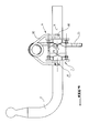
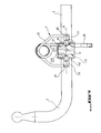
- the invention relates to a gearbox control device comprising essentially a housing 1, a selection rod 2, a shifting finger 20 forming a driving member and carried transversely by the selection rod 2, a set of driven organs (not shown but of a type known for example by the French patent application Applicant's No. 0 111 868, published March 14, 2003 under No. 2 829 549) and a recall mechanism 4.
- Selection rod 2 is elongated along an axis longitudinal X and mounted mobile in rotation around the longitudinal axis X and in translation along this axis, for example by means of bearings integral with the box 1 and not shown.
- each of the driven organs can be controlled by the passage finger 20 of rod 2, and order tower, through the bar that carries it, a corresponding range of the gearbox.
- the conducted organs may adopt a rest position in which they are aligned according to the longitudinal axis X and that each of its organs can also, by translation along the transverse axis Y, adopt two active translation positions arranged symmetrically on either side of its position of rest.
- the selection rod 2 initially placed in its angularly neutral position, is driven in rotation by the driver of the vehicle, in one way or the other, to adopt one or the other of its two active positions of rotation arranged symmetrically on either side of the neutral position, and to allow corresponding passage finger 20 to go from its rest position to its first position active or at its second active position.
- the mechanism of reminder 4 includes a first cam 51 which is carried by said selection 2, and a first ball 61 and, likewise, a second cam 52, also carried by said selection 2, and a second ball 62.
- the balls 61, 62 are mounted mobile, parallel to the longitudinal axis, respectively in a socket 71, 72 sliding mounted in the case 1 and on which the ends act 80, 81 of a spring 82 prestressed in compression.
- the spring 82 biases resiliently the socket 71, so that the ball 61 leans on cam 51 and transmits a force to it elastic F1 (figure 4).
- the cam 51 comprises two ramps 501 elongated in the direction of a Y axis transverse to the longitudinal X axis and they are symmetrical to each other with respect to a median plane which passes through the transverse axis Y and which is parallel to the longitudinal axis X.
- the ramps 501 frame a bowl 510, which also belongs to cam 51, which is symmetrical by in relation to the median plane, which is also elongated in the direction of the transverse axis Y.
- the ball 61 therefore rests on the bottom of the bowl 510 in the neutral position of the selection rod 2, while it rests on one or the other of the ramps 501 when the selector rod moves towards one or the other of its active positions (see Figure 5).
- the ball 61 thus exerts on the rod 2, by through cam 51, an elastic torque of rotation about the transverse axis Y whose modulus and the direction depend on the spring preload 82 and the angle formed by the point of tangency of the ball 61 and of cam 51, normal to the surface of cam 51 by relation to the median plane.
- the ball 61 cooperates with one or the other of the ramps 501 of the cam 51 to exert a torque on the selection rod 2 elastic engagement which moves this rod 2 away from its neutral position and requests it towards one or the other of its active positions.
- the spring 82 urges resiliently the socket 71, so that the ball 61 leans on cam 52 and transmits a force to it elastic F2 (figure 4).
- the balls 61 and 62 are diametrically opposite one to the other with respect to the transverse axis Y, and the forces elastics F1 and F2 are antagonistic, directed towards the transverse axis and, due to the action of the spring 82, have exactly the same module for the neutral position of the selection rod 2.
- a total compensation of the forces elastics applied to rod 2 could be obtained with a number of cams and balls other than two, for example with three cams, arranged at 120 ° one of the other around the transverse axis Y, and three balls corresponding.
- the cam 52 comprises two ramps 502, elongated in the direction of the transverse axis Y, and symmetrical one on the other with respect to a median plane which passes through the transverse axis Y and which is parallel to the axis longitudinal X.
- the cams 51 and 52 are different from each other.
- the ramps 502 form the sides an edge 520, which also belongs to the cam 52, which is symmetrical with respect to the median plane, and which is also lying in the direction of the axis transverse Y.
- the ball 62 is in support and in metastable equilibrium on edge 520 in the neutral position of the rod selection 2, and pressing without balance on the ramps 502 as soon as the selection rod 2 has moved away angularly from its neutral position by at least one angle equal to a limit angle, itself significantly less than the limit angle mentioned above which must rotate selection rod 2 to allow the ball 61 to exit the bowl 510.
- the ball 62 cooperates with cam 52 for exerting a torque on this rod elastic engagement which moves it away from its position neutral and which requests it towards one of its positions rotation assets.
- the resulting torque applied to the rod by the combined action of the balls 61 and 62 on cams 51 and 52 becomes a engagement torque for a relatively small angle of rotation of the rod selection 2 with respect to its neutral position.
Landscapes
- Engineering & Computer Science (AREA)
- General Engineering & Computer Science (AREA)
- Mechanical Engineering (AREA)
- Gear-Shifting Mechanisms (AREA)
Applications Claiming Priority (2)
| Application Number | Priority Date | Filing Date | Title |
|---|---|---|---|
| FR0211386 | 2002-09-13 | ||
| FR0211386A FR2844568B1 (fr) | 2002-09-13 | 2002-09-13 | Dispositif de commande de boites de vitesses a couple de rappel compense |
Publications (2)
| Publication Number | Publication Date |
|---|---|
| EP1398545A2 true EP1398545A2 (de) | 2004-03-17 |
| EP1398545A3 EP1398545A3 (de) | 2009-12-30 |
Family
ID=31726053
Family Applications (1)
| Application Number | Title | Priority Date | Filing Date |
|---|---|---|---|
| EP03292152A Withdrawn EP1398545A3 (de) | 2002-09-13 | 2003-09-02 | Schaltvorrichtung für Wechselgetriebe mit kraftkompensierter Rückstellvorrichtung |
Country Status (2)
| Country | Link |
|---|---|
| EP (1) | EP1398545A3 (de) |
| FR (1) | FR2844568B1 (de) |
Cited By (1)
| Publication number | Priority date | Publication date | Assignee | Title |
|---|---|---|---|---|
| EP3396214A1 (de) * | 2017-04-27 | 2018-10-31 | DURA Automotive Holdings U.K., Ltd. | Schaltfinger mit doppelter kugelverriegelung |
Citations (1)
| Publication number | Priority date | Publication date | Assignee | Title |
|---|---|---|---|---|
| FR2829549A1 (fr) | 2001-09-13 | 2003-03-14 | Peugeot Citroen Automobiles Sa | Dispositif de commande de vitesses a couple de rappel partage |
Family Cites Families (3)
| Publication number | Priority date | Publication date | Assignee | Title |
|---|---|---|---|---|
| JPS5861950U (ja) * | 1981-10-20 | 1983-04-26 | トヨタ自動車株式会社 | 手動変速機のシフト機構 |
| DE19741633C1 (de) * | 1997-09-20 | 1999-03-25 | Ford Global Tech Inc | Schaltvorrichtung für ein Wechselgetriebe von Kraftfahrzeugen |
| DE19911662A1 (de) * | 1999-03-16 | 2000-09-21 | Volkswagen Ag | Rastvorrichtung |
-
2002
- 2002-09-13 FR FR0211386A patent/FR2844568B1/fr not_active Expired - Fee Related
-
2003
- 2003-09-02 EP EP03292152A patent/EP1398545A3/de not_active Withdrawn
Patent Citations (1)
| Publication number | Priority date | Publication date | Assignee | Title |
|---|---|---|---|---|
| FR2829549A1 (fr) | 2001-09-13 | 2003-03-14 | Peugeot Citroen Automobiles Sa | Dispositif de commande de vitesses a couple de rappel partage |
Cited By (1)
| Publication number | Priority date | Publication date | Assignee | Title |
|---|---|---|---|---|
| EP3396214A1 (de) * | 2017-04-27 | 2018-10-31 | DURA Automotive Holdings U.K., Ltd. | Schaltfinger mit doppelter kugelverriegelung |
Also Published As
| Publication number | Publication date |
|---|---|
| FR2844568B1 (fr) | 2005-11-11 |
| FR2844568A1 (fr) | 2004-03-19 |
| EP1398545A3 (de) | 2009-12-30 |
Similar Documents
| Publication | Publication Date | Title |
|---|---|---|
| FR2607050A1 (fr) | Outil a moteur a deux vitesses dont le passage d'une vitesse a l'autre est effectue automatiquement par un dispositif a came, tel que perceuses ou analogues | |
| FR3005295A1 (fr) | Systeme de freins a servofrein electrique | |
| FR2917362A1 (fr) | Dispositif de serrage electrique d'une colonne de direction reglable de vehicule automobile | |
| FR2798177A1 (fr) | Boite de vitesses a clavetage | |
| FR2479939A1 (fr) | Engrenages planetaires du type a rouleaux ayant un agencement de prechargement | |
| FR2546454A1 (fr) | Vehicule de travail autopropulse | |
| CA1063388A (fr) | Dispositifs de transmission de vitesse | |
| FR2844568A1 (fr) | Dispositif de commande de boites de vitesses a couple de rappel compense | |
| FR2829549A1 (fr) | Dispositif de commande de vitesses a couple de rappel partage | |
| EP0299859B1 (de) | Hintenlenk-Steuervorrichtung für Fahrzeuge mit Vierradlenkung | |
| FR2917797A1 (fr) | Transmission entre un organe moteur et des roues et engin comportant une telle transmission | |
| EP1911992B1 (de) | Vorrichtung zur Übertragung von Bewegungen sowie entsprechende elektrische Ausstattung und entsprechendes Kraftfahrzeug | |
| EP0627053B1 (de) | Mechanismus zur stufenlosen veränderung einer drehgeschwindigkeit zwischen einem antrieb und einem abtrieb | |
| FR2902073A1 (fr) | Dispositif de transmission a changement de vitesse automatique pour bicyclette | |
| FR2525783A1 (fr) | Ensemble de support de changement de vitesses | |
| FR2806118A1 (fr) | Actionneur de serrure d'ouvrant de vehicule a limiteur de couple integre | |
| FR2884888A1 (fr) | Dispositif de commande de boite de vitesses pour vehicule automobile | |
| EP1437633A1 (de) | Räderwerk eines Chronographes | |
| EP0615501B1 (de) | Hilfskraftlenkung mit automatischem spielausgleich | |
| FR2864599A1 (fr) | Dispositif de serrage et de desserrage d'un frein de parking motorise | |
| FR3166609A1 (fr) | Systéme de transmission variable pour cycle et cycle a pédales associé | |
| FR3156423A1 (fr) | Module mécatronique d’assistance électrique | |
| FR2827250A1 (fr) | Systeme de direction pour vehicule automobile | |
| FR3115499A1 (fr) | Véhicule comprenant un dispositif de blocage d’un mécanisme d’inclinaison | |
| FR3149660A1 (fr) | Dispositif de blocage d'une transmission de chaîne cinématique dans un véhicule automobile |
Legal Events
| Date | Code | Title | Description |
|---|---|---|---|
| PUAI | Public reference made under article 153(3) epc to a published international application that has entered the european phase |
Free format text: ORIGINAL CODE: 0009012 |
|
| AK | Designated contracting states |
Kind code of ref document: A2 Designated state(s): AT BE BG CH CY CZ DE DK EE ES FI FR GB GR HU IE IT LI LU MC NL PT RO SE SI SK TR |
|
| AX | Request for extension of the european patent |
Extension state: AL LT LV MK |
|
| PUAL | Search report despatched |
Free format text: ORIGINAL CODE: 0009013 |
|
| AK | Designated contracting states |
Kind code of ref document: A3 Designated state(s): AT BE BG CH CY CZ DE DK EE ES FI FR GB GR HU IE IT LI LU MC NL PT RO SE SI SK TR |
|
| AX | Request for extension of the european patent |
Extension state: AL LT LV MK |
|
| STAA | Information on the status of an ep patent application or granted ep patent |
Free format text: STATUS: THE APPLICATION IS DEEMED TO BE WITHDRAWN |
|
| AKY | No designation fees paid | ||
| 18D | Application deemed to be withdrawn |
Effective date: 20100401 |
|
| REG | Reference to a national code |
Ref country code: DE Ref legal event code: 8566 |