EP1398602A2 - Positionsmess- und Steuervorrichtung für Hebebühnen - Google Patents
Positionsmess- und Steuervorrichtung für Hebebühnen Download PDFInfo
- Publication number
- EP1398602A2 EP1398602A2 EP03019591A EP03019591A EP1398602A2 EP 1398602 A2 EP1398602 A2 EP 1398602A2 EP 03019591 A EP03019591 A EP 03019591A EP 03019591 A EP03019591 A EP 03019591A EP 1398602 A2 EP1398602 A2 EP 1398602A2
- Authority
- EP
- European Patent Office
- Prior art keywords
- signal
- sensor
- detected
- measuring device
- hydraulic
- Prior art date
- Legal status (The legal status is an assumption and is not a legal conclusion. Google has not performed a legal analysis and makes no representation as to the accuracy of the status listed.)
- Withdrawn
Links
- 238000011156 evaluation Methods 0.000 claims abstract description 35
- 238000000034 method Methods 0.000 claims abstract description 22
- 238000012937 correction Methods 0.000 claims description 28
- 239000012530 fluid Substances 0.000 claims description 10
- 230000003287 optical effect Effects 0.000 claims description 8
- 238000012545 processing Methods 0.000 claims description 6
- 230000004888 barrier function Effects 0.000 claims description 4
- 230000011514 reflex Effects 0.000 claims description 4
- 230000008569 process Effects 0.000 claims description 3
- 238000001914 filtration Methods 0.000 claims description 2
- 238000005259 measurement Methods 0.000 abstract description 15
- 238000001514 detection method Methods 0.000 description 26
- 230000001276 controlling effect Effects 0.000 description 6
- 230000001360 synchronised effect Effects 0.000 description 6
- 238000011109 contamination Methods 0.000 description 4
- 230000033228 biological regulation Effects 0.000 description 3
- 230000008859 change Effects 0.000 description 3
- 230000006735 deficit Effects 0.000 description 3
- 238000010586 diagram Methods 0.000 description 3
- 238000006073 displacement reaction Methods 0.000 description 3
- 238000010147 laser engraving Methods 0.000 description 3
- 239000000463 material Substances 0.000 description 3
- 230000008901 benefit Effects 0.000 description 2
- 238000010276 construction Methods 0.000 description 2
- 230000001419 dependent effect Effects 0.000 description 2
- 239000010720 hydraulic oil Substances 0.000 description 2
- 238000012886 linear function Methods 0.000 description 2
- 238000012423 maintenance Methods 0.000 description 2
- 239000003550 marker Substances 0.000 description 2
- 239000003921 oil Substances 0.000 description 2
- 230000005855 radiation Effects 0.000 description 2
- 230000035945 sensitivity Effects 0.000 description 2
- 230000009466 transformation Effects 0.000 description 2
- OKTJSMMVPCPJKN-UHFFFAOYSA-N Carbon Chemical compound [C] OKTJSMMVPCPJKN-UHFFFAOYSA-N 0.000 description 1
- XUIMIQQOPSSXEZ-UHFFFAOYSA-N Silicon Chemical compound [Si] XUIMIQQOPSSXEZ-UHFFFAOYSA-N 0.000 description 1
- 238000005299 abrasion Methods 0.000 description 1
- 238000006243 chemical reaction Methods 0.000 description 1
- 230000007423 decrease Effects 0.000 description 1
- 238000013461 design Methods 0.000 description 1
- 238000011161 development Methods 0.000 description 1
- 230000018109 developmental process Effects 0.000 description 1
- 230000000694 effects Effects 0.000 description 1
- 230000002452 interceptive effect Effects 0.000 description 1
- 238000011089 mechanical engineering Methods 0.000 description 1
- 238000003801 milling Methods 0.000 description 1
- 230000010355 oscillation Effects 0.000 description 1
- 230000000737 periodic effect Effects 0.000 description 1
- 230000010363 phase shift Effects 0.000 description 1
- 230000001105 regulatory effect Effects 0.000 description 1
- 229910052710 silicon Inorganic materials 0.000 description 1
- 239000010703 silicon Substances 0.000 description 1
- 238000001228 spectrum Methods 0.000 description 1
- 238000011144 upstream manufacturing Methods 0.000 description 1
Images


Classifications
-
- G—PHYSICS
- G01—MEASURING; TESTING
- G01D—MEASURING NOT SPECIALLY ADAPTED FOR A SPECIFIC VARIABLE; ARRANGEMENTS FOR MEASURING TWO OR MORE VARIABLES NOT COVERED IN A SINGLE OTHER SUBCLASS; TARIFF METERING APPARATUS; MEASURING OR TESTING NOT OTHERWISE PROVIDED FOR
- G01D5/00—Mechanical means for transferring the output of a sensing member; Means for converting the output of a sensing member to another variable where the form or nature of the sensing member does not constrain the means for converting; Transducers not specially adapted for a specific variable
- G01D5/26—Mechanical means for transferring the output of a sensing member; Means for converting the output of a sensing member to another variable where the form or nature of the sensing member does not constrain the means for converting; Transducers not specially adapted for a specific variable characterised by optical transfer means, i.e. using infrared, visible, or ultraviolet light
- G01D5/32—Mechanical means for transferring the output of a sensing member; Means for converting the output of a sensing member to another variable where the form or nature of the sensing member does not constrain the means for converting; Transducers not specially adapted for a specific variable characterised by optical transfer means, i.e. using infrared, visible, or ultraviolet light with attenuation or whole or partial obturation of beams of light
- G01D5/34—Mechanical means for transferring the output of a sensing member; Means for converting the output of a sensing member to another variable where the form or nature of the sensing member does not constrain the means for converting; Transducers not specially adapted for a specific variable characterised by optical transfer means, i.e. using infrared, visible, or ultraviolet light with attenuation or whole or partial obturation of beams of light the beams of light being detected by photocells
- G01D5/347—Mechanical means for transferring the output of a sensing member; Means for converting the output of a sensing member to another variable where the form or nature of the sensing member does not constrain the means for converting; Transducers not specially adapted for a specific variable characterised by optical transfer means, i.e. using infrared, visible, or ultraviolet light with attenuation or whole or partial obturation of beams of light the beams of light being detected by photocells using displacement encoding scales
- G01D5/34746—Linear encoders
-
- B—PERFORMING OPERATIONS; TRANSPORTING
- B66—HOISTING; LIFTING; HAULING
- B66F—HOISTING, LIFTING, HAULING OR PUSHING, NOT OTHERWISE PROVIDED FOR, e.g. DEVICES WHICH APPLY A LIFTING OR PUSHING FORCE DIRECTLY TO THE SURFACE OF A LOAD
- B66F7/00—Lifting frames, e.g. for lifting vehicles; Platform lifts
- B66F7/28—Constructional details, e.g. end stops, pivoting supporting members, sliding runners adjustable to load dimensions
-
- F—MECHANICAL ENGINEERING; LIGHTING; HEATING; WEAPONS; BLASTING
- F15—FLUID-PRESSURE ACTUATORS; HYDRAULICS OR PNEUMATICS IN GENERAL
- F15B—SYSTEMS ACTING BY MEANS OF FLUIDS IN GENERAL; FLUID-PRESSURE ACTUATORS, e.g. SERVOMOTORS; DETAILS OF FLUID-PRESSURE SYSTEMS, NOT OTHERWISE PROVIDED FOR
- F15B11/00—Servomotor systems without provision for follow-up action; Circuits therefor
- F15B11/16—Servomotor systems without provision for follow-up action; Circuits therefor with two or more servomotors
- F15B11/22—Synchronisation of the movement of two or more servomotors
-
- F—MECHANICAL ENGINEERING; LIGHTING; HEATING; WEAPONS; BLASTING
- F15—FLUID-PRESSURE ACTUATORS; HYDRAULICS OR PNEUMATICS IN GENERAL
- F15B—SYSTEMS ACTING BY MEANS OF FLUIDS IN GENERAL; FLUID-PRESSURE ACTUATORS, e.g. SERVOMOTORS; DETAILS OF FLUID-PRESSURE SYSTEMS, NOT OTHERWISE PROVIDED FOR
- F15B15/00—Fluid-actuated devices for displacing a member from one position to another; Gearing associated therewith
- F15B15/20—Other details, e.g. assembly with regulating devices
- F15B15/28—Means for indicating the position, e.g. end of stroke
- F15B15/2815—Position sensing, i.e. means for continuous measurement of position, e.g. LVDT
- F15B15/2846—Position sensing, i.e. means for continuous measurement of position, e.g. LVDT using detection of markings, e.g. markings on the piston rod
-
- G—PHYSICS
- G01—MEASURING; TESTING
- G01D—MEASURING NOT SPECIALLY ADAPTED FOR A SPECIFIC VARIABLE; ARRANGEMENTS FOR MEASURING TWO OR MORE VARIABLES NOT COVERED IN A SINGLE OTHER SUBCLASS; TARIFF METERING APPARATUS; MEASURING OR TESTING NOT OTHERWISE PROVIDED FOR
- G01D5/00—Mechanical means for transferring the output of a sensing member; Means for converting the output of a sensing member to another variable where the form or nature of the sensing member does not constrain the means for converting; Transducers not specially adapted for a specific variable
- G01D5/26—Mechanical means for transferring the output of a sensing member; Means for converting the output of a sensing member to another variable where the form or nature of the sensing member does not constrain the means for converting; Transducers not specially adapted for a specific variable characterised by optical transfer means, i.e. using infrared, visible, or ultraviolet light
- G01D5/32—Mechanical means for transferring the output of a sensing member; Means for converting the output of a sensing member to another variable where the form or nature of the sensing member does not constrain the means for converting; Transducers not specially adapted for a specific variable characterised by optical transfer means, i.e. using infrared, visible, or ultraviolet light with attenuation or whole or partial obturation of beams of light
- G01D5/34—Mechanical means for transferring the output of a sensing member; Means for converting the output of a sensing member to another variable where the form or nature of the sensing member does not constrain the means for converting; Transducers not specially adapted for a specific variable characterised by optical transfer means, i.e. using infrared, visible, or ultraviolet light with attenuation or whole or partial obturation of beams of light the beams of light being detected by photocells
- G01D5/36—Forming the light into pulses
- G01D5/363—Direction discrimination
Definitions
- the invention relates to a method and a device for determining the position of a movable body, in particular a piston rod a hydraulic cylinder, and a control device for Hydraulic cylinder.
- Lifts especially for vehicles, usually have one or several lifting units for lifting or lowering a platform, on which the object to be lifted stands.
- a to be raised Vehicle is, for example, on one or more parts Platform (driving surface) raised to work on the vehicle is lifted by the lifting unit (s).
- the vehicle can also be of a structure with one or more arms be raised.
- DE 100 14 194 discloses a device for determining the Position of a piston rod at the markings in the form of a bar code are applied to the piston rod.
- An optical sensor detects the markings and an evaluation unit determines the (absolute) Position of the piston rod based on the bar code read. There several markings must be read for each bar code, this absolute path measurement has a low accuracy.
- EP 0 866 306 describes a device for distance measurement, where a friction wheel rolls on a cylinder piston rod. at this non-positive displacement measurement can occur if it is dirty slip problems occur, especially on one smooth, oily cylinder rod of a lifting cylinder.
- DE 35 15 762 is for hydraulic hoists with two lifting cylinders a so-called encoder / slave system for synchronous control the lifting cylinder is known.
- the two connected Lift cylinders are designed so that the volume in the rod space of the one cylinder the volume of the piston chamber in the second cylinder equivalent. With this arrangement, the movements of the piston rod hydraulically synchronized. An independent process however, the piston rods of the two cylinders are no longer possible.
- the object of the present invention is a method and a Device for accurately determining the position of a movable Body, in particular a piston rod of a hydraulic cylinder, and a control device for robust and precise control to create the travel of hydraulic cylinders.
- the measuring device for determining the position x of a movable body with several waymarks has a sensor on the one at least one waypoint and / or at least one Space between the waypoints encompassing area of the body. All types of markings are used as waymarks suitable on the body, which can be detected by the sensor. Suitable markings are, for example, optical or magnetic Marks.
- the sensor detects the presence of one or more of the waymarks in the area detected by the sensor of the body.
- the sensor signal provides a value for the share in the sensor detection area, that of one or more waymarks is taken. Conversely, one can also from the sensor signal Value for the proportion of spaces between the waypoints or the parts of the body not covered by markings is taken, determined.
- the type of sensor used suitably corresponds to the type of marking used, for example optically or magnetically. In principle, everyone is Sensors possible, the proportion of the markings on the sensor can determine the detected area.
- Such sensors can be different Material properties of waypoints and spaces evaluate to the share of the waymarks in the detected area of the body.
- An evaluation device determines the position x of the movable one Body based on the output signal S of the sensor. To move of the body by a multiple of the distance between the To detect waypoints, the evaluation device can read a counter Z taking into account the maxima and / or minima of the Change sensor output signal S (incremental displacement measurement).
- maxima or minima of the sensor signal occur S on.
- the proportion of the marking in the area detected by the sensor becomes maximum or minimum. For example, a minimum of Sensor signal S are present when the area covered by the sensor is complete is covered by a waymark. However, there is no milestone in the area detected by the sensor, a maximum of Sensor signal S are present.
- the distance d between the waypoints does not correspond to the dimension a of the waymarks in the direction of movement of the body are maxima and evaluate minima separately, count and with the corresponding Dimensions of waypoints and spaces charge.
- the evaluation device can determine the relationship between the area Aw of the waypoint detected by the sensor and the area Az of the intermediate space detected by the sensor on the basis of the signal value of the sensor output signal S. Since the sensor signal S is influenced by the (material) differences of the waymark and the space, the respective proportion of the marking and space in the area detected by the sensor can be determined on the basis of the signal value of the signal S. With a suitable coordination of markings and sensor, the relationship between the signal value of the sensor output signal S and the proportion of the areas A W , A Z detected by the sensor follows a known function.
- the area of a rectangular marking detected by a sensor with a rectangular detection area increases linearly with the movement of the body in a straight line until the maximum possible area of the marking is detected by the sensor. With a further displacement of the body, the area of the marking detected by the sensor in turn decreases linearly with the distance covered.
- x 1 indicates the approximate position in multiples of the way mark distance d and x 2 a correction value relative to one of the way points.
- This combined incremental / absolute path measurement enables the position of the movable body to be determined with great accuracy.
- the maximum possible path resolution is limited by the resolution of the sensor and the accuracy of the evaluation device.
- position measurement is possible with an accuracy of fractions of the waypoint grid.
- the position measurement according to the invention is carried out without contact, maintenance and wear-free.
- a preferred sensor is designed as an optical reflection sensor.
- the reflection sensor emits light and detects the amount of the Body or the markings of reflected light.
- the amount of reflected Light is expediently proportional to the output signal S of the sensor.
- the light emitted can be seen from the Wavelength spectrum originate.
- the sensor can also with invisible electromagnetic waves, especially in Infrared range, work.
- the degree of reflection r w of the waymarks for the light emitted by the sensor is preferably different from the degree of reflection rz of the space between the waymarks.
- the different reflection behavior of the markings and the space creates the desired relationship between the reflected light and the proportions of the areas A W of the way mark and A Z of the space detected by the sensor.
- the markers in the direction of movement of the body in one uniform distance d arranged and formed uniformly there is a simple relationship between the position of the body and the counter reading Z.
- the dimension a of the waymarks in the direction of movement of the body is in compliance. This creates a periodic on the body surface Scale with a division 2d.
- the waymarks are expedient designed as rectangular or square markings. Around to obtain pronounced maxima and minima can be obtained from the sensor covered area of the body correspond to the area of a waypoint.
- the sensor preferably detects an approximately circular surface of the body.
- a circular detection area corresponds to the radiation and detection characteristics of many optical sensors and enables a simple arrangement of the sensor in a hole. If the waymarks are on a non-level part of the movable Body, for example a cylinder surface, arranged the area detected by the sensor can also be the corresponding one Sectional surface of a cylinder or truncated cone with the surface of the body. Is the radius of a cylindrical body surface becomes much larger than the radius of the sensor detection area circular area of the body.
- At least two sensors are preferably provided, which are offset in the direction of movement of the body by an integral multiple of half the way mark distance d.
- the evaluation device can determine the direction of movement of the body on the basis of the phase relationship of the sensors. In one direction of movement, the signal of one sensor leads the signal of the other sensor and vice versa.
- the evaluation device expediently changes the counter reading Z in accordance with the direction of movement of the body.
- the evaluation device can determine the position of the body on the basis of the output signals S a , S b of the sensors. It is possible for each sensor to have its own counter reading Z a , Z b for counting the maxima and / or minima of the respective sensor output signal S a , S b , or to use a common counter.
- the evaluation device can also have a signal processing device that processes the sensor output signal S, S a , S b in order to normalize signal amplitudes, remove offsets or mean values and / or reduce interference in the signal.
- the signal amplitudes of the individual sensors can be standardized and / or adjusted to one another before further processing. It can also be expedient to determine the mean values of the sensor signals and to subtract the mean values from the respective signal.
- Signal interference can be removed by filtering the signal, for example using a low-pass filter.
- the evaluation device can have a division device which divides the output signal S a of a first sensor by the output signal S b of a second sensor.
- This division is particularly expedient if the sensor signals S a , S b have a certain relationship to one another, for example a phase relationship, and the division can be used to determine the proportions of the areas A W , A Z detected by the sensors. If the areas detected by the sensors are approximately circular, the relationship between the relative position of the sensor to the marking on the one hand and the area of the marking detected by the sensor on the other hand can be approximated by a sine or cosine function. In this case, the evaluation device can determine the proportions of the areas A W , A Z or the relative position of the path marking and sensor by evaluating trigonometric functions of the sine or cosine transmitter signals S a , S b .
- the sinusoidal or cosine-shaped sensor output signals S a , S b can be divided and the arctangent function can be applied to the division signal D obtained.
- the division of the sine or cosine signals S a , S b results in an approximately tangent-shaped division signal D.
- a piecewise largely linear signal with a period d is produced.
- This sawtooth-shaped signal I can be used for linear interpolation of the relative positional relationship between interpolation waymarks and sensors.
- the evaluation device can also have a signal correction device that corrects or normalizes detected sensor signal values.
- the signal correction device can, for example, if the arrangement or orientation of the sensors is not exact, correct the phase position of the sensor signals S a , S b , or match different amplitudes of the individual sensors to one another.
- a storage device is expediently provided, which stores the detected signal values.
- the memory device can also store maximum values and / or minimum values of the sensor output signal S or the sensor output signals S a , S b . These values can be saved for the purpose of a later signal correction. Maximum or minimum values can be detected and saved for individual signal periods or a longer signal curve (envelope curve).
- the signal correction device expediently compares the Value of a sensed sensor output signal with a stored one Worth a previous movement of the body.
- the detected signal value can be corrected taking into account the stored values or be standardized. This is particularly useful if the moving Body repeats the same movement.
- the recorded signal values with stored values can differ in the course of movement and / or in the sensor signals in Relationship to a "reference movement" can be recognized. For example it is possible to age or contaminate the sensors to recognize and correct. This is especially true with optical ones Sensors useful because the signal of the reflected light through Soiling on the surface of the body or the waymarks is affected.
- By comparing a detected signal value with the corresponding value of a previous "reference movement" can signal impairment due to pollution of the sensor and / or the body are corrected.
- the amplitudes of the detected sensor signal are preferably applied the stored "reference amplitudes" adjusted. Because the individual Markings and gaps slight differences in reflection behavior may have, it is appropriate to the appropriate Save envelopes of the signals for the reference movement, in order to be able to make a signal correction in sections later. For example, unwanted amplitude modulation correct the signal for a circular sensor detection area, can use the sinusoidal sensor signals for each period individually Getting corrected. These corrections will be useful carried out taking into account the zero crossings of the signal, to avoid phase jumps.
- the signal correction device can also use the division signal D. of previously stored values of the division signal of a "reference movement" correct or normalize.
- signal values, maximum and / or minimum values of the division signal D stored in the storage device are expedient.
- the interpolation signal I its maxima and / or save minima or its envelope.
- the piecewise linear sections of the interpolation signal currently received I be standardized.
- the maximum value and the minimum value of the reference signal can be saved.
- the corresponding section of the currently received signal I can take into account the stored Maximum value and the stored minimum value be standardized to avoid signal interference or impairment compensate.
- a further correction sensor can also be provided, which is arranged at a certain distance from the other sensor or sensors in the direction of movement of the body.
- the leading correction sensor 'scans' the expected signal values of the other sensors in advance.
- the signal of the correction sensor can be used by the signal correction device to correct or normalize the signal or the signals of the other sensors.
- the signal correction device expediently determines the maximum and / or minimum values of the other sensors on the basis of the presampled signal values of the correction sensor.
- the sensor signals S a , S b , the division signal D and / or the interpolation signal I can be corrected or normalized on the basis of the predetermined maximum and / or minimum values for the individual sections of the measuring section.
- the leading sensor can be used as a correction sensor for the other sensors.
- the measuring device preferably has three sensors, one of which is used to predetermine the signal values.
- the sensor as a reflex light barrier with a transmitter LED and a receiving photodiode.
- the transmitter LED and the Receiving photodiodes are arranged so that they are to be detected Illuminate the area of the body or detect the reflected light.
- Infrared light-emitting diodes are expediently used, because they emit a high light output and a very narrow band Show performance curve.
- Silicon photodiodes have in Infrared wavelength range their greatest sensitivity. To one largest possible proportion of the light emitted on the to be detected Concentrating the area of the body is a corresponding radiation characteristic the LED is an advantage.
- the photocurrent of the Receive photodiode can be from a transimpedance amplifier or Current / voltage converters are amplified.
- the evaluation device can have one analog / digital converter and one Have microcontrollers. If necessary, an anti-aliasing filter be provided for band limitation.
- the microcontroller can be the maxima and / or minima of the digitized signals detect and the counter reading Z for the number of extreme values to lead.
- the microcontroller can also determine the proportions of the Areas Aw, Az of waypoints and spaces, the division of Sensor signals and determining the position x of the body as well If necessary, correct and save signals.
- the evaluation device can also be programmed accordingly Computer, a programmable controller or a programmable Circuit (e.g. PLD, FPGA).
- a programmable controller e.g. PLD, FPGA
- components of the measuring device according to the invention be realized on one or more integrated circuits (IC).
- the waymarks are laser engraved on the moving body are applied. Due to the high thermal energy of the Laser beam, the surface structure of the body to the desired Make permanent changes. The edited positions are roughened and matt, while the unprocessed gaps still have their original reflective properties. in the Contrary to applying the markings by applying Color or attaching marks from another No unevenness occurs on the material during laser engraving Body surface. Such bumps would cause problems the movement of the body through a seal. Farther laser engraving is wear-free and cannot be damaged by abrasion become.
- the waymarks can also be etched through the Surface of the body to be applied.
- the waymarks can advantageously be on the cylinder surface a piston rod of a hydraulic cylinder to be arranged around the Detect the position of the piston rod or its travel.
- a piston rod of a hydraulic cylinder By the evaluation of the sensor signals according to the invention can determine the piston rod position can be detected with high accuracy.
- To the Protect the sensor from damage and / or contamination, can be arranged in a cylinder head of the hydraulic cylinder his.
- the control unit compares the travel path x of the piston rod determined by the measuring device with a predetermined target path X 0 and controls the hydraulic unit to generate a corresponding hydraulic pressure and / or a hydraulic valve.
- the piston rod can be moved by pressurizing a piston of the hydraulic cylinder connected to the piston rod.
- the control of the hydraulic unit and / or the hydraulic valve from the control unit is carried out in such a way that the predetermined target travel X 0 is achieved.
- the control unit can have a controller known per se with a predetermined controller characteristic.
- the control device can also have several of the hydraulic unit Activate hydraulic cylinders operated via a hydraulic valve.
- the respective positions of the piston rods of the hydraulic cylinders determined by the measuring device.
- the control unit controls the hydraulic unit and / or the valve so that the relative positions the piston rods have a predetermined relationship to one another.
- the control is preferably carried out in such a way that the piston rods moved equally far out of their respective hydraulic cylinders are or have the same travel path.
- the control unit can also change the speeds of the movements of the piston rods to be regulated, in particular to an equal movement of the To achieve piston rods.
- the control unit according to the invention can thus the travel paths and / or travel speeds of several hydraulic cylinders can be synchronized.
- the control device can have at least one power amplifier controlled by the control unit and at least one proportional valve controlled by the latter.
- the proportional valve is arranged in the hydraulic line between the hydraulic unit and the hydraulic cylinder and releases fluid or pressure from the hydraulic line when actuated.
- the control unit controls the power amplifier accordingly.
- the proportional valve is actuated as a function of the signals from the power amplifier, so that the desired pressure is established in the hydraulic cylinder. Since the pressure control is done by the proportional valve, a hydraulic unit that generates constant pressure can be used.
- the control unit can carry out a separate regulation of the hydraulic cylinders.
- the travel path and / or the speed of the adjustment movement can be synchronized by the control.
- the control unit can compare the travel paths determined by the measuring device and / or their changes over time with one another and determine deviations. If deviations are found, the control unit can, for example, briefly stop a leading hydraulic cylinder and / or influence its adjustment speed. This can be done by operating hydraulic valves.
- the control unit preferably carries out the regulation in order to achieve a uniform height h of the platform or uniform lifting heights h a , h b of platforms of multi-part lifting platforms.
- the lift can be positioned very precisely due to the precise path measurement and the possible precise control of the lifting height or lifting heights. This is particularly important when carrying out measurements on the object standing on the lift or raised by it.
- the control device according to the invention allows, for example, multi-part driving surfaces of motor vehicle lifts to be positioned so precisely that wheel alignment on vehicles is possible.
- the signal size S of the reflected light changes. It is useful to design the markings so that they have a different reflection behavior than the body.
- the amount of reflected light is modulated by the different proportion of the markings in the detected area.
- the counter reading Z can preferably be changed on the basis of the maxima and / or minima of the signal S.
- the position of the irradiated area of the body relative to the detected way mark can be determined from the relationship between the detected areas A W , A Z or the proportions of the areas A W , A Z in the sensor detection area.
- the measuring method according to the invention makes it possible to determine the position x of a moving body with an accuracy that Fractions of the distance d between the waypoints is. Farther the measuring method is contactless and maintenance-free.
- Signals S a , S b are expediently detected for the reflected light from at least two areas of the body.
- the areas are offset in the direction of movement of the body by a multiple of half the way mark distance d.
- the direction of movement of the body can be determined on the basis of the phase relationship between the detected signals S a , S b .
- the counter reading Z is incremented or decremented in accordance with the direction of movement of the body when a maximum or minimum occurs.
- a first detected signal S a can be divided by a second detected signal S b .
- An interpolation signal I can be obtained from the division signal D obtained after using the arctangent function.
- the irradiated area of the body is approximately circular Surface area can from the interpolation signal I by linear Interpolation in piecewise largely linear sections of the interpolation signal the exact position x of the body can be determined.
- the piecewise straight sections of the interpolation signal I correspond a section of the measuring section from the center of each Marking to the middle of the next space.
- the sensor signal has a respective end point of the sections Maximum or minimum value.
- the detection area of the sensor in this case includes the maximum proportion of a marking and in the other case the minimum proportion of a marker.
- There the second sensor is a multiple of half the waypoint distance d is arranged offset, the second sensor detects at both ends Half of each section a mark and a space. The relative position of the sensor to the waypoints can determined by a linear interpolation between the section ends become.
- the counter reading Z can also be based on the maxima and / or minima of the division signal D or the interpolation signal I be changed.
- the counter may be at a range limit the interpolation signal when a jump occurs incremented from a maximum to a minimum or vice versa or be decremented.
- a control method for controlling the travel x of hydraulic cylinders determines the position of the piston rod of the hydraulic cylinder according to the measuring method claimed. The determined position of the piston rod is compared with a predetermined target position X 0 and a hydraulic unit for generating a fluid pressure and / or a hydraulic valve is activated in order to achieve the predetermined target position X 0 .
- Fig. 1 shows schematically an embodiment of an inventive Measuring device for determining the position x of a movable body 1.
- the body 1 has several on its surface in the direction of movement of the body 1 at a uniform distance d arranged waymarks 2.
- the waymarks 2 are as Squares or rectangles with an edge length or width a that corresponds to the distance d between the waymarks 2.
- the waymarks 2 were, for example, by laser engraving of the metallic Body 1 generated. In the direction of movement of the body 1 there is an even alternating sequence of waypoints 2 and spaces 5 before.
- Two optical sensors 3a, 3b are provided in the vicinity of the body 1, which emit light and detect the amount of reflected light.
- the distance between the two sensors 3a, 3b is one Multiples of half the waypoint distance d.
- Each sensor 3a, 3b detects a certain, approximately circular region 6a, 6b of the Body 1.
- the sensor detection areas 6a, 6b are selected so that they have at least one waypoint 2 and / or at least one space 5 include.
- the sensor detection area 6a can be complete in the area of a single mark 2 'or a space 5 'or parts of mark 2' and space 5 ' cover.
- the dimension c preferably corresponds to the sensor detection area 6a in the direction of movement of the body 1 of the edge length a the waypoints or the waypoint distance d. In the present Case corresponds to the diameter c of the circular sensor detection area 6a the waypoint distance d.
- the signal values of the sensor output signals S a , S b are dependent on the position of the sensor detection areas 6a, 6b with respect to waymarks 2 and spaces 5.
- the signal values S a , S b are dependent on the position of the sensor detection areas 6a, 6b with respect to waymarks 2 and spaces 5.
- the signal values S a , S b are processed by the evaluation device 4 to determine the position x.
- the sensor signal S then occurs Maxima when the sensor detection range 6 a maximum Includes part of the area which has better reflective properties, i.e. for example lies completely in a space 5. The distance between two maxima is therefore 2d.
- the evaluation device 4 has a minimum / maximum value detection device 17 which detects maxima and / or minima in the sensor output signals S a , S b . Furthermore, a phase evaluation device 18 is provided which determines the phase relationship of the sensor output signals S a , S b in order to determine the direction of movement of the body 1. Depending on the direction of movement of the body, the evaluation device 4 increments or decrements a counter 19 when detected maxima and / or minima occur.
- the evaluation device 4 determines a first portion x 1 of the position x of the body 1 on the basis of the number of maxima or minima that have occurred in the sensor output signals S a , S b .
- the component x 1 is determined, for example, by the number of maxima and minima in the sensor signal S multiplied by the way mark distance d. If the extreme values of a second sensor signal are also taken into account, the counter reading Z must be multiplied by d / 2, since twice as many extreme values are counted in the same way. However, the accuracy in path detection doubles accordingly.
- a signal processing means 16 compares the signal amplitudes of the sensor output signals S a, S b and removed at the respective average of the signals S a, S b. After this signal processing, there are approximately sine or cosine signals S ' a , S' b .
- These signals S ' a , S' b are corrected or normalized by a signal correction device 8 in order to reduce the influence of contamination of the measuring section and irregularities in the waymark arrangement. Furthermore, the reflective properties of markings and spaces are not constant over the entire measuring section. The reflection behavior of the intermediate spaces 5, and thus the values of the detected signals, change in the course of time, in particular due to soiling or deposits.
- the sensor signals S a , S b are detected in the case of an uncontaminated “reference movement” of the body 1 and stored in a memory device 9. During a later operation of the measuring device, the detected sensor signal is compared and corrected with the corresponding stored value for the same position of the body 1.
- the maximum and Minimum values of the individual periods of the oscillation i.e. the Envelope curve of the signal, recorded for each travel path and in the memory device 9 saved.
- the signal correction device 8 then corrects the future amplitudes of the individual periods.
- the signal values of the individual vibrations with the help of the stored maxima and minima so standardized that gives a uniform measurement signal with constant amplitudes.
- the signals S “ a , S" b corrected in this way are fed to a division device 7 which divides the corrected sensor signal S " a by the corrected sensor signal S" b . Since the signal S b or S " b of the second sensor has a phase shift of 90 ° due to the offset of the sensor compared to the first sensor, the division signal D obtained approximately corresponds to a tangent function.
- a transformation device 10 performs a back transformation of the tangent-shaped division signal D.
- a piecewise linear, sawtooth-shaped interpolation signal is obtained I.
- FIG. 4b shows the course of the interpolation signal I for a straight-line movement of the body 1.
- the signal correction of the sensor signals S a , S b before the division results in an almost uniform signal.
- the distance between the maxima of this signal corresponds to the waypoint distance d.
- the sensor positions between the extreme values can be determined by interpolation.
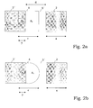
- FIG. 2a shows a schematic illustration to explain the relationship between the areas A W , A Z detected by the sensor and the sensor signal S.
- the square way mark 2 ′ shown with an edge length a has a reflection coefficient r W for the light emitted by the sensor 3 ,
- the edge length c of the likewise square sensor detection area 6 corresponds to the way mark distance d or the edge length a of the way marks.
- the sensor signal S is a linear function of the area Aw or Overlap y of waypoint 2 'and sensor detection area 6.
- the position of the sensor detection area 6 or of the sensor 3 can therefore can be derived from the sensor signal S by a linear function.
- a W Y ⁇ 1-y 2 + arc sin y + ⁇ 2 ,
- the sensor output signals S a , S b can thus be viewed as sinusoidal or cosine-shaped signals.
- FIG. 5 schematically shows an arrangement of the sensors 3a, 3b for Detection of reflected light from an area of the body 1.
- the Markers 2 are on the cylinder surface of a piston rod 21 a hydraulic cylinder arranged.
- the distance of the sensors 3a, 3b in this example is nine times half the way mark distance d.
- Each sensor 3a, 3b has a transmitting light-emitting diode 11 and a receiving photodiode 12 on.
- the arrangement of transmitter LEDs 11 and Receiving photodiode 12 has an angle of 55 °.
- the light exit opening The reflex light barrier is the dimensions of the waymarks 2 adapted so that a maximum of one marker 2 'is illuminated and can contribute to reflection. Due to the curved Surface of the cylinder rod 21 is only a part of the illuminated circular surface directly reflected on the photodiode 12. That emitted Light of the light emitting diode 11 is in the infrared range and has one narrow-band power curve on the sensitivity of the photodiode 12 is adjusted.
- the photocurrent of the receiving photodiode 12 is proportional to the incident light intensity.
- the photodiode 12 can have a daylight filter to avoid interference of the signal by scattered To reduce daylight.
- FIG. 6 schematically shows an arrangement of the sensors 3a, 3b in the cylinder head 22 of a hydraulic cylinder 20.
- This arrangement the sensors 3a, 3b are protected from damage and stray light protected. Furthermore, contamination of the measuring section can occur Gaskets 22a that prevent dirt from entering the cylinder head 22 prevent, be reduced.
- Fig. 7 shows schematically a block diagram of an inventive Control device for controlling the travel of hydraulic cylinders.
- the photocurrent of the receiving photodiode 12 is converted into a voltage and amplified by a transimpedance amplifier 13.
- the signal is band-limited by an anti-aliasing low-pass filter 25 before an analog / digital conversion.
- An analog / digital converter 14 converts the signal for processing by a microcontroller 15.
- the control device also has a clock generator 33 and a pulse width modulation control unit 32.
- the microcontroller 15 controls the position of the piston rod 21 of a hydraulic cylinder 20, taking into account the determined piston rod position x and a target position X 0 .
- the PWM control unit 32 Depending on the difference between the determined piston rod position x and the target position X 0 , the PWM control unit 32 generates a PWM signal, which is amplified by a power amplifier 27.
- a proportional valve 29 is controlled by the power amplifier 27 with the amplified PWM signal to set the required pressure in the hydraulic cylinder 20.
- Fig. 8 shows a schematic representation of an inventive Control device for controlling the lifting height h of a lifting platform 30th
- the scissor lift 30 has one or more hydraulic cylinders 20 for adjusting the lifting height h of a platform 31.
- the evaluation device 4 determines the travel x of the hydraulic cylinder 20 and feeds it to a control unit 23.
- the control unit 23 uses the known geometry of the lifting platform 30 to determine the lifting height h corresponding to the travel path x. To control the platform or driving surface 31, the control unit 23 compares the determined lifting height h with a target height H 0 . Taking into account the control deviation H 0 - h, the control unit 23 carries out a control operation according to a predetermined control characteristic (for example P, PI, PID).
- a predetermined control characteristic for example P, PI, PID
- the control unit controls a hydraulic unit to regulate the lifting height h 24 and the hydraulic valves 26, 29. With the shut-off valve 26, the hydraulic line 28 between the hydraulic cylinder 20 and hydraulic unit 24 can be locked. Via the proportional valve 29, the control unit 23 hydraulic fluid from the hydraulic line 28 and drain the hydraulic cylinder 20 to the travel x to regulate the hydraulic cylinder 20.
- Figure 9 shows a schematic representation of an inventive Control device for controlling the lifting height of a two-part trained stamp lifting platform 30 with two platforms or driving surfaces 31a, 31b and two adjusting devices 20a, 20b.
- the evaluation device 4 determines the lifting heights h a , h b of the two platforms 31a, 31b on the basis of the travel paths x a , x b of the hydraulic cylinders 20a, 20b.
- the control unit 23 forms the control deviations h a - H 0 , h b - H 0 and possibly h a - h b .
- these differences are evaluated by a control device 34.
- Power amplifiers 27a, 27b control the valves of a valve unit 35 for generating the respective hydraulic pressure of the hydraulic cylinders 20a, 20b.
- the control device 34 can perform a position and / or a speed control of the hydraulic cylinders 20a, 20b. In this way, it is possible to raise or lower the platforms 31a, 31b synchronously.
- FIG. 10 schematically shows a hydraulic plan for the synchronous control of the travel paths x a , x b of the hydraulic cylinders 20a, 20b.
- a valve block 37 is provided with a hydraulic unit 24 for generation a fluid pressure connected.
- the valve block 37 has hydraulic valves and a pressure regulator.
- the seat valves 26a, 26b are opening switched to flow.
- the cylinder rods 21a, 21b now pushed out of the cylinder body by the piston pressure. By the movements of the piston rods 21a, 21b can then, for example the driving surfaces 31a, 31b of a stamp lifting platform 30 are raised become.
- the seat valves 26a, 26b are arranged spatially close to the cylinders 20a, 20b and maintain the pressure in the cylinders 20a, 20b and the position of the piston rods 21a, 21b in the idle state.
- the seat valves 26a, 26b and the main valve in the valve block 37 are opened for lowering.
- the hydraulic oil is pushed back by the weight of the hydraulic cylinders 20a, 20b through the hydraulic circuit and collected in a sump.
- the travel paths x a , x b of the hydraulic cylinders 20a, 20b are not the same.
- the microcontroller 15 of the control unit 23 calculates the manipulated variables for the hydraulic cylinders 20a, 20b based on the control deviation.
- the manipulated variables are converted, for example, by the PWM control unit 32 into PWM control signals and amplified by the power amplifiers 27a, 27b.
- Two proportional valves 29a, 29b are arranged in the hydraulic circuit and are controlled by the PWM signal. When actuated, the proportional valves 29a, 29b branch off part of the volume flow of the hydraulic fluid upstream of the seat valves 26a, 26b. This intervention can have a corrective effect on the respective cylinder stroke x a , x b of the hydraulic cylinder 20a, 20b.
- the hydraulic valve 29a, 29b whose cylinder 20a, 20b has a travel path x a , x b that is too large in comparison to the other side is expediently acted upon.
Landscapes
- Engineering & Computer Science (AREA)
- Physics & Mathematics (AREA)
- Mechanical Engineering (AREA)
- General Physics & Mathematics (AREA)
- Fluid Mechanics (AREA)
- General Engineering & Computer Science (AREA)
- Life Sciences & Earth Sciences (AREA)
- Geology (AREA)
- Structural Engineering (AREA)
- Length Measuring Devices With Unspecified Measuring Means (AREA)
- Actuator (AREA)
- Length Measuring Devices By Optical Means (AREA)
Abstract
Description
- Erfassen einer Signalgröße S des Lichts, das von einem Bereich des Körpers reflektiert wird, der zumindest eine Wegmarke und/oder zumindest einen Zwischenraum zwischen den Wegmarken umfaßt;
- Verändern eines Zählerstands Z unter Berücksichtigung des erfaßten Signals S, um eine Bewegung des Körpers zu erfassen;
- Ermitteln des Zusammenhangs zwischen den erfaßten Flächen AW, AZ von Wegmarken und Zwischenräumen anhand des erfaßten Signalwertes,
- Ermitteln der Position x des Körpers anhand des Zählerstands Z und des Zusammenhangs zwischen den erfaßten Flächen AW, AZ.
- Fig. 1
- schematisch ein Ausführungsbeispiel einer erfindungsgemäßen Meßvorrichtung;
- Fig. 2a, b
- schematische Darstellungen zur Erläuterung der vom Sensor erfaßten Flächen von Wegmarke und Zwischenraum;
- Fig. 3
- einen Graphen zur Darstellung der Flächenfunktion;
- Fig. 4a, b
- Signalverläufe einer erfindungsgemäßen Meßvorrichtung;
- Fig. 5
- eine schematische Darstellung einer Reflexlichtschranke;
- Fig. 6
- eine schematische Darstellung einer Sensoranordnung in einem Zylinderkopf;
- Fig. 7
- ein schematisches Blockschaltbild einer erfindungsgemäßen Steuervorrichtung;
- Fig. 8
- schematisch ein Ausführungsbeispiel einer erfindungsgemäßen Steuervorrichtung;
- Fig. 9
- schematisch ein weiteres Ausführungsbeispiel einer erfindungsgemäßen Steuervorrichtung und
- Fig. 10
- ein schematisches Hydraulikschaltbild für eine erfindungsgemäße Steuervorrichtung.
Claims (37)
- Meßvorrichtung zur Ermittlung der Position x eines beweglichen Körpers (1), mit
mehreren Wegmarken (2) auf dem beweglichen Körper (1), einem Sensor (3), der einen zumindest eine Wegmarke (2') und/oder zumindest einen Zwischenraum (5') zwischen den Wegmarken (2) umfassenden Bereich des Körpers (1) erfaßt, und einer Auswertevorrichtung (4), die einen Zählerstand Z unter Berücksichtigung des Sensorausgangssignals S verändert, um eine Bewegung des Körpers (1) zu erfassen, die einen Zusammenhang der vom Sensor (3) erfaßten Bereiche von Wegmarken (2) und Zwischenräumen (5) anhand des Signalwertes des Sensorausgangssignals S ermittelt, und welche die Position x des Körpers (1) basierend auf dem Zählerstand Z und dem ermittelten Zusammenhang bestimmt. - Meßvorrichtung nach Anspruch 1, wobei der Sensor (3) als optischer Reflexionssensor ausgebildet ist, der Licht emittiert und die Menge von reflektiertem Licht erfaßt.
- Meßvorrichtung nach Anspruch 2, wobei der Reflexionsgrad rW der Wegmarken (2) für das vom Sensor (3) emittierte Licht unterschiedlich vom Reflexionsgrad rZ des zwischen den Wegmarken (2) liegenden Zwischenraum (5) ist.
- Meßvorrichtung nach zumindest einem der Ansprüche 1 bis 3, wobei die Wegmarken (2) in Bewegungsrichtung des Körpers (1) in einem gleichmäßigem Abstand d angeordnet und gleichförmig ausgebildet sind.
- Meßvorrichtung nach zumindest einem der Ansprüche 1 bis 4, wobei der Abstand d zwischen den Wegmarken (2) der Abmessung a der Wegmarken (2) in Bewegungsrichtung des Körpers (1) entspricht, und die Abmessung c der beleuchteten Fläche in Bewegungsrichtung des Körpers (1) dem Wegmarkenabstand d entspricht.
- Meßvorrichtung nach zumindest einem der Ansprüche 1 bis 5, wobei der Sensor (3) eine annähernd kreisförmige Fläche des Körpers (1) erfaßt.
- Meßvorrichtung nach zumindest einem der Ansprüche 1 bis 6, wobei zumindest zwei Sensoren (3a, 3b) vorgesehen sind, die in Bewegungsrichtung des Körpers (1) um das Vielfache des halben Wegmarkenabstands d versetzt sind, und die Auswertevorrichtung (4) die Position x des Körpers (1) anhand der Ausgangssignale Sa, Sb der Sensoren (3a, 3b) ermittelt.
- Meßvorrichtung nach Anspruch 7, wobei die Auswertevorrichtung (4) anhand der Phasenbeziehung der Sensorausgangssignale Sa, Sb die Bewegungsrichtung des Körpers (1) ermittelt und den Zählerstand Z entsprechend inkrementiert oder dekrementiert, insbesondere anhand der Maxima und/oder Minima der Sensorsignale Sa, Sb.
- Meßvorrichtung nach zumindest einem der Ansprüche 1 bis 6, wobei die Auswertevorrichtung (4) eine Signalverarbeitungseinrichtung (16) aufweist, die das Sensorausgangssignal S verarbeitet, um Signalamplituden zu normieren, einen Offset bzw. Mittelwert zu entfernen und/oder Störungen im Signal zu reduzieren, insbesondere durch Filterung des Signals S.
- Meßvorrichtung nach zumindest einem der Ansprüche 7 bis 9, wobei die Auswertevorrichtung (4) eine Divisionseinrichtung (7) aufweist, die das Ausgangssignal Sa eines ersten Sensors (3a) durch das Ausgangssignal Sb eines zweiten Sensors (3b) dividiert, um die Anteile der von den Sensoren (3a, 3b) erfaßten Flächen AW, AZ von Wegmarke (2') und Zwischenraum (5') aus dem erhaltenen Divisionssignal D zu ermitteln.
- Meßvorrichtung nach zumindest einem der Ansprüche 7 bis 10, wobei die Auswertevorrichtung (4) durch Auswertung von trigonometrischen Funktionen der sinus- bzw. cosinusförmigen Sensorausgangssignale Sa, Sb die Phasenbeziehung zwischen den Wegmarken (2) und den Sensoren (3a, 3b) unter Erhalt eines Interpolationssignals I ermittelt, insbesondere durch Division der sinus- bzw. cosinusförmigen Sensorausgangssignale Sa, Sb und Anwendung der Arkustangensfunktion auf das erhaltene Divisionssignal D, und die Lage der Sensoren (3a, 3b) im Verhälnis zu den Wegmarken (2) bestimmt.
- Meßvorrichtung nach zumindest einem der Ansprüche 1 bis 11, wobei die Auswertevorrichtung (4) eine Signalkorrektureinrichtung (8) aufweist, die erfaßte Sensorsignalwerte korrigiert bzw. normiert.
- Meßvorrichtung nach zumindest einem der Ansprüche 1 bis 12, wobei die Auswertevorrichtung (4) eine Speichereinrichtung (9) aufweist, welche die erfaßten Signalwerte und/oder Maximalwerte und/oder Minimalwerte des Sensorausgangssignals S bzw. der Sensorausgangssignale Sa, Sb speichert.
- Meßvorrichtung nach Anspruch 13, wobei die Signalkorrektureinrichtung (8) den Wert eines erfaßten Sensorausgangssignals S, Sa, Sb mit einem gespeicherten Wert einer vorherigen Bewegung des Körpers (1) vergleicht und den erfaßten Signalwert unter Berücksichtigung der gespeicherten Werte korrigiert bzw. normiert.
- Meßvorrichtung nach zumindest einem der Ansprüche 12 bis 14, wobei die Signalkorrektureinrichtung (8) das Divisionssignal D und/oder das Interpolationssignal I anhand von vorher erhaltenen Werten des entsprechenden Signals korrigiert bzw. normiert, insbesondere unter Berücksichtigung der Maximal- und/oder Minimalwerte des vorherigen Signals.
- Meßvorrichtung nach Anspruch 14 oder 15, wobei die Speichereinrichtung (9) das Divisionssignal D und/oder das Interpolationssignal I einer vorherigen Bewegung des Körpers und/oder Maximalwerte und/oder Minimalwerte des entsprechenden Signals speichert und die Signalkorrektureinrichtung (8) das Divisionssignal D und/oder das Interpolationssignal I anhand der gespeicherten Werte korrigiert bzw. normiert.
- Meßvorrichtung nach zumindest einem der Ansprüche 1 bis 16, wobei ein Korrektur-Sensor vorgesehen ist, der in Bewegungsrichtung des Körpers (1) in einem bestimmten Abstand von dem Sensor (3) bzw. den Sensoren (3a, 3b) angeordnet ist, und dessen Signal von der Signalkorrektureinrichtung (8) zur Korrektur bzw. zur Normierung des Signals S bzw. der Signale Sa, Sb der anderen Sensoren (3, 3a, 3b ) verwendet wird, insbesondere indem die Signalkorrektureinrichtung (8) anhand der Signalwerte des Korrektur-Sensors die Maximalwerte und/oder Minimalwerte des bzw. der anderen Sensoren (3, 3a, 3b ) vorbestimmt.
- Meßvorrichtung nach zumindest einem der Ansprüche 1 bis 17, wobei der Sensor (3) als Reflexlichtschranke (10) mit einer Sendeleuchtdiode (11) und einer Empfangsphotodiode (12) ausgebildet ist, und der Photostrom der Empfangsphotodiode (12) von einem Transimpedanzverstärker bzw. Strom-Spannungs-Wandler (13) verstärkt wird.
- Meßvorrichtung nach zumindest einem der Ansprüche 1 bis 18, wobei die Auswertevorrichtung (4) einen Analog/ Digital-Wandler (14) und einen Mikrocontroller (15) aufweist, der den Zählerstand Z für die Anzahl der Maxima und/oder Minima des digitalisierten Sensorausgangssignals S führt und das Verhältnis der Flächen Aw, Az von Wegmarke (2') und Zwischenraum (5') anhand der digitalisierten Sensorsignalwerte ermittelt und gegebenenfalls die Korrektur und Speicherung von Signalen ausführt.
- Meßvorrichtung nach zumindest einem der Ansprüche 1 bis 19, wobei die Wegmarken (2) durch Lasergravur auf dem bewegten Körper (1) aufgebracht sind.
- Meßvorrichtung nach zumindest einem der Ansprüche 1 bis 18 wobei die Wegmarken (2) auf der Zylinderoberfläche einer Kolbenstange (21) eines Hydraulikzylinders (20) angeordnet sind.
- Meßvorrichtung nach Anspruch 21, wobei der Sensor (3) in einem Zylinderkopf (22) des Hydraulikzylinders (20) angeordnet ist.
- Verwendung der Meßvorrichtung nach zumindest einem der Ansprüche 1 bis 22 zur Messung der Position x einer Kolbenstange (21), insbesondere zur Messung des Verfahrwegs der Kolbenstange (21) eines Hydraulikzylinders (20).
- Steuervorrichtung zur Steuerung des Verfahrwegs x von Hydraulikzylindern mit
einer Meßvorrichtung nach zumindest einem der Ansprüche 1 bis 22 zur Erfassung des Verfahrwegs x der Kolbenstange (21) des Hydraulikzylinders (20),
einer Steuereinheit (23) und
einer Hydraulikeinheit (24) zur Erzeugung eines Fluiddruckes zur Betätigung des Hydraulikzylinders (20), wobei
die Steuereinheit (23) den von der Meßvorrichtung ermittelten Verfahrweg x der Kolbenstange (21) mit einem vorgegebenen Soll-Weg X0 der Kolbenstange (21) vergleicht und die Hydraulikeinheit (24) zur Erzeugung eines entsprechenden Fluiddruckes und/oder ein Hydraulikventil (26) ansteuert, um den vorgegebenen Soll-Weg X0 durch Druckbeaufschlagung eines mit der Kolbenstange (21) verbundenen Kolbens (25) des Hydraulikzylinders (20) zu erzielen. - Steuervorrichtung nach Anspruch 24, wobei
mehrere von der Hydraulikeinheit (24) über ein Hydraulikventil (26) betätigte Hydraulikzylinder (20) vorgesehen sind, deren jeweilige Kolbenstangenpositionen bzw. Verfahrwege von der Meßvorrichtung ermittelt und von der Steuereinheit (23) gesteuert werden, wobei
die Steuereinheit (23) die Hydraulikeinheit (24) und/oder das Ventil (26) derart ansteuert, daß die relativen Positionen der Kolbenstangen (21) zueinander eine vorgegebene Beziehung aufweisen, insbesondere gleich weit aus ihrem jeweiligen Hydraulikzylinder (20) herausbewegt sind bzw einen gleichen Verfahrweg aufweisen. - Steuervorrichtung nach Anspruch 24 oder 25, die zumindest einen von der Steuereinheit (23) angesteuerten Leistungsverstärker (27) und zumindest ein von diesem angesteuertes Proportionalventil (29) aufweist, das in der Hydaulikleitung (28) zwischen Hydraulikeinheit (24) und Hydraulikzylinder (20) angeordnet ist und bei Betätigung Fluid bzw. Druck aus der Hydaulikleitung (28) abläßt, wobei
die Steuereinheit (23) den Leistungsverstärker (27) derart ansteuert, daß der vorgegebene Soll-Weg X0 der Kolbenstange (21) erzielt wird bzw. die relativen Positionen der Kolbenstangen (21) zueinander eine vorgegebene Beziehung aufweisen. - Verwendung der Steuervorrichtung nach zumindest einem der Ansprüche 24 bis 26 zur Steuerung der Hydraulikzylinder (20) von Hebebühnen (30), insbesondere um einen gleichmäßigen Verfahrweg der Hydraulikzylinder (20) zu erzielen.
- Hebebühne, insbesondere für Kraftfahrzeuge, mit zumindest einem Hydraulikzylinder (20) zum Anheben bzw. Absenken einer Plattform (31) oder eines Tragwerks und einer Steuervorrichtung nach zumindest einem der Ansprüche 24 bis 27 zum Steuern des Hydraulikzylinders (20).
- Meßverfahren zur Ermittlung der Position x eines beweglichen Körpers (1) mit mehreren Wegmarken (2), das folgende Schritte enthält:Erfassen einer Signalgröße S des Lichts, das von einem Bereich des Körpers reflektiert wird, der zumindest eine Wegmarke (2') und/oder zumindest einen Zwischenraum (5') zwischen den Wegmarken (2) umfaßt,Verändern eines Zählerstands Z unter Berücksichtigung des erfaßten Signals S, um eine Bewegung des Körpers (1) zu erfassen,Ermitteln des Zusammenhangs zwischen den vom Sensor erfaßten Flächen AW, AZ von Wegmarke (2') und Zwischenraum (5') anhand des Signalwertes S,Bestimmen der Position x des Körpers (1) anhand des Zählerstands Z und des ermittelten Zusammenhangs.
- Meßverfahren nach Anspruch 29, wobei Signale Sa, Sb für das reflektierte Licht von zumindest zwei Bereichen des Körpers (1), die in Bewegungsrichtung des Körpers (1) um das Vielfache des halben Wegmarkenabstands d versetzt sind, erfaßt werden.
- Meßverfahren nach Anspruch 30, wobei anhand der Phasenbeziehung zwischen den erfaßten Signalen Sa, Sb die Bewegungsrichtung des Körpers (1) ermittelt und der Zählerstand Z entsprechend inkrementiert oder dekrementiert wird.
- Meßverfahren nach zumindest einem der Ansprüche 29 bis 31, wobei das erfaßte Signal S bzw. die erfaßten Signale Sa, Sb vor der Auswertung gefiltert, normiert und/oder von einem Offset bzw. Mittelwert befreit wird.
- Meßverfahren nach zumindest einem der Ansprüche 29 bis 32, wobei ein erstes erfaßtes Signal Sa durch ein zweites erfaßtes Signal Sb dividiert wird, um das Verhältnis der Flächen AW, AZ von erfaßter Wegmarke (2') und erfaßtem Zwischenraum (5') aus dem erhaltenen Divisionssignal D zu ermitteln.
- Meßverfahren nach zumindest einem der Ansprüche 29 bis 33, wobei die erfaßten Signalwerte und/oder Maximalwerte und/oder Minimalwerte der Signale S, Sa, Sb gespeichert werden und ein erfaßter Signalwert unter Berücksichtigung der gespeicherten Werte einer vorherigen Bewegung des Körpers (1) korrigiert bzw. normiert wird.
- Meßverfahren nach zumindest einem der Ansprüche 29 bis 34, wobei zur Korrektur bzw. zur Normierung des erfaßten Signalwerts für einen bestrahlten Bereich des Körpers (1) zuvor ein Korrektur-Signal erfaßt wird, anhand dessen die Maximalwerte und/oder Minimalwerte des Signals für den Bereich bestimmt werden und/oder mit denen der Signalwert korrigiert bzw. normiert wird.
- Steuerverfahren zur Steuerung des Verfahrwegs x von Hydraulikzylindern, das die Position x der Kolbenstange (21) des Hydraulikzylinders (20) nach einem Meßverfahren gemäß einem der Ansprüche 29 bis 35 ermittelt, die ermittelte Position x der Kolbenstange (21) mit einer vorgegebenen Soll-Position X0 der Kolbenstange (21) vergleicht und eine Hydraulikeinheit (24) zur Erzeugung eines Fluiddruckes zur Betätigung des Hydraulikzylinders (20) und/oder ein Ventil (26) ansteuert, um die vorgegebene Soll-Position X0 zu erzielen.
- Steuerverfahren nach Anspruch 36, wobei die Positionen bzw. Verfahrwege der Kolbenstangen (21) von mehreren Hydraulikzylindern (20) ermittelt und miteinander verglichen werden, und die Hydraulikeinheit (24), ein Hydraulikventil (26) und/oder ein zwischen Hydraulikeinheit (24) und Hydraulikzylinder (20) angeordnetes Proportionalventil (29) derart angesteuert werden, daß die relativen Positionen der Kolbenstangen (21) zueinander eine vorgegebene Beziehung aufweisen, insbesondere gleich weit aus ihrem jeweiligen Hydraulikzylinder (20) herausbewegt sind bzw. einen gleichen Verfahrweg aufweisen.
Applications Claiming Priority (2)
| Application Number | Priority Date | Filing Date | Title |
|---|---|---|---|
| DE10242630 | 2002-09-13 | ||
| DE2002142630 DE10242630A1 (de) | 2002-09-13 | 2002-09-13 | Meß-und Steuervorrichtung für Hebebühnen |
Publications (2)
| Publication Number | Publication Date |
|---|---|
| EP1398602A2 true EP1398602A2 (de) | 2004-03-17 |
| EP1398602A3 EP1398602A3 (de) | 2004-11-03 |
Family
ID=31724738
Family Applications (1)
| Application Number | Title | Priority Date | Filing Date |
|---|---|---|---|
| EP03019591A Withdrawn EP1398602A3 (de) | 2002-09-13 | 2003-09-03 | Positionsmess- und Steuervorrichtung für Hebebühnen |
Country Status (2)
| Country | Link |
|---|---|
| EP (1) | EP1398602A3 (de) |
| DE (1) | DE10242630A1 (de) |
Cited By (7)
| Publication number | Priority date | Publication date | Assignee | Title |
|---|---|---|---|---|
| EP1655581A1 (de) * | 2004-10-27 | 2006-05-10 | Electricfil Automotive | Vorrichtung zur Erfassung mindestens der Position eines beweglichen Ziels |
| EP2428481A1 (de) * | 2010-09-13 | 2012-03-14 | MAHA Maschinenbau Haldenwang GmbH & Co. KG | Hebebühne |
| CN103241675A (zh) * | 2013-05-02 | 2013-08-14 | 浙江省建设机械集团有限公司 | 多油缸顶升系统用直测数显位移及自动平衡装置 |
| NL1040225C2 (en) * | 2013-05-23 | 2014-11-26 | Janssen Prec Engineering | Fibre based cryogenic optical encoder. |
| CN107725510A (zh) * | 2017-11-16 | 2018-02-23 | 重庆三峡学院 | 同步驱动小吊机支腿的调平控制油路 |
| CN110388871A (zh) * | 2018-04-16 | 2019-10-29 | 永恒力股份公司 | 用于运行地面搬运车的光学传感器单元的方法和光学传感器单元 |
| CN112489127A (zh) * | 2020-12-14 | 2021-03-12 | 石倩 | 基于人工智能的升降台控制方法及系统 |
Families Citing this family (6)
| Publication number | Priority date | Publication date | Assignee | Title |
|---|---|---|---|---|
| DE102006031382A1 (de) * | 2006-07-07 | 2008-01-24 | Zf Friedrichshafen Ag | Anordnung zur Druckregelung einer Getriebestelleinrichtung |
| DE102010033069A1 (de) | 2009-08-20 | 2011-03-17 | Schaeffler Technologies Gmbh & Co. Kg | Hydraulikzylinder für eine Kupplungsausrückvorrichtung |
| DE102013007292B4 (de) * | 2013-04-26 | 2016-08-25 | Siemag Tecberg Gmbh | Verfahren zur Geschwindigkeitsregelung einer Klemm- und Hub-Vorrichtung sowie Regelvorrichtung zur Durchführung des Verfahrens |
| DE102015104201A1 (de) | 2015-03-20 | 2016-09-22 | Jungheinrich Aktiengesellschaft | Fluidzylinder |
| DE102015121571A1 (de) * | 2015-09-16 | 2017-03-16 | Weber-Hydraulik Gmbh | Optischer Sensor, insbesondere für Zylinder, sowie Verwendung |
| DE102016117800A1 (de) * | 2016-09-21 | 2018-03-22 | Jungheinrich Aktiengesellschaft | Fluidzylinder mit einer optischen Sensoreinheit |
Citations (2)
| Publication number | Priority date | Publication date | Assignee | Title |
|---|---|---|---|---|
| WO1995001510A1 (en) * | 1993-07-02 | 1995-01-12 | Partek Cargotec Oy | A hydraulic, pneumatic or another similar cylinder |
| DE19544948A1 (de) * | 1995-12-01 | 1997-06-05 | Gemac Ges Fuer Mikroelektronik | Digitale Interpolationseinrichtung mit Amplituden- und Nullageregelung der Eingangssignale |
Family Cites Families (5)
| Publication number | Priority date | Publication date | Assignee | Title |
|---|---|---|---|---|
| US4860639A (en) * | 1984-12-11 | 1989-08-29 | Bridgestone Corporation | Flexible tubular wall actuator with end-mounted strain gauge |
| DE3634730A1 (de) * | 1986-10-11 | 1988-04-21 | Klaus Huegler | Arbeitszylinder, insbesondere pneumatikzylinder fuer komponenten von handlingautomaten |
| DE29613725U1 (de) * | 1996-08-08 | 1996-10-02 | Kunze, Harald, 71106 Magstadt | Einrichtung zum Ermitteln einer Position zweier zueinander beweglichen Teile |
| DE10014194A1 (de) * | 1999-04-10 | 2001-01-25 | Leuze Electronic Gmbh & Co | Vorrichtung zur Bestimmung der Position einer Kolbenstange |
| US6327791B1 (en) * | 1999-06-09 | 2001-12-11 | The Government Of The United States As Represented By The Secretary Of Commerce | Chain code position detector |
-
2002
- 2002-09-13 DE DE2002142630 patent/DE10242630A1/de not_active Withdrawn
-
2003
- 2003-09-03 EP EP03019591A patent/EP1398602A3/de not_active Withdrawn
Patent Citations (2)
| Publication number | Priority date | Publication date | Assignee | Title |
|---|---|---|---|---|
| WO1995001510A1 (en) * | 1993-07-02 | 1995-01-12 | Partek Cargotec Oy | A hydraulic, pneumatic or another similar cylinder |
| DE19544948A1 (de) * | 1995-12-01 | 1997-06-05 | Gemac Ges Fuer Mikroelektronik | Digitale Interpolationseinrichtung mit Amplituden- und Nullageregelung der Eingangssignale |
Cited By (9)
| Publication number | Priority date | Publication date | Assignee | Title |
|---|---|---|---|---|
| EP1655581A1 (de) * | 2004-10-27 | 2006-05-10 | Electricfil Automotive | Vorrichtung zur Erfassung mindestens der Position eines beweglichen Ziels |
| EP2428481A1 (de) * | 2010-09-13 | 2012-03-14 | MAHA Maschinenbau Haldenwang GmbH & Co. KG | Hebebühne |
| CN103241675A (zh) * | 2013-05-02 | 2013-08-14 | 浙江省建设机械集团有限公司 | 多油缸顶升系统用直测数显位移及自动平衡装置 |
| NL1040225C2 (en) * | 2013-05-23 | 2014-11-26 | Janssen Prec Engineering | Fibre based cryogenic optical encoder. |
| CN107725510A (zh) * | 2017-11-16 | 2018-02-23 | 重庆三峡学院 | 同步驱动小吊机支腿的调平控制油路 |
| CN107725510B (zh) * | 2017-11-16 | 2023-07-07 | 中国民用航空飞行学院 | 同步驱动小吊机支腿的调平控制油路 |
| CN110388871A (zh) * | 2018-04-16 | 2019-10-29 | 永恒力股份公司 | 用于运行地面搬运车的光学传感器单元的方法和光学传感器单元 |
| CN112489127A (zh) * | 2020-12-14 | 2021-03-12 | 石倩 | 基于人工智能的升降台控制方法及系统 |
| CN112489127B (zh) * | 2020-12-14 | 2023-06-23 | 一方智诚(珠海)科技有限公司 | 基于人工智能的升降台控制方法及系统 |
Also Published As
| Publication number | Publication date |
|---|---|
| DE10242630A1 (de) | 2004-03-18 |
| EP1398602A3 (de) | 2004-11-03 |
Similar Documents
| Publication | Publication Date | Title |
|---|---|---|
| EP1398602A2 (de) | Positionsmess- und Steuervorrichtung für Hebebühnen | |
| EP3278302A1 (de) | Bewegungsmesssystem einer maschine und verfahren zum betreiben des bewegungsmesssystems | |
| EP0513427A1 (de) | Interferentielle Positionsmessvorrichtung | |
| DE102008011057A1 (de) | Messvorrichtung für ein Werkstück, das auf einem Einspanntisch gehaltert ist | |
| EP2513875B1 (de) | Spektralsensor zur prüfung von wertdokumenten | |
| EP1003012A2 (de) | Optische Positionsmesseinrichtung | |
| EP3663722A1 (de) | Verfahren zur automatischen kalibrierung eines magnetischen sensors und magnetischer sensor | |
| EP0669519A2 (de) | Positionsmessvorrichtung | |
| WO2011000870A1 (de) | Bearbeitungsanlage | |
| DE1905392A1 (de) | Vorrichtung zum Erzeugen von elektrischen Signalen mittels eines Skalengitters,das relativ zu einem Indexgitter bewegbar ist | |
| DE10056329B4 (de) | Optisches Abstandsmeßverfahren und Abstandssensor | |
| DE10116672B4 (de) | Verfahren und Vorrichtung zur Materialbearbeitung | |
| DE102022202778B4 (de) | System und Verfahren zur konfokal-chromatischen Linienabstandsmessung | |
| EP3312114B1 (de) | Verfahren und vorrichtung zur lageerfassung einer laufenden warenbahn | |
| DE2901980A1 (de) | Einrichtung zur steuerung einer druckmaschine | |
| EP1427985A1 (de) | Positionsmesseinrichtung und verfahren zum betrieb einer positionsmesseinrichtung | |
| EP3267367A1 (de) | Zählscheibenvorrichtung | |
| EP1857280A2 (de) | Rotationsdruckmaschine mit mindestens einem Farbwerk und mit einem Inline-Farbmesssystem | |
| EP0635701A1 (de) | Längen- oder Winkelmesseinrichtung | |
| DE19719499A1 (de) | Geschwindigkeitsmesseinrichtung | |
| AT514188A1 (de) | Biegewinkel-Messvorrichtung für eine Biegepresse | |
| EP0092504A2 (de) | Faseroptische Messanordnung mit einem Geber und einer Messelektronik zur Lagemessung | |
| DE10101443B4 (de) | Verfahren zur Ermittlung eines Schnittbildes einer Objektstruktur | |
| DE19936181A1 (de) | Optische Positionsmeßeinrichtung | |
| EP4636361B1 (de) | Vorrichtung und verfahren zur positions-, längen- oder winkelbestimmung |
Legal Events
| Date | Code | Title | Description |
|---|---|---|---|
| PUAI | Public reference made under article 153(3) epc to a published international application that has entered the european phase |
Free format text: ORIGINAL CODE: 0009012 |
|
| AK | Designated contracting states |
Kind code of ref document: A2 Designated state(s): AT BE BG CH CY CZ DE DK EE ES FI FR GB GR HU IE IT LI LU MC NL PT RO SE SI SK TR |
|
| AX | Request for extension of the european patent |
Extension state: AL LT LV MK |
|
| PUAL | Search report despatched |
Free format text: ORIGINAL CODE: 0009013 |
|
| AK | Designated contracting states |
Kind code of ref document: A3 Designated state(s): AT BE BG CH CY CZ DE DK EE ES FI FR GB GR HU IE IT LI LU MC NL PT RO SE SI SK TR |
|
| AX | Request for extension of the european patent |
Extension state: AL LT LV MK |
|
| 17P | Request for examination filed |
Effective date: 20050426 |
|
| AKX | Designation fees paid |
Designated state(s): DE IT |
|
| 17Q | First examination report despatched |
Effective date: 20060809 |
|
| STAA | Information on the status of an ep patent application or granted ep patent |
Free format text: STATUS: THE APPLICATION IS DEEMED TO BE WITHDRAWN |
|
| 18D | Application deemed to be withdrawn |
Effective date: 20100817 |