EP1398616A2 - Détermination du changement de viscosité d'une mesure de la vitesse - Google Patents
Détermination du changement de viscosité d'une mesure de la vitesse Download PDFInfo
- Publication number
- EP1398616A2 EP1398616A2 EP03077479A EP03077479A EP1398616A2 EP 1398616 A2 EP1398616 A2 EP 1398616A2 EP 03077479 A EP03077479 A EP 03077479A EP 03077479 A EP03077479 A EP 03077479A EP 1398616 A2 EP1398616 A2 EP 1398616A2
- Authority
- EP
- European Patent Office
- Prior art keywords
- fluid
- viscosity
- heated portion
- rise time
- time
- Prior art date
- Legal status (The legal status is an assumption and is not a legal conclusion. Google has not performed a legal analysis and makes no representation as to the accuracy of the status listed.)
- Granted
Links
Images

Classifications
-
- G—PHYSICS
- G01—MEASURING; TESTING
- G01K—MEASURING TEMPERATURE; MEASURING QUANTITY OF HEAT; THERMALLY-SENSITIVE ELEMENTS NOT OTHERWISE PROVIDED FOR
- G01K3/00—Thermometers giving results other than momentary value of temperature
- G01K3/08—Thermometers giving results other than momentary value of temperature giving differences of values; giving differentiated values
- G01K3/10—Thermometers giving results other than momentary value of temperature giving differences of values; giving differentiated values in respect of time, e.g. reacting only to a quick change of temperature
-
- G—PHYSICS
- G01—MEASURING; TESTING
- G01N—INVESTIGATING OR ANALYSING MATERIALS BY DETERMINING THEIR CHEMICAL OR PHYSICAL PROPERTIES
- G01N11/00—Investigating flow properties of materials, e.g. viscosity, plasticity; Analysing materials by determining flow properties
- G01N11/10—Investigating flow properties of materials, e.g. viscosity, plasticity; Analysing materials by determining flow properties by moving a body within the material
- G01N11/12—Investigating flow properties of materials, e.g. viscosity, plasticity; Analysing materials by determining flow properties by moving a body within the material by measuring rising or falling speed of the body; by measuring penetration of wedged gauges
Definitions
- This invention relates generally to measuring viscosity and more particularly to a method and apparatus for measuring the change in viscosity of a fluid as the condition of the fluid deteriorates.
- Hydraulic oil such as lubricating oil for an internal combustion engine inevitably experiences changes in its viscosity over time as a function of oil grade, temperature, state of deterioration and other operational parameters.
- Oil viscosity is an important property because it defines the oil film thickness between moving parts of an engine. It also affects cold crank capability, fuel consumption and for some engines it influences the ability to control emissions such as in a diesel injection system with a hydraulic booster. Oil viscosity may also be used to determine the end of the oil's useful life.
- a predetermined threshold value of oil viscosity may be used alone or in conjunction with other oil properties such as oil acidity, particle count, content of certain additives and level of contamination to signify that a volume of oil has reached the end of its useful life and needs to be replaced or reconditioned.
- One known method for determining viscosity employs an arrangement that purportedly measures the viscosity of a fluid by determining the time required for a standard element to travel a predetermined distance through the fluid.
- This arrangement is not capable of in-situ measurements of oil viscosity, which may be desirable in many applications such as in the automobile industry.
- Other devices and methods are known for measuring viscosity that require samples of the liquid in question to be taken to a laboratory of other facility for analysis. These techniques are not suitable for in-situ measurements.
- One exemplary embodiment of the present invention provides an in-situ method and apparatus for measuring the change in viscosity of a lubricant as the quality of the lubricant deteriorates during operational use.
- One aspect of the present invention allows for the correlation of the heat convection properties of the lubricant to the lubricant's viscosity.
- a heating means may be provided for locally increasing the lubricant's temperature. At least a portion of the heated lubricant may then rise within the bulk lubricant volume due to the heated portion's reduced density.
- An operational rise time may then be determined, which may be determined after a vehicle is shut down, for example, to determine the necessity of changing or treating the bulk lubricant.
- the operational rise time may be the difference between the actuation of a heat pulse from the heating means to heat a portion of the bulk lubricant and the arrival of the heated portion at a predetermined distance from the heating means. The operational rise time may then be used to determine the bulk fluid's viscosity.
- An alternate embodiment allows for the operational rise time to be the amount of time it takes the heated portion to rise from a position proximate the point at which it is heated to a position proximate a second point that is a known distance from the first point.
- Yet another alternate embodiment allows for determining the heated portion's average velocity, which may be determined as a function of the temperature difference between the heated lubricant portion and the rest of the bulk lubricant volume. The average velocity may also be a function of shear forces within the lubricant, which are determined by the lubricant's viscosity.
- One aspect of the present invention allows for creating a set of look up tables containing baseline rise times at a known temperature for a set of bulk fluids having a known viscosity.
- the operational rise time may then be compared to the appropriate baseline rise time contained in the look up table to determine the viscosity change of the bulk lubricant.
- the baseline rise time data may be interpolated to determine qualitative and/or quantitative information regarding the viscosity of the bulk lubricant in response to determining the operational rise time. This information may then be used to determine whether the bulk lubricant needs to be changed or treated.
- One embodiment of the present invention allows for a temperature sensor to take a first temperature at a predetermined height to establish a baseline temperature of the bulk lubricant at that height.
- the heating means may heat a portion of the bulk lubricant at a predetermined point below the predetermined height.
- the amount of time it takes the heated portion to rise from the heating means to the predetermined height may be measured by determining when the temperature change occurs at the predetermined height. A change, if any, in the viscosity of the fluid may then be determined.
- Another aspect of an exemplary embodiment of the present invention allows for at least one temperature sensor to be used in a quantity of bulk oil for measuring a temperature as a quantity of heated lubricant passes a known point.
- two temperature sensors may be used to measure temperature change between a first point and a second point in the bulk oil as the heated oil passes between those points.
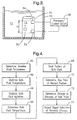
- FIG. 1 illustrates a cross section of a container 10 for holding a quantity of bulk fluid 12 such as petroleum-based oil used as a lubricant for lubricating and cooling moving components of the internal combustion engine of an automobile, for example.
- a heating means 14 may be provided to locally heat a portion 16 of the bulk fluid 12.
- the heating means 14 may be a conventional heat source such as a smart heating source, for example, adapted to control voltage and current. In alternate embodiments the heating means 14 may be other conventional devices such as radiative, resistive, and inductive heaters, for example.
- a temperature sensor 18 may be provided to measure a change in temperature at a predetermined point above the heating means 14.
- the temperature sensor 18 may be a conventional device such as a resistive thermal device ("RTD"), thermocouple, thermometer or other devices known in the art.
- RTD resistive thermal device
- the heated portion 16 of bulk fluid 12 will rise after being heated due to its lower density relative to the bulk fluid 12.
- One exemplary embodiment of the present invention allows for correlating the amount of time it takes the heated portion 16 to travel a known distance through the bulk fluid 12 with viscosity in order to measure a change in viscosity of the bulk fluid 12.
- the heated portion 16 may cool as it rises in the bulk fluid 12 due to the thermal conductivity of the bulk fluid 12 and the heated portion 16.
- thermal conductivity of petroleum-based lubricants such as those used in automobiles, for example, are substantially equal and whatever effect thermal conductivity has on the heated portion 16 is substantially the same among the lubricants.
- Other embodiments of the present invention may take into account differences in thermal conductivity among bulk fluids to the extent the differences impact the determination of viscosity changes in those fluids.
- the temperature sensor 18 may be used to detect a change in temperature of the bulk fluid 12 at a predetermined point or height B above the heating means 14. After heating, the velocity of the portion of heated fluid 16 when moving distance d between points A and B is a function of at least: a) the temperature difference between the bulk fluid 12 and the heated portion 16, and b) the viscosity of the bulk fluid 12. In one exemplary embodiment the distance d may be between about one (1) to two (2) centimeters and the temperature difference between the bulk fluid 12 and the heated portion 16 may be about 5 degrees Celsius. Distance d and the temperature difference between the heated portion 16 and the bulk fluid 12 may vary in alternate embodiments of the present invention depending on specific design, performance and other parameters.
- the temperature difference between the heated portion 16 and the bulk fluid 12 may be a function of the duration of a heat pulse generated by the heating means 14. The longer the heat pulse the greater the temperature differential. It is desirable to provide a heat pulse that results in a sufficiently stable or defined heated portion 16. This allows for the heated portion 16 to travel through the predetermined distance without diffusing too much into the bulk liquid 12 or otherwise having its physical properties degrade before it reaches the temperature sensor 18, for example. Similarly, if the heated portion 16 is not sufficiently heated it may not travel to the temperature sensor 18 with sufficient characteristics for the sensor 18 to detect a temperature change.
- a heat pulse generally between about 0.5 and 1.0 seconds allows for the heated portion 16 to travel an appropriate distance to have its operational rise time determined.
- Alternate embodiments may provide for a heat pulse of greater or lesser values depending at design parameters of the viscosity sensor.
- the heat pulse may be as short as about 0.10 seconds.
- the present invention is not limited to any specific time duration for heating portion 16.
- the operational rise time may be defined as the time difference between the time a heat pulse from heating means 14 is actuated and the time the heated portion 16 "arrives", or is initially detected, at a point a known distance away such as point B proximate the temperature sensor 18.
- the temperature sensor 18 may detect a localized change in temperature of the bulk fluid 12 that is indicative of the "arrival" of the heated portion 16. As the heated portion 16 rises toward height B the temperature sensor 18 will detect a temperature change in the bulk liquid 12 proximate the temperature sensor 18. This is due to the heated portion 16 rising sufficiently close to the temperature sensor 18 so that the sensor may measure a local change in temperature of the bulk fluid 12.
- the "arrival" of the heated portion 16 may be detected by a laser diode that detects a change in the index of refraction of the heated portion 16 as it passes near the sensing area.
- the temperature sensor 18 may be configured to send a data signal to a processor 22 that the heated portion 16 has been detected.
- the processor 22 may then calculate the operational rise time and/or the average velocity of the heated portion 16.
- the operational rise time may then be compared to a baseline rise time for that bulk fluid 12 via a lookup table stored in a database accessible by the processor 22, for example.
- the baseline rise time may be determined for the bulk fluid 12 at a selected temperature when the bulk fluid's 12 viscosity is known such as before the bulk fluid 12 is subjected to operating conditions in container 10.
- the operational rise time of the heated portion 16 may be calculated over a different distance d, such as the time it takes the heated portion 16 to move between any two known points, provided that the baseline rise time is calculated using the same points.
- measuring changes in temperature over a distance d should not be construed as a limitation of the present invention.
- the assignee of the present invention has determined through empirical experimentation that the difference between the baseline and operating rise times is indicative of a change in viscosity of the bulk fluid 12. The viscosity of the surrounding bulk liquid 12 will affect the rise rate of the heated portion 16. The greater the viscosity of the surrounding bulk fluid 12 the more slowly the heated portion 16 will rise.
- a control circuit 20 and the processor 22 may be provided for data analysis and as means for controlling the temperature sensor 18, heat source 14 and/or a display device 24.
- the control circuit 20 and processor 22 may be separate components or they may be combined into one unit as will be recognized by those skilled in the art.
- Processor 22 may be configured with appropriate software to calculate the difference between the baseline rise time and the operational rise time for a selected bulk fluid 12. The difference may then be used to determine whether that bulk fluid 12 has experienced a change in its viscosity.
- the processor 22 may be programmed to express a change in viscosity in qualitative and/or quantitative terms.
- An electronic data signal indicative of any change in the viscosity of the bulk liquid 12 may be generated by the processor 22 and sent to a display device 24, for example, by the control circuit 20.
- the set of criteria may include a variety of variables such as a predetermined percentage change in the viscosity of the bulk fluid 12. If the percentage change in the viscosity of the bulk fluid 12 from the baseline viscosity or previous viscosity reading is equal to or greater than twenty percent (20%) then the data signal may cause the display device 24 to indicate that it's time to change the bulk fluid 12. Alternate embodiments may include other variables such as recommendations from an automobile manufacturer for changing the automobile's oil based on environmental conditions, oil conditions, viscosity changes, etc.
- the display device 24 may be part of the control panel of an automobile and may indicate to the driver, based on predetermined conditions, that the motor oil, for example, needs to be changed soon or that it needs to be changed as immediately as possible. It will be recognized by those skilled in the art that the display device 24 may be a variety of other types of devices that may be stand alone devices or integrated with other devices.
- FIG. 2 shows another exemplary embodiment of an apparatus in accordance with another aspect of the present invention.
- a container 10 similar to the one shown in FIG. 1 may hold a quantity of bulk liquid 12 such as the motor oil of an automobile, for example.
- the container 10 may be the oil pan of an automobile but it will be recognized by those skilled in the art that container 10 may comprise a wide range of other types of containers used for other purposes.
- a heating means may be provided, such as heat source 30, situated near the bottom of the container 10 to heat a portion of the bulk liquid 12.
- Heat source 30 may be any conventional heat source such as a glow plug, or other resistive heaters, as well as inductive, conductive, or radiative heaters connected to a power supply, for example.
- a first temperature sensor 34 and a second temperature sensor 36 may be provided in spaced relation within the bulk liquid 12.
- Sensors 34 and 36 may be conventional heat sensors such as a resistive thermal device, thermocouple, thermometer or other such device.
- each of the sensors 34 and 36 may be a resistive thermal device ("RTD") configured to generate an output signal in response to changes in resistance.
- RTD resistive thermal device
- sensor 34 may generate a first output signal 40 and the sensor 36 may generate a second output signal 42.
- the output signals 40 and 42 may change in response to changes in the resistance of each sensor 34 and 36 as the heated portion 32 moves past each sensor's respective position within the bulk liquid 12.
- each sensor 34 and 36 exhibits increasing resistance as the temperature of the bulk liquid 12 near them increases.
- a signal processor 44 may be provided to amplify the first and second output signals 40 and 42 and calculate an output signal 46 by subtracting the second output signal 42 from the first output signal 40.
- the heated portion 32 is shown in different positions as it rises within the bulk liquid 12. The heated portion 32 may rise so that it passes the first sensor 34 and the second sensor 36. As the heated portion 32 first approaches and then passes first sensor 34, the first output signal 40 may change in response to the higher temperature of the heated portion 32. Similarly, as the heated portion 32 approaches and passes the second sensor 36, the second output signal 42 may change in response to the higher temperature of the heated portion 32.
- the output 46 may be used by the processor 44 to calculate the operational rise time of the heated portion 32.
- the operational rise time may be calculated by the processor 22 and be defined as the time it takes the heated portion 32 to travel between the sensors 34 and 36.
- other embodiments may calculate the operating rise time using different reference points provided that the operating rise time may be compared to a corresponding lookup table to determine a change in viscosity of the bulk fluid 12.
- the velocity, average velocity and/or acceleration of the heated portion 32 may be determined in the region of the temperature sensors 34 and 36, for example.
- Empirical testing conducted by the assignee of the present invention has demonstrated that the velocity, average velocity and operating rise time of the heated portion 32 is directly or monotonically related to the viscosity of the bulk liquid 12. This is true for any heated portion 16, 32 and 53 illustrated in the Figures. That is, the movement of a heated portion through the bulk fluid 12 is a function of the bulk fluid's 12 viscosity. The velocity or average velocity increase in response to a decrease in the viscosity of bulk fluid 12. Similarly, the operating rise time decreases in response to the viscosity of the bulk fluid 12 decreasing.
- Measuring the velocity, average velocity and/or operating rise time of a heated portion 16, 32 or 53 allows for a qualitative and/or quantitative measurement of the bulk liquid's 12 viscosity to be determined by comparing those measurements to a corresponding lookup table or tables and making appropriate interpolations.
- FIG. 3 illustrates a substantially cylindrical tube 50 submersed within the bulk liquid 12 that may act as a housing or means for shielding the heated portion from crosscurrents.
- the tube 50 may be other shapes such as rectangular, oval, square, polygonal, etc. provided that the heated portion of the bulk fluid 12 is substantially shielded from crosscurrents in the fluid 12.
- Tube 50 may be submersed so that it contains a portion of the bulk liquid 12 and may be made of conventional materials such as high temperature metal, ceramic, or plastic, for example.
- the bulk liquid 12 may be contained within the container 10, which may be the oil pan of an automobile, for example.
- the tube 50 may be attached to a base (not shown) of a sensing apparatus, having a variety of sensing means, with the base affixed to the exterior of an automobile's oil pan, for example.
- the tube 50 may extend upright into the bulk liquid 12 contained within the oil pan.
- the tube 50 may be affixed directly within container 10.
- Heating means 52 such as the heat source 14 of FIG. 1 and the heat source 30 of FIG. 2, may be provided as means to heat a portion 53 of the bulk liquid 12.
- Temperature sensing means 54 such as the temperature sensor 18 of FIG. 1 and the sensors 34 and 36 of FIG. 2, may be provided as means for detecting a change in temperature of the bulk liquid 12 proximate the sensing means 54.
- a processor and control circuit 56 may be provided to control the temperature sensing means 54 and the heating means 52 and to calculate the velocity, average velocity and/or operational rise time of the heated portion 52 as it travels distance d shown in FIG. 3.
- distance d may be between about one (1) and ten (10) centimeters but may be other distances as a function of design parameters.
- distance d may vary with at least the size of container 10 and tube 50 as well as the properties, including viscosity, of the bulk liquid 12.
- One advantage of providing tube 50 is that it may reduce or eliminate crosscurrents in the bulk liquid 12.
- Tube 50 may range in its size as a function of design parameters. Capillary forces should be taken into account for tube's 50 having small diameters. That is, any resistance to the heated portion's 53 ability to rise within the tube 50 should be derived from the bulk fluid 12 and not due to the geometry of tube 50. In one exemplary embodiment tube 50 may have a length of approximately one (1) centimeter but other lengths will be recognized by those skilled in the art.
- the energizing time for a heat pulse generated by heating means 52 should be reduced, with a correspondingly smaller temperature rise in the heated portion 53. This is to prevent the size of heated portion 53, for example, from becoming too large relative to the distance portion 53 needs to travel.
- FIG. 4 is a flow chart of an exemplary embodiment of a method for measuring viscosity in accordance with one aspect of the present invention.
- Step 60 allows for establishing or determining a set of baseline parameters associated with a fluid such as the lubricant or oil used in an internal combustion engine of an automobile, for example.
- Baseline parameters may include the fluid's viscosity, additives content, thermal conductivity, SAE rating and other parameters associated with the fluid.
- One aspect of the present invention allows for establishing a baseline rise time at a predetermined temperature for a lubricant or a range of lubricants. Determining baseline parameters allows for changes in the parameters to be determined based on use of the bulk fluid 12, for example.
- Certain changes may indicate that the bulk fluid 12 needs to be replenished or replaced due to the associated parameter deviating too much from their its respective baseline.
- oil used in an automobile may need to be replaced if the oil's viscosity becomes too low compared to its respective baseline viscosity and/or if the oil experiences a step change or large decrease in its viscosity from one viscosity measurement to the next.
- Step 62 allows for the temperature of the bulk fluid 12 to stabilize prior to determining whether there has been a change in its viscosity. This is to ensure that movement of a heated portion is essentially caused by its being heated by a heating means such as 14 or 34.
- One exemplary embodiment allows for the bulk fluid's 12 temperature to stabilize by waiting a predetermined period of time after an automobile's engine is shutdown, for example, before heating a portion of the bulk liquid in step 68. This allows the temperature of the bulk fluid 12 to achieve equilibrium with the ambient temperature.
- Step 64 allows for the agitation of bulk fluid 12 to stabilize to allow a heated portion of the bulk fluid 12 to rise within the bulk fluid 12 in a non-volatile fluid environment.
- Step 64 allows for waiting a predetermined period of time after an automobile's engine is shutdown prior to heating a portion of the bulk fluid 12 to determine a change in its viscosity.
- Another aspect of the method illustrated in FIG. 4 allows for the temperature of the bulk fluid 12 to be determined in step 66. This allows for determining changes in the bulk fluid's 12 viscosity at more than one temperature. Thus, one could make, if desired, another determination of viscosity after the bulk fluid's 12 temperature and agitation have stabilized. Accordingly, one aspect of the present invention allows for determining changes in viscosity, for example, at two (2) discrete bulk fluid 12 temperatures after engine shutdown of an automobile. A first measurement may be taken when the bulk fluid's 12 temperature is approximately 100 degrees Celsius and a second measurement at approximately 40 degrees Celsius, for example.
- step 68 allows for heating a portion of the bulk fluid 12 so that the heated portion will rise within the bulk fluid 12.
- Step 70 allows for determining the operational rise time of the heated portion as described above. The operational rise time of the heated portion may be used to determine whether there has been a change in the viscosity of the bulk fluid 12 in step 72.
- Step 74 allows for an output signal to be generated, such as by processor 22 (FIG. 1), indicative of a change in the viscosity of bulk fluid 12.
- the output signal may be sent to a display device such as one found in the control panel of an automobile, for example.
- the output signal may be based on a set of criteria, such as the bulk fluid 12 experiencing a twenty percent (20%) change in viscosity for example, that, if met, will cause the display device to display a specific message.
- the message may be that the bulk fluid 12 needs to be changed as soon as possible or that it needs to be changed soon, for example.
Landscapes
- Physics & Mathematics (AREA)
- General Physics & Mathematics (AREA)
- Health & Medical Sciences (AREA)
- Life Sciences & Earth Sciences (AREA)
- Chemical & Material Sciences (AREA)
- Analytical Chemistry (AREA)
- Biochemistry (AREA)
- General Health & Medical Sciences (AREA)
- Immunology (AREA)
- Pathology (AREA)
- Investigating Or Analyzing Materials Using Thermal Means (AREA)
Applications Claiming Priority (2)
| Application Number | Priority Date | Filing Date | Title |
|---|---|---|---|
| US10/238,482 US6695470B1 (en) | 2002-09-10 | 2002-09-10 | Apparatus and method for viscosity measurement |
| US238482 | 2002-09-10 |
Publications (3)
| Publication Number | Publication Date |
|---|---|
| EP1398616A2 true EP1398616A2 (fr) | 2004-03-17 |
| EP1398616A3 EP1398616A3 (fr) | 2004-06-16 |
| EP1398616B1 EP1398616B1 (fr) | 2006-07-19 |
Family
ID=31495428
Family Applications (1)
| Application Number | Title | Priority Date | Filing Date |
|---|---|---|---|
| EP03077479A Expired - Lifetime EP1398616B1 (fr) | 2002-09-10 | 2003-08-08 | Détermination du changement de viscosité d'une mesure de la vitesse |
Country Status (3)
| Country | Link |
|---|---|
| US (1) | US6695470B1 (fr) |
| EP (1) | EP1398616B1 (fr) |
| DE (1) | DE60306861T2 (fr) |
Cited By (1)
| Publication number | Priority date | Publication date | Assignee | Title |
|---|---|---|---|---|
| CN107247009A (zh) * | 2017-06-16 | 2017-10-13 | 内蒙古科技大学 | 一种管夹光电门测定液体粘滞系数实验仪 |
Families Citing this family (7)
| Publication number | Priority date | Publication date | Assignee | Title |
|---|---|---|---|---|
| US7966988B2 (en) * | 2005-01-11 | 2011-06-28 | Exxonmobil Research And Engineering Company | Method for controlling soot induced lubricant viscosity increase |
| US8191403B2 (en) * | 2007-03-27 | 2012-06-05 | Richmond Chemical Corporation | Petroleum viscosity measurement and communication system and method |
| US8234038B2 (en) * | 2007-11-27 | 2012-07-31 | GM Global Technology Operations LLC | Intake air temperature diagnostic system |
| US9303580B2 (en) * | 2012-10-26 | 2016-04-05 | Ford Global Technologies, Llc | Detection of diesel fuel gelling |
| US9523320B2 (en) | 2013-10-15 | 2016-12-20 | Ford Global Technologies, Llc | Viscosity detection using sump |
| US9341129B2 (en) | 2013-10-15 | 2016-05-17 | Ford Global Technologies, Llc | Viscosity detection using starter motor |
| US10533902B2 (en) * | 2018-01-11 | 2020-01-14 | Hiwin Technologies Corp. | Split detection device |
Family Cites Families (23)
| Publication number | Priority date | Publication date | Assignee | Title |
|---|---|---|---|---|
| US3930399A (en) * | 1974-07-22 | 1976-01-06 | Varian Associates | Viscosity detection apparatus and method |
| US3977234A (en) * | 1975-07-09 | 1976-08-31 | Texaco Inc. | Means for determining the saybolt viscosity of a hydrocarbon stream for a desired temperature |
| US4426878A (en) * | 1981-10-13 | 1984-01-24 | Core Laboratories, Inc. | Viscosimeter |
| US4466275A (en) * | 1981-12-02 | 1984-08-21 | Thoene Ernst | Arrangement for measuring viscosity |
| JPS60152943A (ja) | 1984-01-20 | 1985-08-12 | Snow Brand Milk Prod Co Ltd | 液体または半固体状物質の物性変化の測定方法 |
| US4612799A (en) * | 1985-10-25 | 1986-09-23 | Texaco Inc. | Method and apparatus for measuring viscosity |
| US4733556A (en) | 1986-12-22 | 1988-03-29 | Ford Motor Company | Method and apparatus for sensing the condition of lubricating oil in an internal combustion engine |
| EP0332110B1 (fr) * | 1988-03-07 | 1996-03-06 | Snow Brand Milk Products Co., Ltd. | Méthode de mesure du changement de viscosité dans le sang ou plasma sanguin et détecteur à cet effet |
| US4938079A (en) * | 1989-03-06 | 1990-07-03 | Ivac Corporation | Thermal transit time flow measurement system |
| JPH02234032A (ja) * | 1989-03-08 | 1990-09-17 | Snow Brand Milk Prod Co Ltd | 流体の状態を知るための計測用センサー及びそのセンサーを用いる測定方法 |
| US5167144A (en) * | 1990-10-02 | 1992-12-01 | Alfred Schneider | Method and apparatus for the remote monitoring of fluids |
| DE69216276T2 (de) | 1991-04-22 | 1997-05-22 | Kanegafuchi Chemical Ind | Verfahren zum Messen des Molekulargewichts eines Polymers |
| GB2259368A (en) * | 1991-09-06 | 1993-03-10 | British Petroleum Co Plc | Measurement of viscosity |
| US5289716A (en) * | 1992-08-21 | 1994-03-01 | The United States Of America As Represented By The United States Department Of Energy | Monitoring and analyzing waste glass compositions |
| US5273765B1 (en) | 1993-02-10 | 1996-05-28 | Ese Inc | Initiating a response signal to a predetermined processing condition |
| JP2594874B2 (ja) | 1993-03-26 | 1997-03-26 | 雪印乳業株式会社 | 熱伝導率と動粘性率の同時測定方法 |
| JPH1089090A (ja) | 1996-09-19 | 1998-04-07 | Isuzu Motors Ltd | 油圧作動式電子制御燃料噴射装置並びに油粘度測定装置及び油粘度測定方法 |
| US5750887A (en) | 1996-11-18 | 1998-05-12 | Caterpillar Inc. | Method for determining a remaining life of engine oil |
| US5877409A (en) * | 1997-06-06 | 1999-03-02 | Mobil Oil Corporation | Method and system for determining viscosity index |
| US5905196A (en) * | 1998-01-07 | 1999-05-18 | Kaltec Scientific, Inc. | Rotational viscometer temperature sensor |
| US6216528B1 (en) | 1998-12-15 | 2001-04-17 | Caterpillar Inc. | Method and apparatus for determining a viscosity of an actuating fluid |
| JP3494108B2 (ja) * | 2000-02-22 | 2004-02-03 | 株式会社島津製作所 | 粘度測定装置 |
| US6640617B2 (en) * | 2001-08-16 | 2003-11-04 | Levitronix Llc | Apparatus and a method for determining the viscosity of a fluid |
-
2002
- 2002-09-10 US US10/238,482 patent/US6695470B1/en not_active Expired - Fee Related
-
2003
- 2003-08-08 DE DE60306861T patent/DE60306861T2/de not_active Expired - Fee Related
- 2003-08-08 EP EP03077479A patent/EP1398616B1/fr not_active Expired - Lifetime
Cited By (1)
| Publication number | Priority date | Publication date | Assignee | Title |
|---|---|---|---|---|
| CN107247009A (zh) * | 2017-06-16 | 2017-10-13 | 内蒙古科技大学 | 一种管夹光电门测定液体粘滞系数实验仪 |
Also Published As
| Publication number | Publication date |
|---|---|
| US20040047391A1 (en) | 2004-03-11 |
| DE60306861T2 (de) | 2007-08-30 |
| DE60306861D1 (de) | 2006-08-31 |
| EP1398616B1 (fr) | 2006-07-19 |
| US6695470B1 (en) | 2004-02-24 |
| EP1398616A3 (fr) | 2004-06-16 |
Similar Documents
| Publication | Publication Date | Title |
|---|---|---|
| US6901788B2 (en) | Apparatus and method for determining oil change based upon oil viscosity | |
| US20080041152A1 (en) | Fuel level sensor apparatus | |
| CN114199583B (zh) | 发动机润滑油消耗和条件监测 | |
| US8179242B2 (en) | Virtual engine oil quality sensor | |
| US6695470B1 (en) | Apparatus and method for viscosity measurement | |
| US5730026A (en) | Microprocessor-based liquid sensor and ice detector | |
| US20060000103A1 (en) | Apparatus for indicating oil temperature and oil level within an oil reservoir | |
| EP1900911B1 (fr) | Procédé de détection de la dégradation d'une huile de moteur | |
| JP2000227018A (ja) | オイル交換間隔を決定するためのシステムおよび方法 | |
| CN102183437B (zh) | 监测发动机油中快速油氧化和残渣生成的车载方法和系统 | |
| US20170204959A1 (en) | Differential carrier temperature sensing method | |
| JP2003524169A (ja) | エンジンオイルの消耗を判定する方法 | |
| US6725707B1 (en) | In-situ liquid viscosity measurement | |
| US7900507B2 (en) | Device and method for monitoring the quality of an oil change and condition of engine oil from an oil change | |
| US7698939B2 (en) | Thermistor-based fuel sensor | |
| CN114270019B (zh) | 用于确定内燃机的机油质量的方法和设备 | |
| US20060042375A1 (en) | Fluid-level sensing and fluid detection | |
| US7013714B2 (en) | Viscosity measurement apparatus | |
| US7275418B2 (en) | Method for the quantitative detection of two contaminants in a fluid | |
| EP3701130B1 (fr) | Système de diagnostic pour un circuit de lubrification | |
| WO2008041243A2 (fr) | Procédé et système de détection du niveau d'huile | |
| EP0872717A1 (fr) | Méthode pour mesurer le niveau d'huile d'un moteur | |
| CN103821624B (zh) | 车辆的发动机效率系统和操作发动机效率系统的方法 | |
| Han et al. | Engine Oil Viscometer Based on Oil Pressure Sensor | |
| JP2025086407A (ja) | 性状判定システム及び性状判定方法 |
Legal Events
| Date | Code | Title | Description |
|---|---|---|---|
| PUAI | Public reference made under article 153(3) epc to a published international application that has entered the european phase |
Free format text: ORIGINAL CODE: 0009012 |
|
| AK | Designated contracting states |
Kind code of ref document: A2 Designated state(s): AT BE BG CH CY CZ DE DK EE ES FI FR GB GR HU IE IT LI LU MC NL PT RO SE SI SK TR |
|
| AX | Request for extension of the european patent |
Extension state: AL LT LV MK |
|
| PUAL | Search report despatched |
Free format text: ORIGINAL CODE: 0009013 |
|
| AK | Designated contracting states |
Kind code of ref document: A3 Designated state(s): AT BE BG CH CY CZ DE DK EE ES FI FR GB GR HU IE IT LI LU MC NL PT RO SE SI SK TR |
|
| AX | Request for extension of the european patent |
Extension state: AL LT LV MK |
|
| 17P | Request for examination filed |
Effective date: 20041216 |
|
| AKX | Designation fees paid |
Designated state(s): DE FR GB |
|
| 17Q | First examination report despatched |
Effective date: 20050324 |
|
| GRAP | Despatch of communication of intention to grant a patent |
Free format text: ORIGINAL CODE: EPIDOSNIGR1 |
|
| GRAS | Grant fee paid |
Free format text: ORIGINAL CODE: EPIDOSNIGR3 |
|
| GRAA | (expected) grant |
Free format text: ORIGINAL CODE: 0009210 |
|
| AK | Designated contracting states |
Kind code of ref document: B1 Designated state(s): DE FR GB |
|
| REG | Reference to a national code |
Ref country code: GB Ref legal event code: FG4D |
|
| REF | Corresponds to: |
Ref document number: 60306861 Country of ref document: DE Date of ref document: 20060831 Kind code of ref document: P |
|
| ET | Fr: translation filed | ||
| PLBE | No opposition filed within time limit |
Free format text: ORIGINAL CODE: 0009261 |
|
| STAA | Information on the status of an ep patent application or granted ep patent |
Free format text: STATUS: NO OPPOSITION FILED WITHIN TIME LIMIT |
|
| 26N | No opposition filed |
Effective date: 20070420 |
|
| PGFP | Annual fee paid to national office [announced via postgrant information from national office to epo] |
Ref country code: DE Payment date: 20070802 Year of fee payment: 5 |
|
| GBPC | Gb: european patent ceased through non-payment of renewal fee |
Effective date: 20070808 |
|
| PGFP | Annual fee paid to national office [announced via postgrant information from national office to epo] |
Ref country code: FR Payment date: 20070808 Year of fee payment: 5 |
|
| PG25 | Lapsed in a contracting state [announced via postgrant information from national office to epo] |
Ref country code: GB Free format text: LAPSE BECAUSE OF NON-PAYMENT OF DUE FEES Effective date: 20070808 |
|
| REG | Reference to a national code |
Ref country code: FR Ref legal event code: ST Effective date: 20090430 |
|
| PG25 | Lapsed in a contracting state [announced via postgrant information from national office to epo] |
Ref country code: FR Free format text: LAPSE BECAUSE OF NON-PAYMENT OF DUE FEES Effective date: 20080901 Ref country code: DE Free format text: LAPSE BECAUSE OF NON-PAYMENT OF DUE FEES Effective date: 20090303 |