EP1398971A1 - Videokodierung und -dekodierung - Google Patents
Videokodierung und -dekodierung Download PDFInfo
- Publication number
- EP1398971A1 EP1398971A1 EP20030255533 EP03255533A EP1398971A1 EP 1398971 A1 EP1398971 A1 EP 1398971A1 EP 20030255533 EP20030255533 EP 20030255533 EP 03255533 A EP03255533 A EP 03255533A EP 1398971 A1 EP1398971 A1 EP 1398971A1
- Authority
- EP
- European Patent Office
- Prior art keywords
- signal
- encoding
- sum
- sum signal
- data
- Prior art date
- Legal status (The legal status is an assumption and is not a legal conclusion. Google has not performed a legal analysis and makes no representation as to the accuracy of the status listed.)
- Withdrawn
Links
Images






Classifications
-
- H—ELECTRICITY
- H04—ELECTRIC COMMUNICATION TECHNIQUE
- H04N—PICTORIAL COMMUNICATION, e.g. TELEVISION
- H04N19/00—Methods or arrangements for coding, decoding, compressing or decompressing digital video signals
- H04N19/60—Methods or arrangements for coding, decoding, compressing or decompressing digital video signals using transform coding
- H04N19/62—Methods or arrangements for coding, decoding, compressing or decompressing digital video signals using transform coding by frequency transforming in three dimensions [3D]
-
- H—ELECTRICITY
- H04—ELECTRIC COMMUNICATION TECHNIQUE
- H04N—PICTORIAL COMMUNICATION, e.g. TELEVISION
- H04N19/00—Methods or arrangements for coding, decoding, compressing or decompressing digital video signals
- H04N19/30—Methods or arrangements for coding, decoding, compressing or decompressing digital video signals using hierarchical techniques, e.g. scalability
- H04N19/39—Methods or arrangements for coding, decoding, compressing or decompressing digital video signals using hierarchical techniques, e.g. scalability involving multiple description coding [MDC], i.e. with separate layers being structured as independently decodable descriptions of input picture data
-
- H—ELECTRICITY
- H04—ELECTRIC COMMUNICATION TECHNIQUE
- H04N—PICTORIAL COMMUNICATION, e.g. TELEVISION
- H04N19/00—Methods or arrangements for coding, decoding, compressing or decompressing digital video signals
- H04N19/60—Methods or arrangements for coding, decoding, compressing or decompressing digital video signals using transform coding
- H04N19/63—Methods or arrangements for coding, decoding, compressing or decompressing digital video signals using transform coding using sub-band based transform, e.g. wavelets
-
- H—ELECTRICITY
- H04—ELECTRIC COMMUNICATION TECHNIQUE
- H04N—PICTORIAL COMMUNICATION, e.g. TELEVISION
- H04N19/00—Methods or arrangements for coding, decoding, compressing or decompressing digital video signals
- H04N19/10—Methods or arrangements for coding, decoding, compressing or decompressing digital video signals using adaptive coding
- H04N19/102—Methods or arrangements for coding, decoding, compressing or decompressing digital video signals using adaptive coding characterised by the element, parameter or selection affected or controlled by the adaptive coding
- H04N19/115—Selection of the code volume for a coding unit prior to coding
-
- H—ELECTRICITY
- H04—ELECTRIC COMMUNICATION TECHNIQUE
- H04N—PICTORIAL COMMUNICATION, e.g. TELEVISION
- H04N19/00—Methods or arrangements for coding, decoding, compressing or decompressing digital video signals
- H04N19/10—Methods or arrangements for coding, decoding, compressing or decompressing digital video signals using adaptive coding
- H04N19/134—Methods or arrangements for coding, decoding, compressing or decompressing digital video signals using adaptive coding characterised by the element, parameter or criterion affecting or controlling the adaptive coding
- H04N19/146—Data rate or code amount at the encoder output
Definitions
- This invention relates to an apparatus, a method, and a program for encoding.
- an image signal called 525/60i which has 525 scan lines at a field frequency of 59.94 Hz
- an image signal called 625/50i which has 625 scan lines at a field frequency of 50 Hz
- an image signal called 525/60p which is prescribed to be 525 scan lines at a frame frequency of 59.94 Hz
- an image signal called 720/60p which is prescribed to be 720 effective scan lines at a frame frequency of 59.94 Hz
- an image signal called 1080/60i which is prescribed to be 1080 effective scan lines at a field frequency of 59.94 Hz.
- Japanese Published Unexamined Patent Application No. Hei 5-300491 has proposed rearranging a sequence of transform coefficients that are obtained through orthogonal transformation of pixels in a predetermined order when encoding the transform coefficients.
- Japanese Published Unexamined Patent Application No. Hei 6-292179 comparison is made between summation of absolute values of frame-to-frame differences and summation of absolute values of field-to-field differences to reduce the amount of data effectively. Based on the result of this comparison, intra frame orthogonal transformation or intra field orthogonal transformation is performed.
- encoding and decoding apparatuses can be configured to make use of diverse types of encoding and decoding techniques with ease.
- configuration with dedicated encoding and decoding circuits is required.
- such configuration makes it difficult to make use of diverse types of image compression techniques and the like with ease.
- a so-called long group of pictures is organized with a plurality of frames in order to raise the efficiency of encoding.
- Some of the frames are simply encoded without being subjected to predictive coding (intra-frame coding), and some of the frames are motion predictively encoded with one or more predictive frames existing in either one or both of directions (inter-frame coding).
- intra-frame coding predictive coding
- inter-frame coding motion predictively encoded with one or more predictive frames existing in either one or both of directions
- Embodiments of this invention can provide an apparatus, a method, and a program for encoding images, for example by encoding sum and difference signals of images of succeeding frames to generate encoded signals and an apparatus, a method, and a program for decoding encoded images, which enable edition with high precision compatible with high image quality and a high compression ratio and make it possible to use diverse types of image compression techniques with ease.
- a method for encoding a moving video signal comprising a plurality of images. Each image has a plurality of pixels.
- the method comprises steps of generating a sum signal and a difference signal of images for every two frames, and deciding an encoding bit rate for the sum signal and the difference signal based on the sum signal and the difference signal.
- the method also comprises a step of encoding the sum signal and the difference signal respectively based on the encoding bit rate thus decided.
- encoding is performed on a two-frame basis and the sum signal of the two frames and the frame-to-frame difference signal are encoded while the encoding bit rates of the sum and difference signals are controlled, thus generating output signals. Consequently, the output signal bit rate can be decreased without degrading image quality or decoded image quality can be enhanced without increasing the bit rate. Because the encoded signals are generated on a two-frame basis, an edit with high precision can be performed even with encoded output signals.
- the sum signal encoding bit rate and the difference signal encoding bit rate are controlled, based on variation in the signal levels of each of the pixels in the sum signal and the difference signal or the encoded data quantities of the sum signal and the difference signal. Therefore, the sum signal encoding bit rate and the difference signal encoding bit rate can be set optimum.
- an apparatus for encoding a moving video signal comprising a plurality of images.
- the apparatus comprises a generating element for generating a sum signal and a difference signal of images for every two frames and a deciding element for deciding an encoding bit rate for the sum signal and the difference signal based on the sum signal and the difference signal.
- the apparatus further comprises an encoding element for encoding the sum signal and the difference signal respectively based on the encoding bit rate.
- performed is the encoding on either the sum signal or the different signal and then performed is the encoding on the other signal.
- serial encoding in which either the sum signal or the difference signal is first encoded and, successively, the other signal is encoded may be performed in this invention. This dispenses with double encoding circuits, one for the sum signal and the other for the difference signal, thereby allowing simple hardware configurations to be obtained.
- a method for decoding encoded data by encoding a moving video signal comprising a plurality of images. Each image has a plurality of pixels.
- the encoded data has been generated by encoding a sum signal of images and a different signal of images according to the above method for encoding images.
- the method comprises steps of decoding the encoded data to generate a decoded sum signal and a decoded different signal, generating two-frame images using the decoded sum signal and the decoded different signal, and outputting the two-frame images in a prescribed order to generate a decoded moving video signal.
- an apparatus for decoding encoded data by encoding a moving video signal comprising a plurality of images.
- the encoded data also has been generated by encoding a sum signal of images and a different signal of images according to the above method for encoding.
- the apparatus comprises an element for decoding the encoded data to generate a decoded sum signal and a decoded different signal, and an element for generating two-frame images using the decoded sum signal and the decoded different signal.
- the apparatus comprises an element for outputting the two-frame images in a prescribed order to generate a decoded moving video signal.
- decoding operation can be simplified according to the fourth and fifth aspects of the invention. This is because the levels of the sum signal and the difference signal have already been adjusted before these signals are encoded and proper decoding can be performed by only addition and subtraction of these signals. Because adjustment is made for the levels of the sum signal and/or difference signal reproduced by decoding, it can be ensured that the image signals of two frames reproduced by decoding have proper signal levels.
- encoding is performed in units of two frames, that is, encoding is performed on a two-frame basis, as is shown in FIGS. 1A and 1B.
- encoding is performed in units of two frames as shown in FIG. 1A.
- Encoding is performed for the thus generated sum and difference signals. This encoding is controlled, based on the sum and difference signals.
- the signals encoded on a two-frame basis, wherein compression has been completed in the two frames, are generated.
- the present invention includes decoding of the encoded signals obtained by this encoding on a two-frame basis.
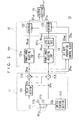
- FIG. 2 shows a preferred configuration of an encoding apparatus 10.
- An input image signal DVin is supplied to a toggle terminal 111a of a signal switch section 111.
- the signal switch section 111 is a constituent element of an arithmetic block 11.
- a terminal 111b of the signal switch section 111 is connected to a delay section 113.
- a terminal 111c thereof is connected to an adder 114 and a subtracter 115.
- the toggle terminal 111a is alternately connected to the terminal 111b or the terminal 111c by a switch control signal CSa from a signal switch control section 112.
- the signal switch control section 112 generates the switch control signal CSa.
- the switch control signal CSa allows the input image signal DVin that is a first frame image signal to be supplied to the terminal 111b of the signal switch section 111.
- the switch control signal CSa also allows the input image signal DVin that is a second frame image signal to be supplied to the terminal 111c.
- the delay section 113 receives the first frame image signal via the signal switch section 111 and delays it by one frame period. The delay section 113 then supplies the delayed signal as an image signal DVa to the adder 114 and the subtracter 115.
- the adder 114 receives the image signal DVa from the delay section 113 and an image signal DVb that is the second frame image signal via the signal switch section 111 and adds them at pixel positions corresponding to each other.
- the adder 114 also supplies a sum signal DVad thus obtained to a signal level adjusting section 121 in an encoding block 12 and a bit rate proportion control block 13.
- the subtracter 115 receives the image signal DVa and the image signal DVb and subtracts one from the other at pixel positions corresponding to each other.
- the subtracter 115 also supplies a difference signal DVsu thus obtained to the signal level adjusting section 121 and the bit rate proportion control block 13.
- the switch control signal CSa Because the connection of the toggle terminal 111a of the signal switch section 111 alternates between the terminal 111b and the terminal 111c on a per-frame basis by the switch control signal CSa, the sum signal DVad and the difference signal DVsu are sequentially generated for every two frames.
- a dynamic range adjusting part 121a of the signal level adjusting section 121 adjusts the level of the sum signal DV ad according to the dynamic range of the input of an encoder 122 connected to the dynamic range adjusting part 121a. For example, if the dynamic range of the input of the encoder 122 is equal to the dynamic range of the input image signal DVin, then the dynamic range of the sum signal DVad doubles that of the input image signal DVin. Therefore, the sum signal DVad level is adjusted to a factor of 0.5 in the dynamic range adjusting part 121a.
- the encoder 122 receives a sum signal DVadc having the thus adjusted signal level.
- a dynamic range adjusting part 121b adjusts the level of the difference signal DVsu according to the dynamic range of the input of an encoder 123, which will be described later, in the same way as the dynamic range adjusting part 121 a does. For example, if the dynamic range of the input of the encoder 123 is equal to the dynamic range of the input image signal DVin, then the dynamic range of the difference signal DVsu doubles that of the input image signal DVin. Therefore, the dynamic range adjusting part 121b adjusts the level of the difference signal DVsu to a factor of 0.5. A difference signal DVsuc having the thus adjusted signal level is supplied to a level shift part 121c.
- the level shift part 121c receives the difference signal DVsuc and offsets the level of the difference signal DVsuc according to the signal level of the input of the encoder 123 connected to the level shift part 121c.
- the difference signal DVsu results from the subtraction of one of the image signal DVb and the image signal DVa from the other.
- the difference signal DVsu has a " ⁇ L" signal level range.
- the signal level range of the offset difference signal DVsus can be made equal to that of the input image signal After the difference signal DVsuc is thus offset by adding the offset value H to it, the offset difference signal DVsus is supplied to the encoder 123.
- the encoders 122 and 123 make an adjustment of encoding bit rates for encoding the sum and difference signals, based on control signals from the bit rate proportion control block 13, which will be described later.
- a commonly applied encoding algorithm or an original encoding algorithm may be used.
- the encoder 122 encodes the sum signal DVadc, using an encoding bit rate which is set, based on a control signal CRad from the bit rate proportion control block 13, thereby generating an encoded signal DTad.
- a commonly applied encoding method such as, for example, DV and Motion-JPEG 2000 may be used.
- An encoding method by a completely original algorithm may be also performed.
- the encoded signal DTad generated by the encoder 122 is supplied to an output section 15.
- the encoder 123 encodes the difference signal DVsus, using an encoding bit rate which is set, based on a control signal CRsu from the bit rate proportion control block 13, thereby generating an encoded signal DTsu.
- the encoder 123 should carry out encoding in the same manner as the encoder 122 does.
- the encoded signal DTsu thus generated by the encoder 123 is also supplied to the output section 15.
- the bit rate proportion control block 13 determines the proportion of the encoding bit rates for one encoded signal DTad which is generated by the encoder 122 and the other encoded signal DTsu which is generated by the encoder 123, based on the sum signal and the difference signal to be encoded in the encoding bock 12.
- the control block 13 generates the control signal CRad to control the encoding operation such that the sum signal is encoded by the encoding bit rate proportion determined for the sum signal and supplies the control signal CRad to the encoder 122.
- control block 13 generates the control signal CRsu to control the encoding operation such that the difference signal is encoded by the encoding bit rate proportion determined for the difference signal and supplies the control signal CRsu to the encoder 123.
- the control signals CRad and CRsu are generated so that a higher encoding bit rate is assigned to the signal containing more information.
- the signal When the sum signal and the difference signal contains more information, the signal has greater signal level variation and wider signal level distribution.
- the encoded signal also contains more data.
- the control signals CRad and CRsu are generated so that a higher encoding bit rate is assigned to the signal containing more information.
- FIG. 3 shows a preferred configuration of the bit rate proportion control block 13 using signal level variation to judges whether or not the signal contains more information.
- a blocking circuit 131 decomposes the sum signal DVad into blocks and supplies the image signal components of the blocks to a deviation calculating circuit 132.
- the sum signal VDad is divided into small blocks consisting of eight horizontal pixels by eight vertical pixels.
- the image signal components of the blocks are supplied to the deviation calculating circuit 132.
- the deviation calculating circuit 132 calculates a value of standard deviation of each block using the signal levels of the pixels constituting the block. Then, using the calculated standard deviation values of all the blocks, the deviation calculating circuit 132 calculates average standard deviation SDad for one screen and supplies the calculated SDad to a proportion determining circuit 135.
- a blocking circuit 133 decomposes the difference signal DVsu into blocks as the blocking circuit 131 does and supplies the image signal components of the blocks to a deviation calculating circuit 134.
- the deviation calculating circuit 134 calculates average standard deviation SDsu in the same manner as the deviation calculating circuit 132 does and supplies the calculated SDsu to the proportion determining circuit 135.
- the proportion determining circuit 135 determines as the encoding bit rate proportion a ratio between the average standard deviation SDad calculated by the deviation calculating circuit 132 and the average standard deviation SDsu calculated by the deviation calculating circuit 134. Then, the proportion determining circuit 135 generates the control signals CRad and CRsu, based on the determined proportion. The proportion determining circuit 135 also supplies the control signal CRad to the encoder 122 and the control signal CRsu to the encoder 123.
- FIG. 4 shows another preferred configuration of the bit rate proportion control block 13' for generating the control signals CRad and CRsu, based on the data quantities of the pre-encoded signals.
- An encoder 136 encodes the sum signal DVad and supplies the thus encoded signal EVad to a data quantity determining circuit 137.
- the data quantity determining circuit 137 determines the data quantity of the encoded signal EVad and supplies a data quantity signal VDad indicating a result of the determination to a proportion determining circuit 140.
- An encoder 138 encodes the difference signal DVsu and supplies thus encoded signal EVsu to a data quantity determining circuit 139.
- the data quantity determining circuit 139 determines the data quantity of the encoded signal EVsu.
- the data quantity determining circuit 139 also supplies a data quantity signal VDsu indicating a result of determination to the proportion determining circuit 140.
- the proportion determining circuit 140 determines as the encoding bit rate proportion a ratio between the data quantities of both the encoded signals, based on the data quantity signal VDad from the data quantity determining circuit 137 and the data quantity signal VDsu from the data quantity determining circuit 139. Then, the proportion determining circuit 140 generates the control signals CRad and CRsu, based on the determined proportion, and supplies the control signal CRad to the encoder 122 and the control signal CRsu to the encoder 123.
- bit rate proportion control blocks 13 and 13' have determined the encoding bit rate proportion, using the sum signal DVad and the difference signal DVsu, these blocks may determine the encoding bit rate proportion in the same manner as described above, using the sum signal DVadc and the difference signal Dvsus which have the adjusted signal levels, respectively.
- bit rate proportion control blocks 13 and 13' may determine the encoding bit rate proportion, based on the sum and difference signals from the current encoding unit to a predetermined encoding unit subsequent to the current one. They may change over between the encoding bit rate proportion whenever a predetermined number of encoding units is finished.
- the output section 15 shown in FIG. 2 generates an output signal DTout, using the encoded signal DTad and the encoded signal DTsu.
- further processing such as adding error detection and correction codes, formatting in accordance with the recording medium or transmission protocol, and bit streaming may be performed, if necessary.
- the output signal DTout is generated. Different output signals may be generated from the encoded signal DTad and from the encoded signal DTsu separately.
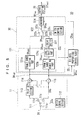
- Fig. 5 shows a preferred configuration of a decoding apparatus 20 for decoding the encoded signal received from the encoding apparatus 10.
- An input section 211 in a decoding block 21 receives as an input signal DTin the reproduction signal reproduced from a recording medium or a received signal distributed through a wired or wireless channel. This input signal DTin is equivalent to the output signal DTout output from the encoding apparatus 10.
- the input section 211 decomposes the input signal DTin into an encoded signal DTad and an encoded signal DTsu and supplies the encoded signal DTad to a decoder 212 and the encoded signal DTsu to a decoder 213.
- the input section 211 may decompose the input signal into the encoded signal DTad and the encoded signal DTsu, using header information or parsing the encoded signals.
- the input section 211 may carry out error detection and correction for the encoded signal DTad and the encoded signal DTsu.
- the decoder 212 decodes the encoded signal DTad into the sum signal DVadc.
- the sum signal DVadc is then supplied to an adder 221 and a subtracter 222 in an arithmetic block 22.
- This decoding corresponds to the encoding performed by the encoder 122.
- decoding corresponding to this encoding allows the signal before being encoded to be reproduced.
- the decoder 213 decodes the encoded signal DTsu into the difference signal DVsus.
- the difference signal DVsus is then supplied to a reverse level shift part 214a in a signal level adjusting section 214. This decoding corresponds to the encoding performed by the encoder 123 shown in FIG. 2.
- the reverse level shift part 214a offsets the level of difference signal DVsus in the reverse direction to cancel the offset given by the level shift section 121c shown in FIG. 2, thus reproducing the difference signal DVsuc before being offset.
- This difference signal DVsuc is supplied to the adder 221 and the subtracter 222.
- the sum signal DVadc to be supplied from the decoder 212 to the arithmetic block 22 and the difference signal DVsuc to be supplied from the reverse level shift part 214a to the arithmetic block 22 are timed.
- the adder 221 in the arithmetic block 22 then adds the sum signal DVadc supplied from the decoder 212 and the difference signal DVsuc supplied from the reverse level shift part 214a at their corresponding pixel positions.
- An image signal DVc obtained by this addition is supplied to the terminal 232a of a signal switch section 232 in an output block 23.
- the subtracter 222 subtracts any one of the sum signal DVadc and the difference signal DVsuc from the other at their corresponding pixel positions.
- An image signal DVd obtained by this subtraction is supplied to a delay section 231 in the output block 23.
- the delay section 231 in the output block 23 delays the image signal DVd by one frame period and supplies this delayed signal as an image signal DVe to the terminal 232b of the signal switch section 232.
- the signal switch section 232 receives a switch control signal CSb from a signal switch control section 233 and switches the connection of its toggle terminal 232c alternating between the terminal 232a and the terminal 232b, based on the switch control signal CSb. The signal selected by this signal switch section 232 is then output as an output image signal DVout.
- the signal switch control section 233 generates and supplies the switch control signal CSb to the signal switch section 232.
- the switch control signal CSb causes the toggle terminal 232c of the signal switch section 232 to connect to the terminal 232a at the timing when the image signal DVc is supplied from the adder 221 to the terminal 232a of the signal switch section 232.
- the switch control signal CSb also causes the toggle terminal 232c of the signal switch section 232 to connect to the terminal 232b at the timing when the image signal DVe is supplied from the delay section 231 to the terminal 232b of the signal switch section 232.
- the image signal DVd is delayed by one frame period through the delay section 231 and output as the image signal DVe, and the image signal DVc and the image signal DVe are alternately selected by the switch operation of the signal switch section 232.
- the image signals of two frames can be output in a predetermined frame sequence and the output image signal DVout equivalent to the input image signal DVin which has been input to the encoding apparatus 10 can be obtained.
- FIG. 6 is a diagram for showing the operations of the encoding apparatus 10. Note that FIG. 6 and FIGS. 7, 10 and 11, which will be described later, are intended to explain the operations of sequentially generating the signals in the encoding apparatus and the decoding apparatus, wherein no consideration is taken for actual timing of generating the signals.
- the signal switch section 111 operates such that the DVin signal is passed to the delay section 113 if it is a first frame signal and passed to the subtracter 115 if it is a second frame signal.
- the first frame signal "O1" synchronizes with the second frame signal "E1," as is shown in step B.
- FIG. 7 is a diagram for showing the operations of the decoding apparatus 20.
- the input signal DTin comprising the encoded signal DTad and the encoded signal DTsu as shown in step A is input to the decoding apparatus 20.
- the reverse level shift part 214a subtracts the offset value H added by the level shift part 121 c in the encoding apparatus 10 from the difference signal DVsus reproduced by the decoder 213.
- output image signals DVout can be output sequentially.
- the output image signals DVout are equivalent to the input image signals DVin used in a generation of the input signals DTin.
- the dynamic range adjusting parts 121a and 121b in the encoding apparatus 10 adjust the levels of the sum signal and the difference signal to reduce by a factor of two.
- the image signals having a proper signal level can be obtained simply by addition and subtraction of the sum and difference signals in the arithmetic block 22 in the decoding apparatus 20.
- this embodiment makes the decoding apparatus configuration simple.
- the encoders 122 and 123 have the same dynamic range of input as those of the sum signal DVad and the difference signal DVsu so that the dynamic range adjustment can not be performed.
- the decoding apparatus 20 should include dynamic range adjusting parts for adjusting the dynamic ranges of the sum signal DVadc and the difference signal DVsuc to reduce by a factor of two in the signal level adjusting section 214. This allows the image signals having a proper signal level to be obtained.
- the encoding apparatus 10 performs encoding on a two-frame basis as explained hereinbefore. If the encoding apparatus provides the same image quality as the one obtained by the conventional intra-frame encoding, the bit rate of the output signal DTout can be made lower. If it provides the same bit rate as the conventional one, higher image quality can be obtained.
- encoded signals are generated on a two-frame basis, the frames of encoded output signals DTout can be edited with higher precision than in the case of long-GOP frames.
- Simple configurations for encoding and decoding are possible because of no need for heavy load processing such as detecting motion vectors and motion compensation.
- double encoders and decoders have been used, one for the sum signal, the other for the difference signal.
- This invention is not limited to this.
- a single encoder and a single decoder may be alternately used. In this way, the encoding apparatus configuration and the decoding apparatus configuration can be made simpler.
- FIG. 8 shows a configuration of another preferred encoding apparatus 30 in which a single encoder is used for both the sum signal and the difference signal.
- like reference numbers referred to components shown in FIG. 2 refer to like components in this preferred embodiment and thus, their explanation is omitted.
- the sum signal DVadc output from a dynamic range adjusting part 121a in the encoding block 32 is supplied to the terminal 322a of a signal switch section 322.
- the difference signal DVsus output from the level shift part 121c is supplied to a delay section 321.
- the delay section 321 delays the difference signal DVsus by one frame period and supplies a delayed difference signal DVsud to the terminal 322b of the signal switch section 322.
- the signal switch section 322 switches the connection of its toggle terminal 322c between the terminal 322a and the terminal 322b, based on a switch control signal CSc received from a signal switch control section 323, and selects the sum signal DVadc or the difference signal DVsud.
- the signal selected by the signal switch section 322 is supplied as a selected signal DVas to an encoder 324.
- the signal switch control section 323 generates the switch control signal CSc to be supplied to the toggle terminal 322c and supplies it to the signal switch section 322.
- the switch control signal CSc serves as alternative selection of the sum signal DVadc supplied from the dynamic range adjusting part 121a to the terminal 322a of the signal switch section 322 and the difference signal DVsud supplied from the delay section 321 to the terminal 322b of the signal switch section 322.
- the encoder 324 encodes the selected signal DVas into an encoded signal DTas and then supplies it to an output section 35.
- the encoded signal DTas is generated at an encoding bit rate based on a control signal CRas supplied from a bit rate proportion control block 33, which will be described later.
- a commonly applied encoding method or encoding by original algorithm may be carried out, as is the case for the encoders 122 and 123 of the above-described embodiment.
- the encoding apparatus 30 use the encoder 324 capable of encoding both the sum and difference signals within the period of one encoding unit in order to complete real-time encoding.
- the bit rate proportion control block 33 also determines a proportion of the encoding bit rates based on the sum signal and the difference signal. The proportion is set between one encoded signal obtained by encoding the sum signal DVadc and the other encoded signal obtained by encoding the difference signal DVsud. Besides, the control block 33 judges which of the sum signal DVadc and the difference signal DVsud is supplied as the selected signal DVas to the encoder 324, based on the switch control signal CSc. The control block 33 then supplies the encoder 324 with the control signal CRas appropriate for the signal to be supplied to the encoder 324.
- the control block 33 supplies the encoder 324 with a control signal CRad as the control signal CRas.
- the control signal CRad is equivalent to the control signal CRad generated by the foregoing bit rate proportion control blocks 13 and 13'.
- the control block 33 supplies the encoder 324 with a control signal CRsu as the control signal CRas.
- the control signal CRsu is equivalent to the control signal CRsu generated by the foregoing bit rate proportion control blocks 13 and 13'.
- the output section 35 generates the output signal DTout from the encoded signal DTas.
- the output section 35 may carry out further processing such as adding error detection and correction codes, formatting in accordance with the recording medium or transmission protocol, and bit streaming, if appropriate, and generate the output signal DTout.
- FIG. 9 shows a configuration of another preferred decoding apparatus 40 which decodes the signal output from the encoding apparatus 30.
- like reference numbers referred to components shown in FIG. 5 refer to like components in this preferred embodiment and thus, their explanation is omitted.
- An input section 411 in the decoding block 41 extracts the encoded signal DTas from the input signal DTin and supplies the signal DTas to a decoder 412.
- the input section 411 may carry out error detection and correction for the encoded signal DTas.
- the decoder 412 decodes the encoded signal DTas.
- the selected signal DVas obtained by this decoding is supplied to a toggle terminal 413a of a signal switch section 413.
- the decoder 412 generates and supplies a switch control signal CSd to the signal switch section 413.
- the switch control signal CSd causes the connection of the toggle terminal 413a of the signal switch section 413 to switch to the terminal 413b or terminal 413c in coincidence with the boundary between the sum signal DVadc and the difference signal DVsud based on the selected signal DVas.
- the boundary between the sum signal DVadc and the difference signal DVsud can be detected using header information, as is the case for the foregoing input section 211, or based on the number of blocks on the basis of EOB codes or the number decoded blocks and the like. Based on the result of the detection, the decoder 412 generates the switch control signal CSd.
- the signal switch section 413 switches the connection of the toggle terminal 413a to the terminal 413b or terminal 413c, based on the switch control signal CSd.
- the signal switch section 413 also supplies the sum signal DVadc component of the selected signal DVas to a delay section 414 and the difference signal DVsud component of the selected signal DVas to a reverse level shift section 415.
- the delay section 414 delays the sum signal DVadc by one frame period and supplies a delayed sum signal DVadd to the adder 221 and the subtracter 222.
- the reverse level shift section 415 in the signal level adjusting section offsets the level of the difference signal DVsud in the reverse direction to cancel the offset given by the level shift part 121c.
- the reverse level shift section 415 also supplies the thus reproduced difference signal DVsuc having the signal level before being offset to the adder 221 and the subtracter 222.
- Integrating the delay section 414 into the circuitry allows the sum signal DVadc and the difference signal DVsuc to be synchronized when the signals are supplied to the adder 221 and the subtracter 222.
- the adder 221 adds the sum signal DVadc and the difference signal DVsuc at the corresponding pixel positions, thus reproducing the image signal DVc.
- the subtracter 222 subtracts any one of the sum signal DVadc and the difference signal DVsuc from the other at the corresponding pixel positions, thus reproducing the image signal DVd.
- a delay section 231 receives and delays the image signal DVd by one frame period and supplies a delayed image signal DVe to the terminal 232b of a signal switch section 232.
- the signal switch section 232 alternately selects and outputs the image signal DVc and the image signal DVe on a per-frame basis. This allows the output image signal DVout equivalent to the input image signal DVin which has been input to the decoding apparatus 30 to be obtained.
- FIG. 10 is a diagram for explaining the operations of the encoding apparatus 30.
- the signal switch section 111 operates such that the DVin signal is passed to the delay section 113 if it is a first frame signal and passed to the subtracter 115 if it is a second frame signal. Consequently, in the image signal DVa output from the delay section 113, the first frame signal "O1" synchronizes with the second frame signal "E1," as shown in step B.
- the delay section 321 delays the difference signal DVsus by one frame period, thus generating a delayed difference signal DVsud as shown in step H.
- the signal switch section 322 alternatively selects the sum signal DVadc and the difference signal DVsud per encoding unit and supplies the selected signal DVas as shown in step I to the encoder.
- the encoder 324 encodes the selected signal DVas into the encoded signal DTas as shown in step J according to a bit rate proportion which is set, based on the sub signal DVad and the difference signal DVsu.
- FIG. 11 explains the operations of the decoding apparatus 40.
- the input signal DTin including the encoded signals DTas is input to the decoding apparatus 40 as shown in step A.
- the signal switch section 413 extracts the sum signal part from the selected signal DVas sequence and supplies the extracted sum signal DVadc to the delay section 414.
- the delay section 414 delays the sum signal DVadc by one frame period and supplies the delayed sum signal DVadd which is shown in step D to the adder 211.
- output image signals DVout can be output sequentially.
- the output image signals DVout are equivalent to the input image signals DVin which have been used for encoding the input signals DTin.
- the encoding apparatus 30 encodes both the sum signal DVadc and the difference signal DVsud with the single encoder 324.
- the decoding apparatus 40 decodes the encoded signals into the sum signal DVadc and the difference signal DVsud with the single decoder 412.
- the encoding apparatus and the decoding apparatus can be fabricated at lower cost, dispensing with double encoders and decoders, one for the sum signal and the other for the difference signal.
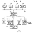
- the computer includes a CPU (Central Processing Unit) 501 to which an ROM 502, an RAM 503, a hard disk drive 504, and I/O interface 505 are connected via a bus 520.
- a CPU Central Processing Unit
- I/O interface 505 To the I/O interface 505, an input unit 511, a recording medium drive 512, a communication unit 513, a signal input unit, and a signal output unit 515 are connected.
- the command is supplied to the CPU 501 via the I/O interface 505.
- the CPU 501 executes a program stored in the ROM 502, the RAM 503, or the hard disk drive 504 and performs a process in response to the supplied command.
- Programs for causing the computer to carry out the same processing tasks as the foregoing encoding apparatus and decoding apparatus do are stored beforehand into the ROM 502, the RAM 503, or the hard disk drive 504.
- the input image signal DVin input to the signal input unit 514 is encoded and output as the output signal DTout from the signal output unit 515.
- the input signal DTin input to the signal input unit 514 is decoded and output as the output signal DVout from the signal output unit 515.
- the programs be stored on a removable recording medium to be mounted on the computer.
- the programs are stored onto the recording medium or the programs are read from the recording medium by the recording medium drive 51 and executed on the computer.
- the programs may also be preferable that the programs be transmitted or received through a transmission channel by the communication unit 513. In this case, the programs thus received are executed on the computer.
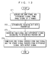
- FIG. 13 is a flowchart explaining the encoding operation.
- step ST1 from the input image signal DVin input through the signal input unit 514, a sum signal of the frames and a frame-to-frame difference signal are generated per pixel using the image signal of two frames that are an encoding unit. Then, the process proceeds to step ST2.
- step ST2 the proportion of the encoding bit rates for one encoded signal generated by encoding the sum signal and the other encoded signal generated by encoding the difference signal is determined, based on the sum signal and the difference signal. For example, as described above, the sum signal and the difference signal are divided into blocks, respectively, and, from the standard deviation values of the blocks, average standard deviation for one screen is calculated for the sum signal and the difference signal, respectively. A ratio between the average standard deviation obtained for the sum signal and the average standard deviation obtained for the difference signal is determined as the encoding bit rate proportion. Alternatively, the encoding bit rate proportion may be determined by a ratio between the data quantity of one encoded signal obtained by pre-encoding the sum signal and the data quantity of the other encoded signal obtained by pre-encoding the difference signal.
- step ST3 encoding the sum signal and the difference signal is performed according to the encoding bit rate proportion determined in step ST2.
- a commonly applied encoding method or encoding by an original algorithm may be performed, provided the encoding bit rates can be adjusted.
- step ST4 one encoded signal obtained by encoding the sum signal and the other encoded signal obtained by encoding the difference signal are combined to generate an output signal.
- the output signal thus generated is then output from the signal output unit 515.
- FIG. 14 is a flowchart explaining the decoding operation for decoding the signals generated by the encoding apparatuses shown in FIG. 2 and FIG. 8 and/or the process shown in the flowchart of FIG. 13.
- step ST11 the input signal DTin input through the signal input unit 514 is decoded into the sum signal and the difference signal. Then, the process proceeds to step ST12.
- step ST11 a commonly applied decoding method or decoding by an original algorithm, which correspond to the encoding method or algorithm may be performed.
- step ST12 arithmetic processing is performed using the sum signal and the difference signal, thus generating the image signal of two frames. Then, the process proceeds to step ST13.
- step ST13 the generated image signals of two frames are sequenced along the time axis and output as the output image signal DVout from the signal output unit 515.
- second field sum signal and difference signal following first field sum signal and difference signal will be supplied to the encoders 122 and 123, the encoder 324, or the encoders 136 and 137.
- assembling the first and second field image signals into a frame is performed before being supplied to the encoders 122 and 123 or the encoders 136 and 137.
- the sum signal and difference signal of one frame can be supplied to the encoders 122 and 123 or the encoders 136 and 137. This allows an output signal DTout equal to that of the progressive scan images to be obtained even when the input image signals DVin are interlace scan images.
Landscapes
- Engineering & Computer Science (AREA)
- Multimedia (AREA)
- Signal Processing (AREA)
- Compression Or Coding Systems Of Tv Signals (AREA)
- Compression, Expansion, Code Conversion, And Decoders (AREA)
Applications Claiming Priority (2)
| Application Number | Priority Date | Filing Date | Title |
|---|---|---|---|
| JP2002267122 | 2002-09-12 | ||
| JP2002267122A JP2004104694A (ja) | 2002-09-12 | 2002-09-12 | 符号化装置と符号化方法と符号化プログラムおよび復号化装置と復号化方法と復号化プログラム |
Publications (1)
| Publication Number | Publication Date |
|---|---|
| EP1398971A1 true EP1398971A1 (de) | 2004-03-17 |
Family
ID=31884798
Family Applications (1)
| Application Number | Title | Priority Date | Filing Date |
|---|---|---|---|
| EP20030255533 Withdrawn EP1398971A1 (de) | 2002-09-12 | 2003-09-04 | Videokodierung und -dekodierung |
Country Status (3)
| Country | Link |
|---|---|
| US (1) | US20040062311A1 (de) |
| EP (1) | EP1398971A1 (de) |
| JP (1) | JP2004104694A (de) |
Cited By (1)
| Publication number | Priority date | Publication date | Assignee | Title |
|---|---|---|---|---|
| WO2006084419A1 (en) * | 2005-02-08 | 2006-08-17 | Hongkong Applied Science And Technology Research Institute Co., Ltd. | Method for reducing bit rate requirements for encoding multimedia data |
Families Citing this family (5)
| Publication number | Priority date | Publication date | Assignee | Title |
|---|---|---|---|---|
| CN101133649B (zh) * | 2005-12-07 | 2010-08-25 | 索尼株式会社 | 编码装置、编码方法以及解码装置、解码方法 |
| JPWO2007066710A1 (ja) * | 2005-12-07 | 2009-05-21 | ソニー株式会社 | 符号化装置、符号化方法および符号化プログラム、ならびに、復号装置、復号方法および復号プログラム |
| JP4265642B2 (ja) | 2006-10-16 | 2009-05-20 | ソニー株式会社 | 情報処理装置および方法、記録媒体、並びにプログラム |
| JPWO2008093698A1 (ja) * | 2007-01-31 | 2010-05-20 | ソニー株式会社 | 情報処理装置および方法 |
| RU2479937C2 (ru) | 2007-03-30 | 2013-04-20 | Сони Корпорейшн | Устройство и способ обработки информации |
Citations (3)
| Publication number | Priority date | Publication date | Assignee | Title |
|---|---|---|---|---|
| US5309232A (en) * | 1992-02-07 | 1994-05-03 | At&T Bell Laboratories | Dynamic bit allocation for three-dimensional subband video coding |
| JPH06292179A (ja) * | 1993-04-01 | 1994-10-18 | Matsushita Electric Ind Co Ltd | 直交変換符号化装置および直交変換復号化装置 |
| EP0679032A2 (de) * | 1994-04-20 | 1995-10-25 | Oki Electric Industry Co., Ltd. | Gerät und Verfahren zur Kodierung und Dekodierung von Bildern unter Verwendung einer Kantensynthese und einer Wavelet-Rücktransformation |
Family Cites Families (5)
| Publication number | Priority date | Publication date | Assignee | Title |
|---|---|---|---|---|
| US5134475A (en) * | 1990-12-11 | 1992-07-28 | At&T Bell Laboratories | Adaptive leak hdtv encoder |
| US5313298A (en) * | 1992-03-05 | 1994-05-17 | Rubin, Bednarek And Associates, Inc. | Video companding method and system |
| US5592302A (en) * | 1992-03-23 | 1997-01-07 | Canon Kabushiki Kaisha | Coding method for coding pixel blocks and apparatus therefor |
| JP3348310B2 (ja) * | 1992-09-28 | 2002-11-20 | ソニー株式会社 | 動画像符号化方法および動画像符号化装置 |
| CA2163178C (en) * | 1994-11-18 | 1999-11-16 | Norio Suzuki | Tv signal codec with amplitude limitation and a shift |
-
2002
- 2002-09-12 JP JP2002267122A patent/JP2004104694A/ja active Pending
-
2003
- 2003-09-04 EP EP20030255533 patent/EP1398971A1/de not_active Withdrawn
- 2003-09-10 US US10/659,231 patent/US20040062311A1/en not_active Abandoned
Patent Citations (3)
| Publication number | Priority date | Publication date | Assignee | Title |
|---|---|---|---|---|
| US5309232A (en) * | 1992-02-07 | 1994-05-03 | At&T Bell Laboratories | Dynamic bit allocation for three-dimensional subband video coding |
| JPH06292179A (ja) * | 1993-04-01 | 1994-10-18 | Matsushita Electric Ind Co Ltd | 直交変換符号化装置および直交変換復号化装置 |
| EP0679032A2 (de) * | 1994-04-20 | 1995-10-25 | Oki Electric Industry Co., Ltd. | Gerät und Verfahren zur Kodierung und Dekodierung von Bildern unter Verwendung einer Kantensynthese und einer Wavelet-Rücktransformation |
Non-Patent Citations (6)
| Title |
|---|
| ANONYMOUS: "Wavelets", WEB PAGE, 26 February 2001 (2001-02-26), XP002263155, Retrieved from the Internet <URL:http://www.ltcconline.net/greenl/courses/203/MatricesApps/wavelets.htm> [retrieved on 20031127] * |
| KARLSSON, G., VETTERLI, M.: "Sub-band coding of video signals for packet-switched networks", PROCEEDINGS OF SPIE - THE INTERNATIONAL SOCIETY FOR OPTICAL ENGINEERING - VISUAL COMMUNICATIONS AND IMAGE PROCESSING II, 27 October 1987 (1987-10-27) - 29 October 1987 (1987-10-29), Cambridge, US, pages 446 - 456, XP008024827 * |
| OHM J R: "ADVANCED PACKET-VIDEO CODING BASED ON LAYERED VQ AND SBC TECHNIQUES", IEEE TRANSACTIONS ON CIRCUITS AND SYSTEMS FOR VIDEO TECHNOLOGY, IEEE INC. NEW YORK, US, vol. 3, no. 3, 1 June 1993 (1993-06-01), pages 208 - 221, XP000385794, ISSN: 1051-8215 * |
| OHM J-R: "THREE-DIMENSIONAL SUBBAND CODING WITH MOTION COMPENSATION", IEEE TRANSACTIONS ON IMAGE PROCESSING, IEEE INC. NEW YORK, US, vol. 3, no. 5, 1 September 1994 (1994-09-01), pages 559 - 571, XP000476832, ISSN: 1057-7149 * |
| PATENT ABSTRACTS OF JAPAN vol. 1995, no. 01 28 February 1995 (1995-02-28) * |
| SANDBERG, K.: "The Haar wavelet transform", WEB PAGE, 1 April 2000 (2000-04-01), XP002263156, Retrieved from the Internet <URL:http://amath.colorado.edu/courses/4720/2000Spr/Labs/Haar/haar.html> [retrieved on 20031127] * |
Cited By (1)
| Publication number | Priority date | Publication date | Assignee | Title |
|---|---|---|---|---|
| WO2006084419A1 (en) * | 2005-02-08 | 2006-08-17 | Hongkong Applied Science And Technology Research Institute Co., Ltd. | Method for reducing bit rate requirements for encoding multimedia data |
Also Published As
| Publication number | Publication date |
|---|---|
| US20040062311A1 (en) | 2004-04-01 |
| JP2004104694A (ja) | 2004-04-02 |
Similar Documents
| Publication | Publication Date | Title |
|---|---|---|
| US6516034B2 (en) | Stream processing apparatus and method | |
| CA2137266C (en) | Picture encoding method, picture encoding apparatus and picture recording medium | |
| JP3092610B2 (ja) | 動画像の復号化方法、該方法が記録されたコンピュータ読みとり可能な記録媒体、及び、動画像の復号化装置 | |
| EP1206874B1 (de) | Transkodierung für konsumsettopspeicherungsanwendungen | |
| US5587806A (en) | Apparatus for separately recording input coded video signal and important data generated therefrom | |
| KR19990072968A (ko) | 화상신호처리시스템,디코더,화상신호처리방법,및디코딩방법 | |
| JPH04358486A (ja) | 高能率符号化信号処理装置 | |
| JPH089319A (ja) | ディジタルビデオ信号の記録方法、記録装置及び再生装置 | |
| WO1998025407A1 (en) | Method and apparatus for transmitting, encoding and decoding video signal and recording/reproducing method of optical disc | |
| KR20020030100A (ko) | 화상 부호화 장치 및 화상 부호화 방법 | |
| JP3348612B2 (ja) | ブロック間予測符号化装置、ブロック間予測復号化装置、ブロック間予測符号化方法、ブロック間予測復号化方法、及びブロック間予測符号化復号化装置 | |
| US7286715B2 (en) | Quantization apparatus, quantization method, quantization program, and recording medium | |
| JP3852366B2 (ja) | 符号化装置および方法、復号装置および方法、並びにプログラム | |
| EP1398971A1 (de) | Videokodierung und -dekodierung | |
| JPH0937243A (ja) | 動画像符号化装置及び復号装置 | |
| JP3609571B2 (ja) | 画像再生装置 | |
| EP0616467B1 (de) | Gerät zur Aufzeichnung eines Videosignals | |
| CN100531377C (zh) | 图像处理设备以及图像处理方法 | |
| US20040131116A1 (en) | Image processing apparatus, image processing method, image processing program, and recording medium | |
| JP5471328B2 (ja) | 動画像再生装置及び動画像再生方法並びにプログラム | |
| JP2004023670A (ja) | 画像符号化装置および同方式 | |
| JP3703088B2 (ja) | 拡張画像符号化装置及び拡張画像復号化装置 | |
| JP3946177B2 (ja) | 動画像符号化装置及び復号装置 | |
| JPH09130744A (ja) | デジタル記録再生装置 | |
| JP2006054760A (ja) | 画像処理装置及び画像処理方法 |
Legal Events
| Date | Code | Title | Description |
|---|---|---|---|
| PUAI | Public reference made under article 153(3) epc to a published international application that has entered the european phase |
Free format text: ORIGINAL CODE: 0009012 |
|
| AK | Designated contracting states |
Kind code of ref document: A1 Designated state(s): AT BE BG CH CY CZ DE DK EE ES FI FR GB GR HU IE IT LI LU MC NL PT RO SE SI SK TR |
|
| AX | Request for extension of the european patent |
Extension state: AL LT LV MK |
|
| 17P | Request for examination filed |
Effective date: 20040902 |
|
| AKX | Designation fees paid |
Designated state(s): DE FR GB |
|
| STAA | Information on the status of an ep patent application or granted ep patent |
Free format text: STATUS: THE APPLICATION HAS BEEN WITHDRAWN |
|
| 18W | Application withdrawn |
Effective date: 20080211 |