EP1399048B1 - Appareil sanitaire - Google Patents
Appareil sanitaire Download PDFInfo
- Publication number
- EP1399048B1 EP1399048B1 EP01986429A EP01986429A EP1399048B1 EP 1399048 B1 EP1399048 B1 EP 1399048B1 EP 01986429 A EP01986429 A EP 01986429A EP 01986429 A EP01986429 A EP 01986429A EP 1399048 B1 EP1399048 B1 EP 1399048B1
- Authority
- EP
- European Patent Office
- Prior art keywords
- plate
- sanitary
- light
- bath tub
- shower cubicle
- Prior art date
- Legal status (The legal status is an assumption and is not a legal conclusion. Google has not performed a legal analysis and makes no representation as to the accuracy of the status listed.)
- Expired - Lifetime
Links
Images
Classifications
-
- F—MECHANICAL ENGINEERING; LIGHTING; HEATING; WEAPONS; BLASTING
- F21—LIGHTING
- F21V—FUNCTIONAL FEATURES OR DETAILS OF LIGHTING DEVICES OR SYSTEMS THEREOF; STRUCTURAL COMBINATIONS OF LIGHTING DEVICES WITH OTHER ARTICLES, NOT OTHERWISE PROVIDED FOR
- F21V33/00—Structural combinations of lighting devices with other articles, not otherwise provided for
- F21V33/0004—Personal or domestic articles
- F21V33/004—Sanitary equipment, e.g. mirrors, showers, toilet seats or paper dispensers
-
- A—HUMAN NECESSITIES
- A47—FURNITURE; DOMESTIC ARTICLES OR APPLIANCES; COFFEE MILLS; SPICE MILLS; SUCTION CLEANERS IN GENERAL
- A47B—TABLES; DESKS; OFFICE FURNITURE; CABINETS; DRAWERS; GENERAL DETAILS OF FURNITURE
- A47B97/00—Furniture or accessories for furniture, not provided for in other groups of this subclass
-
- A—HUMAN NECESSITIES
- A47—FURNITURE; DOMESTIC ARTICLES OR APPLIANCES; COFFEE MILLS; SPICE MILLS; SUCTION CLEANERS IN GENERAL
- A47K—SANITARY EQUIPMENT; ACCESSORIES THEREFOR, e.g. TOILET ACCESSORIES
- A47K3/00—Baths; Showers; Appurtenances therefor
- A47K3/02—Baths
-
- A—HUMAN NECESSITIES
- A47—FURNITURE; DOMESTIC ARTICLES OR APPLIANCES; COFFEE MILLS; SPICE MILLS; SUCTION CLEANERS IN GENERAL
- A47K—SANITARY EQUIPMENT; ACCESSORIES THEREFOR, e.g. TOILET ACCESSORIES
- A47K3/00—Baths; Showers; Appurtenances therefor
- A47K3/28—Showers or bathing douches
- A47K3/40—Pans or trays
-
- E—FIXED CONSTRUCTIONS
- E04—BUILDING
- E04H—BUILDINGS OR LIKE STRUCTURES FOR PARTICULAR PURPOSES; SWIMMING OR SPLASH BATHS OR POOLS; MASTS; FENCING; TENTS OR CANOPIES, IN GENERAL
- E04H1/00—Buildings or groups of buildings for dwelling or office purposes; General layout, e.g. modular co-ordination or staggered storeys
- E04H1/12—Small buildings or other erections for limited occupation, erected in the open air or arranged in buildings, e.g. kiosks, waiting shelters for bus stops or for filling stations, roofs for railway platforms, watchmen's huts or dressing cubicles
- E04H1/1205—Small buildings erected in the open air
- E04H1/1211—Waiting shelters for bus stops
-
- F—MECHANICAL ENGINEERING; LIGHTING; HEATING; WEAPONS; BLASTING
- F21—LIGHTING
- F21V—FUNCTIONAL FEATURES OR DETAILS OF LIGHTING DEVICES OR SYSTEMS THEREOF; STRUCTURAL COMBINATIONS OF LIGHTING DEVICES WITH OTHER ARTICLES, NOT OTHERWISE PROVIDED FOR
- F21V23/00—Arrangement of electric circuit elements in or on lighting devices
-
- F—MECHANICAL ENGINEERING; LIGHTING; HEATING; WEAPONS; BLASTING
- F21—LIGHTING
- F21V—FUNCTIONAL FEATURES OR DETAILS OF LIGHTING DEVICES OR SYSTEMS THEREOF; STRUCTURAL COMBINATIONS OF LIGHTING DEVICES WITH OTHER ARTICLES, NOT OTHERWISE PROVIDED FOR
- F21V23/00—Arrangement of electric circuit elements in or on lighting devices
- F21V23/04—Arrangement of electric circuit elements in or on lighting devices the elements being switches
- F21V23/0442—Arrangement of electric circuit elements in or on lighting devices the elements being switches activated by means of a sensor, e.g. motion or photodetectors
-
- F—MECHANICAL ENGINEERING; LIGHTING; HEATING; WEAPONS; BLASTING
- F21—LIGHTING
- F21V—FUNCTIONAL FEATURES OR DETAILS OF LIGHTING DEVICES OR SYSTEMS THEREOF; STRUCTURAL COMBINATIONS OF LIGHTING DEVICES WITH OTHER ARTICLES, NOT OTHERWISE PROVIDED FOR
- F21V33/00—Structural combinations of lighting devices with other articles, not otherwise provided for
- F21V33/0004—Personal or domestic articles
- F21V33/0012—Furniture
-
- F—MECHANICAL ENGINEERING; LIGHTING; HEATING; WEAPONS; BLASTING
- F21—LIGHTING
- F21V—FUNCTIONAL FEATURES OR DETAILS OF LIGHTING DEVICES OR SYSTEMS THEREOF; STRUCTURAL COMBINATIONS OF LIGHTING DEVICES WITH OTHER ARTICLES, NOT OTHERWISE PROVIDED FOR
- F21V33/00—Structural combinations of lighting devices with other articles, not otherwise provided for
- F21V33/006—General building constructions or finishing work for buildings, e.g. roofs, gutters, stairs or floors; Garden equipment; Sunshades or parasols
-
- F—MECHANICAL ENGINEERING; LIGHTING; HEATING; WEAPONS; BLASTING
- F21—LIGHTING
- F21V—FUNCTIONAL FEATURES OR DETAILS OF LIGHTING DEVICES OR SYSTEMS THEREOF; STRUCTURAL COMBINATIONS OF LIGHTING DEVICES WITH OTHER ARTICLES, NOT OTHERWISE PROVIDED FOR
- F21V9/00—Elements for modifying spectral properties, polarisation or intensity of the light emitted, e.g. filters
- F21V9/08—Elements for modifying spectral properties, polarisation or intensity of the light emitted, e.g. filters for producing coloured light, e.g. monochromatic; for reducing intensity of light
-
- G—PHYSICS
- G02—OPTICS
- G02B—OPTICAL ELEMENTS, SYSTEMS OR APPARATUS
- G02B6/00—Light guides; Structural details of arrangements comprising light guides and other optical elements, e.g. couplings
- G02B6/0001—Light guides; Structural details of arrangements comprising light guides and other optical elements, e.g. couplings specially adapted for lighting devices or systems
- G02B6/0011—Light guides; Structural details of arrangements comprising light guides and other optical elements, e.g. couplings specially adapted for lighting devices or systems the light guides being planar or of plate-like form
- G02B6/0013—Means for improving the coupling-in of light from the light source into the light guide
- G02B6/0015—Means for improving the coupling-in of light from the light source into the light guide provided on the surface of the light guide or in the bulk of it
- G02B6/0018—Redirecting means on the surface of the light guide
-
- G—PHYSICS
- G02—OPTICS
- G02B—OPTICAL ELEMENTS, SYSTEMS OR APPARATUS
- G02B6/00—Light guides; Structural details of arrangements comprising light guides and other optical elements, e.g. couplings
- G02B6/0001—Light guides; Structural details of arrangements comprising light guides and other optical elements, e.g. couplings specially adapted for lighting devices or systems
- G02B6/0011—Light guides; Structural details of arrangements comprising light guides and other optical elements, e.g. couplings specially adapted for lighting devices or systems the light guides being planar or of plate-like form
- G02B6/0033—Means for improving the coupling-out of light from the light guide
- G02B6/0035—Means for improving the coupling-out of light from the light guide provided on the surface of the light guide or in the bulk of it
- G02B6/004—Scattering dots or dot-like elements, e.g. microbeads, scattering particles, nanoparticles
- G02B6/0043—Scattering dots or dot-like elements, e.g. microbeads, scattering particles, nanoparticles provided on the surface of the light guide
-
- G—PHYSICS
- G02—OPTICS
- G02B—OPTICAL ELEMENTS, SYSTEMS OR APPARATUS
- G02B6/00—Light guides; Structural details of arrangements comprising light guides and other optical elements, e.g. couplings
- G02B6/0001—Light guides; Structural details of arrangements comprising light guides and other optical elements, e.g. couplings specially adapted for lighting devices or systems
- G02B6/0011—Light guides; Structural details of arrangements comprising light guides and other optical elements, e.g. couplings specially adapted for lighting devices or systems the light guides being planar or of plate-like form
- G02B6/0066—Light guides; Structural details of arrangements comprising light guides and other optical elements, e.g. couplings specially adapted for lighting devices or systems the light guides being planar or of plate-like form characterised by the light source being coupled to the light guide
- G02B6/0073—Light emitting diode [LED]
-
- G—PHYSICS
- G02—OPTICS
- G02B—OPTICAL ELEMENTS, SYSTEMS OR APPARATUS
- G02B6/00—Light guides; Structural details of arrangements comprising light guides and other optical elements, e.g. couplings
- G02B6/0001—Light guides; Structural details of arrangements comprising light guides and other optical elements, e.g. couplings specially adapted for lighting devices or systems
- G02B6/0011—Light guides; Structural details of arrangements comprising light guides and other optical elements, e.g. couplings specially adapted for lighting devices or systems the light guides being planar or of plate-like form
- G02B6/0081—Mechanical or electrical aspects of the light guide and light source in the lighting device peculiar to the adaptation to planar light guides, e.g. concerning packaging
- G02B6/0095—Light guides as housings, housing portions, shelves, doors, tiles, windows, or the like
-
- G—PHYSICS
- G12—INSTRUMENT DETAILS
- G12B—CONSTRUCTIONAL DETAILS OF INSTRUMENTS, OR COMPARABLE DETAILS OF OTHER APPARATUS, NOT OTHERWISE PROVIDED FOR
- G12B11/00—Indicating elements; Illumination thereof
-
- F—MECHANICAL ENGINEERING; LIGHTING; HEATING; WEAPONS; BLASTING
- F21—LIGHTING
- F21Y—INDEXING SCHEME ASSOCIATED WITH SUBCLASSES F21K, F21L, F21S and F21V, RELATING TO THE FORM OR THE KIND OF THE LIGHT SOURCES OR OF THE COLOUR OF THE LIGHT EMITTED
- F21Y2115/00—Light-generating elements of semiconductor light sources
- F21Y2115/10—Light-emitting diodes [LED]
Definitions
- the present invention relates to a sanitary device, in particular bath or shower tray or sanitary basin consisting of at least one corresponding to the shape of the tub or the sanitary basin shaped plate-shaped element, which is associated with at least one light source.
- the US-A-4 875 958 describes sanitary facilities, especially bathtubs of the type mentioned, in which a lighting via fluorescent tubes takes place, which are located under the bath.
- the tub is provided with a colored coating that is missing in a partial area at the bottom of the tub, so that there is a kind of window, which allows a light diarrhea.
- the fluorescent tubes are housed in a pull-out under the tray drawer and emit their light in a arranged in the region of the window under the tub acrylic plate.
- the means for achieving a partial illumination of the tub are structurally quite complex. It is not intended to irradiate the light directly into the pan-forming plate-shaped element and to use this quasi itself as a light guide.
- the object of the present invention is to provide a sanitary device, in particular a bath or shower tray or a sanitary basin of the type mentioned above, which is illuminable with structurally simple means so that the light is emitted over the surface of the plate-shaped element.
- the solution to this problem provides a sanitary facility, especially a bath or.
- shower tray or a sanitary basin with the features of claim 1.
- the invention provides that at least one
- Light source used which emits light from the front side in the plate-shaped element into it, this light is then emitted as scattered light over the surface of the plate-shaped element at an angle to the direction of irradiation.
- the plate-shaped element used should therefore be at least partially translucent upwards and guide the light in the plate direction.
- the desired effect of producing scattered light can be achieved, for example, by printing, sandblasting, etching, coating, engraving or gluing the plate-shaped element on at least one side. It is also possible to give the plate-shaped element a light-scattering structure in the interior.
- the latter is possible, for example, by targeted irradiation with laser radiation, which is focused in such a way that, at least in regions, it generates a faulty structure in the interior of the plate-shaped element, which then causes the light-scattering effect deflecting the light.
- the printing, sandblasting, etching, coating, engraving or gluing the plate-shaped element is preferably carried out in a dot matrix, bar screen or similar grid.
- This dot matrix, line grid or the like can be so fine that on the one hand the light-scattering effect is achieved, but on the other hand, however, a sufficient portion of the light over the surface of the plate-shaped element is preferably delivered upwards. It is possible to provide the surface of the plate-shaped element with such a fine grid that it is hardly perceived by the eye.
- the plate-shaped element specific bulbs which have a low energy consumption.
- One possible design embodiment provides that preferably the plate-shaped elements are bordered in their frontal edge region by profile frames or the like. These profile frames can then at least partially cover the lamps used, so that the light is emitted into the plate-shaped element, but not or only to a lesser extent directly to the side, and that a person who looks there, where the lamp is located , not blinded.
- profile frames can then at least partially cover the lamps used, so that the light is emitted into the plate-shaped element, but not or only to a lesser extent directly to the side, and that a person who looks there, where the lamp is located , not blinded.
- said light sources such as LEDs, SMD LED's other light-emitting diodes and the like also has the advantage that you can control them very well and can produce white or possibly colored light by a for example electronic control of the bulbs in a relatively simple manner.
- control devices and / or sensors which effect a control of the lighting means as a function of the incident daylight (dimming), depending on a person present in the room or according to any given program.
- the use of such sensors has the advantage that it can provide that the lighting turns on when a person uses the bath or shower tray or the sanitary basin.
- plastic it is preferable to use a plastic suitable for thermoforming, for example poly (meth) acryl or related plastics.
- a plastic suitable for thermoforming for example poly (meth) acryl or related plastics.
- This allows the simple production of bathtubs, shower trays or sanitary basins according to the invention by means of conventional thermoforming techniques.
- the invention also has the advantage that it eliminates the introduction of bulbs in the deep-drawn tub, whereby possible vulnerabilities and sealing problems are avoided.
- the illuminants required according to the invention can subsequently be easily applied to the bath or shower tray or the sanitary basin in the area of the front side (in the edge area).
- At least one plate-shaped element from which the tub or the sanitary basin is formed or which is part of the tub or the sanitary basin, comprises a composite material.
- the plate-shaped element is a composite element consisting of a plurality of interconnected plates, for example of a multilayer plastic or laminated glass.
- the light is radiated on the face side at least into a plate of the composite element and emitted via the surface thereof.
- this illuminated photoconductive plate of the composite element may be the topmost plate forming the surface layer.
- this illuminated panel may also be embedded in a composite and be a middle layer or lower layer of a multilayer panel-shaped composite member which is molded according to the shape of the tub or sanitary article.
- a composite element it is also possible to introduce light via light sources into a plurality of the plates or layers of the composite element. This offers the possibility, for example, different effect lighting, z. B. in different colors or different lighting intensities by switching individually or jointly of different groups of bulbs and thereby provide illumination of one or more differently arranged plates of a shaped plate-shaped composite element.
- the use of such composite plate technology can also have manufacturing and assembly advantages.
- the light output of the corresponding molded according to the sanitary article or the tub composite panel element is always over the area or part of the area, so that in contrast to the previous use discrete bulbs the tub or the sanitary object as a whole appear flat self-luminous.
- the present invention is also applicable to sanitary fixtures, that is, bathroom fixtures in particular.
- sanitary fixtures that is, bathroom fixtures in particular.
- shower partitions, mirrors and the like which has been described as previously in the baths include plate-shaped elements that are illuminated on the front side light einstrahlende bulbs in the manner according to the invention.
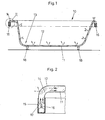
- FIG. 1 shows a schematic simplified view of a section through a bathtub 10 according to a first embodiment of the invention. It is in principle a trough made of a thermoformed plastic plate 11, for example made of polyacrylic or the like.
- the plastic plate 11 has, for example, a conventional trough shape with a trough 13, which is filled with water and a bent tub rim 14.
- the bathtub 10 is on tub feet 18th
- the bath 10 according to the invention can be illuminated over the surface of its plastic plate 11.
- FIG. 2 which represents the edge region 14 of the trough
- these lighting means 16 are seen.
- a number of such lighting means are arranged at regular intervals, for example on a strip-shaped arrangement, so that light is introduced into the end face 17 of the plastic sheet 11 on all sides.
- the plastic plate 11 acts like a light guide and the light is forwarded within the plastic plate.
- the plate 11 at least in certain areas at least on one side, preferably at the top of a light-scattering grid, the light is deflected in each case by about 90 ° and delivered over the surface of the plastic plate 11 in the trough 13, so that the surface of the bath 10 for the viewer appears bright.
- the light scattering can be, for example, the plastic plate 11 with a dot matrix 12 print or etch it on its surface or in the interior z. B. generate by means of laser beam faulty structures, which then scatter the light in the desired direction.
- the light source 16 is preferably selected bulbs with low energy consumption such. B. LED's, any type or other light-emitting diodes or the like, which can be controlled in particular electronically. This allows on the one hand an interesting control of the light emitting means 16 for generating z. B. color changing effect lighting. On the other hand, it is possible to control the lighting means 16, for example via sensors, so that the brightness of the lighting increases with a lesser influence of extraneous light or the lighting switches on when a person uses the bathtub 10.
- a composite plate which consists of a plurality of interconnected plate-shaped elements.
- This composite plate in turn has the trough shape, as explained with reference to the embodiment with reference to Figures 1 and 2.
- the composite panel can be thermoformed according to the shape of the tub and made of plastic, but in principle, the use of a correspondingly shaped laminated glass plate is possible.
- the light via suitable lamps, in particular LEDs or other light-emitting diodes fed in front of at least one of the plate-shaped elements of such a composite plate.
- the at least one illuminated plate-shaped element in which the light is fed in the end, is in turn similarly printed as in the embodiment described above at least one side, for example in a dot matrix, bar screen or the like, etched, coated, glued or internally has a faulty structure, so that a scattering effect is achieved and the light introduced at the end side into the plate-shaped element is deflected and is emitted flat from the upper side of the plate-shaped element facing the space.
- the number of light emitting diodes arranged frontally in front of at least one plate-shaped element of such a composite panel can be relatively high, depending on the type of light-emitting diodes used and the requirements for the desired illuminance and brightness. For example, you can order more than a hundred or more LEDs per meter of the face.
- the individual interconnected panel-like elements of the panel may be made of different materials, such as white glass, colored glass, float glass or corresponding plastic panels, which should be predominantly translucent, at least if they form the illuminated panel-like element or lie above the illuminated plate-shaped element. For plates of the composite material underlying the plate-shaped element, it is not necessary for them to be predominantly translucent.
Landscapes
- Engineering & Computer Science (AREA)
- Physics & Mathematics (AREA)
- Health & Medical Sciences (AREA)
- Public Health (AREA)
- General Engineering & Computer Science (AREA)
- Architecture (AREA)
- General Physics & Mathematics (AREA)
- Optics & Photonics (AREA)
- Epidemiology (AREA)
- General Health & Medical Sciences (AREA)
- Structural Engineering (AREA)
- Civil Engineering (AREA)
- Spectroscopy & Molecular Physics (AREA)
- Microelectronics & Electronic Packaging (AREA)
- Arrangement Of Elements, Cooling, Sealing, Or The Like Of Lighting Devices (AREA)
- Confectionery (AREA)
- Bidet-Like Cleaning Device And Other Flush Toilet Accessories (AREA)
- Radiation-Therapy Devices (AREA)
- Bathtubs, Showers, And Their Attachments (AREA)
Claims (15)
- Equipement sanitaire, en particulier baignoire, bac de douche ou évier sanitaire composé d'au moins un élément en forme de plaque (11) moulé selon la forme de la baignoire, du bac de douche ou de l'évier sanitaire, auquel est attribué au moins un moyen d'éclairage (16), caractérisé en ce que le moyen d'éclairage (16) diffuse depuis le côté face de la lumière dans l'élément en forme de plaque, cette lumière étant délivrée comme une lumière diffusée sur la surface de l'élément en forme de plaque en formant un angle par rapport au sens de rayonnement.
- Equipement sanitaire, en particulier baignoire, bac de douche ou évier sanitaire selon la revendication 1, caractérisé en ce que l'élément en forme de plaque (11) au moins est une plaque en plastique ou une plaque en verre.
- Equipement sanitaire, en particulier baignoire, bac de douche ou évier sanitaire selon l'une des revendications 1 ou 2, caractérisé en ce que l'élément en forme de plaque (11) au moins est imprimé, du moins unilatéralement, sur sa surface dans un motif à points, à lignes ou un motif similaire ou présente un motif à points, à lignes, ou un motif similaire pour la diffusion de lumière produit par sablage, attaque, revêtement, gravure ou collage avec des particules.
- Equipement sanitaire, en particulier baignoire, bac de douche ou évier sanitaire selon l'une des revendications 1 à 3, caractérisé en ce que l'élément en forme de plaque au moins présente à l'intérieur, c'est-à-dire à un intervalle par rapport à la surface, du moins par zones, une structure altérée produite de préférence par un rayonnement laser qui produit l'action de diffusion de la lumière qui dévie la lumière.
- Equipement sanitaire, en particulier baignoire, bac de douche ou équipement sanitaire selon l'une des revendications 1 à 4, caractérisé en ce que le ou les éléments en forme de plaque sont bordés dans la zone du rebord côté face par des cadres profilés (15).
- Equipement sanitaire, en particulier baignoire, bac de douche ou évier sanitaire selon l'une des revendications 1 à 5, caractérisé en ce que le ou les moyens d'éclairage (16) qui diffusent la lumière à partir du côté face dans l'élément en forme de plaque (11) sont recouverts par un cadre profilé (15) ou autre, du moins en partie.
- Equipement sanitaire, en particulier baignoire, bac de douche ou évier sanitaire selon l'une des revendications 1 à 6, caractérisé en ce que les moyens d'éclairage prévus sont au moins une DEL ou DEL SMD, de préférence plusieurs DEL ou DEL SMD ou d'autres diodes électroluminescentes.
- Equipement sanitaire, en particulier baignoire, bac de douche ou évier sanitaire selon l'une des revendications 1 à 7, caractérisé en ce que des moyens d'éclairage (16) qui conviennent pour délivrer une lumière colorée sont prévus, du moins en partie.
- Equipement sanitaire, en particulier baignoire, bac de douche ou évier sanitaire selon l'une des revendications 1 à 8, caractérisé en ce qu'il est prévu des dispositifs pour faire varier la luminance ou l'intensité lumineuse et/ou le mélange coloré des moyens d'éclairage.
- Equipement sanitaire, en particulier baignoire, bac de douche ou évier sanitaire selon l'une des revendications 1 à 9, caractérisé en ce qu'il est prévu des dispositifs de commande et/ou des capteurs qui assurent une commande des moyens d'éclairage en fonction de la lumière du jour incidente, en fonction de la personne présente dans la pièce ou en fonction d'un programme quelconque préalablement déterminé.
- Equipement sanitaire, en particulier baignoire, bac de douche ou évier sanitaire selon la revendication 10, caractérisé en ce qu'au moins une cellule photoélectrique et/ou un détecteur de mouvement sont prévus comme capteurs.
- Equipement sanitaire, en particulier baignoire, bac de douche ou évier sanitaire selon l'une des revendications 1 à 11, caractérisé en ce que l'élément en forme de plaque (11) au moins, se compose d'un polyacryle, en particulier d'un polyméthacryle ou d'un plastique apparenté, du moins majoritairement.
- Equipement sanitaire, en particulier baignoire, bac de douche ou évier sanitaire selon l'une des revendications 1 à 12, caractérisé en ce que le ou les éléments (11) en forme de plaque se composent d'un plastique emboutissable, perméable à la lumière, du moins en partie.
- Equipement sanitaire, en particulier baignoire, bac de douche ou évier sanitaire selon l'une des revendications 1 à 13, caractérisé en ce que cet élément en forme de plaque (11) au moins comprend un élément en forme de plaque (11) au moins qui est un élément composite composé de plusieurs plaques reliées l'une à l'autre.
- Equipement sanitaire, en particulier baignoire, bac de douche ou évier sanitaire selon la revendication 14, caractérisé en ce que les moyens d'éclairage (16) sont attribués à au moins une plaque de l'élément composite en cas d'élément (11) en forme de plaque conçu comme un élément composite et diffusent la lumière côté face dans cette plaque.
Applications Claiming Priority (3)
| Application Number | Priority Date | Filing Date | Title |
|---|---|---|---|
| DE10128688 | 2001-06-13 | ||
| DE10128688A DE10128688A1 (de) | 2000-09-01 | 2001-06-13 | Badewanne oder Duschwanne |
| PCT/EP2001/015105 WO2002100230A1 (fr) | 2001-06-13 | 2001-12-20 | Baignoire ou cuve de douche |
Publications (2)
| Publication Number | Publication Date |
|---|---|
| EP1399048A1 EP1399048A1 (fr) | 2004-03-24 |
| EP1399048B1 true EP1399048B1 (fr) | 2007-03-14 |
Family
ID=7688154
Family Applications (1)
| Application Number | Title | Priority Date | Filing Date |
|---|---|---|---|
| EP01986429A Expired - Lifetime EP1399048B1 (fr) | 2001-06-13 | 2001-12-20 | Appareil sanitaire |
Country Status (6)
| Country | Link |
|---|---|
| EP (1) | EP1399048B1 (fr) |
| JP (1) | JP2004528145A (fr) |
| AT (1) | ATE356573T1 (fr) |
| DE (3) | DE10128688A1 (fr) |
| ES (1) | ES2283448T3 (fr) |
| WO (1) | WO2002100230A1 (fr) |
Families Citing this family (11)
| Publication number | Priority date | Publication date | Assignee | Title |
|---|---|---|---|---|
| MXPA04005944A (es) * | 2001-12-20 | 2004-09-13 | Dorma Gmbh & Co Kg | Separacion de ducha con iluminacion. |
| DE20303950U1 (de) | 2003-03-11 | 2003-05-28 | Grandl, Martin, 83533 Edling | Saunakabine mit elektrischer Beleuchtungseinrichtung |
| DE10315417A1 (de) * | 2003-04-04 | 2004-11-04 | Nüsken, Frank | Lichtplatte und Verfahren zur Herstellung von 3D-Leuchtobjekten aus einer Lichtplatte |
| DE102004005873B3 (de) * | 2004-02-05 | 2005-01-05 | Dorma Gmbh + Co. Kg | Duschabtrennung |
| DE102004005896B4 (de) * | 2004-02-05 | 2006-02-09 | Dorma Gmbh + Co. Kg | Badmöbel |
| DE102004025874A1 (de) * | 2004-05-27 | 2005-12-22 | Dallmer Gmbh & Co. Kg | Ablaufrinne |
| RU2378568C2 (ru) * | 2005-07-29 | 2010-01-10 | Технодизайн Срл | Световая система для ванн, предназначенных для оздоровительных процедур с применением релаксационных методов |
| DE102006026281B3 (de) † | 2006-06-02 | 2007-11-29 | Medisana Ag | Vorrichtung zum Wiegen |
| DE102007052923A1 (de) * | 2007-11-07 | 2009-05-20 | Decs Gmbh | Sanitärgegenstand und Verfahren zu seiner Herstellung |
| DE102009011170A1 (de) | 2009-03-04 | 2010-09-23 | Alape Gmbh | Badewanne und Verfahren zu ihrer Herstellung |
| US10393363B2 (en) | 2017-04-25 | 2019-08-27 | Delta Faucet Company | Illumination device for a fluid delivery apparatus |
Family Cites Families (2)
| Publication number | Priority date | Publication date | Assignee | Title |
|---|---|---|---|---|
| GB8601617D0 (en) * | 1986-01-23 | 1986-02-26 | Ideal Standard | Moulded sanitaryware articles |
| DE19852593B4 (de) * | 1998-11-14 | 2006-03-30 | Daimlerchrysler Ag | Vorrichtung zur Beleuchtung eines Innenraumes und ihre Verwendung |
-
2001
- 2001-06-13 DE DE10128688A patent/DE10128688A1/de not_active Withdrawn
- 2001-12-20 JP JP2003503060A patent/JP2004528145A/ja active Pending
- 2001-12-20 DE DE50112208T patent/DE50112208D1/de not_active Expired - Lifetime
- 2001-12-20 ES ES01986429T patent/ES2283448T3/es not_active Expired - Lifetime
- 2001-12-20 WO PCT/EP2001/015105 patent/WO2002100230A1/fr not_active Ceased
- 2001-12-20 DE DE20121667U patent/DE20121667U1/de not_active Expired - Lifetime
- 2001-12-20 AT AT01986429T patent/ATE356573T1/de active
- 2001-12-20 EP EP01986429A patent/EP1399048B1/fr not_active Expired - Lifetime
Also Published As
| Publication number | Publication date |
|---|---|
| EP1399048A1 (fr) | 2004-03-24 |
| JP2004528145A (ja) | 2004-09-16 |
| ES2283448T3 (es) | 2007-11-01 |
| ATE356573T1 (de) | 2007-04-15 |
| DE50112208D1 (de) | 2007-04-26 |
| DE20121667U1 (de) | 2003-02-27 |
| DE10128688A1 (de) | 2002-03-28 |
| WO2002100230A1 (fr) | 2002-12-19 |
Similar Documents
| Publication | Publication Date | Title |
|---|---|---|
| EP1346178B1 (fr) | Element panneau de type sandwich | |
| DE10231502A1 (de) | Fensterelement | |
| EP1399048B1 (fr) | Appareil sanitaire | |
| DE2020808A1 (de) | Optisches Bauelement | |
| EP1176362B1 (fr) | Système à éléments luminescents plats | |
| EP1183964A1 (fr) | Meuble | |
| DE102016217949A1 (de) | Fahrzeuginnenverkleidungsteil und Leuchtelement | |
| WO2002081844A1 (fr) | Meuble urbain presentant une vitre eclairee | |
| DE19910273A1 (de) | Beleuchtungsanordnung | |
| DE202010011239U1 (de) | Beleuchtungsvorrichtung | |
| EP1355007A2 (fr) | Panneau distributeur de douche | |
| WO2015104331A2 (fr) | Dispositif d'éclairage | |
| DE10064703B4 (de) | Sandwichartiges Plattenelement | |
| EP1440649B1 (fr) | Dispositif d'émission de lumière | |
| EP1035369B1 (fr) | Système d'éclairage | |
| DE202006005429U1 (de) | Beleuchtbare Fliese | |
| DE20105323U1 (de) | Möbel | |
| EP1106915B2 (fr) | Système à éléments plats lumineux | |
| EP1106914B1 (fr) | Système à éléments luminescents plats | |
| DE10117104A1 (de) | Sandwichartiges Plattenelement | |
| DE102023105469B3 (de) | Beleuchtungseinrichtung für das Interieur eines Kraftfahrzeugs und Kraftfahrzeug | |
| DE102010037868B3 (de) | Streifenförmige Beleuchtungsvorrichtung und Seitenwand für eine Wanne mit einer solchen | |
| EP2644987A1 (fr) | Dispositif d'éclairage et procédé d'éclairage | |
| EP3458771B1 (fr) | Dispositif d'éclairage | |
| DE20121666U1 (de) | Möbelstück |
Legal Events
| Date | Code | Title | Description |
|---|---|---|---|
| PUAI | Public reference made under article 153(3) epc to a published international application that has entered the european phase |
Free format text: ORIGINAL CODE: 0009012 |
|
| 17P | Request for examination filed |
Effective date: 20040113 |
|
| AK | Designated contracting states |
Kind code of ref document: A1 Designated state(s): AT BE CH CY DE DK ES FI FR GB GR IE IT LI LU MC NL PT SE TR |
|
| AX | Request for extension of the european patent |
Extension state: AL LT LV MK RO SI |
|
| RAP1 | Party data changed (applicant data changed or rights of an application transferred) |
Owner name: KONINKLIJKE PHILIPS ELECTRONICS N.V. |
|
| RIN1 | Information on inventor provided before grant (corrected) |
Inventor name: KONINKLIJKE PHILIPS ELECTRONICS N.V. |
|
| RTI1 | Title (correction) |
Free format text: SANITARY DEVICE |
|
| GRAP | Despatch of communication of intention to grant a patent |
Free format text: ORIGINAL CODE: EPIDOSNIGR1 |
|
| RIN1 | Information on inventor provided before grant (corrected) |
Inventor name: EMDE, THOMAS Inventor name: POHL, HEINRICH ROBERT |
|
| GRAS | Grant fee paid |
Free format text: ORIGINAL CODE: EPIDOSNIGR3 |
|
| GRAA | (expected) grant |
Free format text: ORIGINAL CODE: 0009210 |
|
| AK | Designated contracting states |
Kind code of ref document: B1 Designated state(s): AT BE CH CY DE DK ES FI FR GB GR IE IT LI LU MC NL PT SE TR |
|
| PG25 | Lapsed in a contracting state [announced via postgrant information from national office to epo] |
Ref country code: NL Free format text: LAPSE BECAUSE OF FAILURE TO SUBMIT A TRANSLATION OF THE DESCRIPTION OR TO PAY THE FEE WITHIN THE PRESCRIBED TIME-LIMIT Effective date: 20070314 Ref country code: FI Free format text: LAPSE BECAUSE OF FAILURE TO SUBMIT A TRANSLATION OF THE DESCRIPTION OR TO PAY THE FEE WITHIN THE PRESCRIBED TIME-LIMIT Effective date: 20070314 Ref country code: IE Free format text: LAPSE BECAUSE OF FAILURE TO SUBMIT A TRANSLATION OF THE DESCRIPTION OR TO PAY THE FEE WITHIN THE PRESCRIBED TIME-LIMIT Effective date: 20070314 |
|
| REG | Reference to a national code |
Ref country code: GB Ref legal event code: FG4D Free format text: NOT ENGLISH |
|
| REG | Reference to a national code |
Ref country code: CH Ref legal event code: EP |
|
| REF | Corresponds to: |
Ref document number: 50112208 Country of ref document: DE Date of ref document: 20070426 Kind code of ref document: P |
|
| REG | Reference to a national code |
Ref country code: IE Ref legal event code: FG4D Free format text: LANGUAGE OF EP DOCUMENT: GERMAN |
|
| GBT | Gb: translation of ep patent filed (gb section 77(6)(a)/1977) |
Effective date: 20070518 |
|
| REG | Reference to a national code |
Ref country code: GB Ref legal event code: 746 Effective date: 20070518 |
|
| PG25 | Lapsed in a contracting state [announced via postgrant information from national office to epo] |
Ref country code: SE Free format text: LAPSE BECAUSE OF FAILURE TO SUBMIT A TRANSLATION OF THE DESCRIPTION OR TO PAY THE FEE WITHIN THE PRESCRIBED TIME-LIMIT Effective date: 20070614 |
|
| PG25 | Lapsed in a contracting state [announced via postgrant information from national office to epo] |
Ref country code: PT Free format text: LAPSE BECAUSE OF FAILURE TO SUBMIT A TRANSLATION OF THE DESCRIPTION OR TO PAY THE FEE WITHIN THE PRESCRIBED TIME-LIMIT Effective date: 20070814 |
|
| NLV1 | Nl: lapsed or annulled due to failure to fulfill the requirements of art. 29p and 29m of the patents act | ||
| ET | Fr: translation filed | ||
| REG | Reference to a national code |
Ref country code: IE Ref legal event code: FD4D |
|
| REG | Reference to a national code |
Ref country code: ES Ref legal event code: FG2A Ref document number: 2283448 Country of ref document: ES Kind code of ref document: T3 |
|
| PLBE | No opposition filed within time limit |
Free format text: ORIGINAL CODE: 0009261 |
|
| STAA | Information on the status of an ep patent application or granted ep patent |
Free format text: STATUS: NO OPPOSITION FILED WITHIN TIME LIMIT |
|
| PG25 | Lapsed in a contracting state [announced via postgrant information from national office to epo] |
Ref country code: DK Free format text: LAPSE BECAUSE OF FAILURE TO SUBMIT A TRANSLATION OF THE DESCRIPTION OR TO PAY THE FEE WITHIN THE PRESCRIBED TIME-LIMIT Effective date: 20070314 |
|
| 26N | No opposition filed |
Effective date: 20071217 |
|
| PG25 | Lapsed in a contracting state [announced via postgrant information from national office to epo] |
Ref country code: GR Free format text: LAPSE BECAUSE OF FAILURE TO SUBMIT A TRANSLATION OF THE DESCRIPTION OR TO PAY THE FEE WITHIN THE PRESCRIBED TIME-LIMIT Effective date: 20070615 |
|
| PG25 | Lapsed in a contracting state [announced via postgrant information from national office to epo] |
Ref country code: MC Free format text: LAPSE BECAUSE OF NON-PAYMENT OF DUE FEES Effective date: 20071231 |
|
| REG | Reference to a national code |
Ref country code: CH Ref legal event code: PL |
|
| PG25 | Lapsed in a contracting state [announced via postgrant information from national office to epo] |
Ref country code: LI Free format text: LAPSE BECAUSE OF NON-PAYMENT OF DUE FEES Effective date: 20071231 Ref country code: CH Free format text: LAPSE BECAUSE OF NON-PAYMENT OF DUE FEES Effective date: 20071231 |
|
| PG25 | Lapsed in a contracting state [announced via postgrant information from national office to epo] |
Ref country code: CY Free format text: LAPSE BECAUSE OF FAILURE TO SUBMIT A TRANSLATION OF THE DESCRIPTION OR TO PAY THE FEE WITHIN THE PRESCRIBED TIME-LIMIT Effective date: 20070314 |
|
| PG25 | Lapsed in a contracting state [announced via postgrant information from national office to epo] |
Ref country code: LU Free format text: LAPSE BECAUSE OF NON-PAYMENT OF DUE FEES Effective date: 20071220 |
|
| PG25 | Lapsed in a contracting state [announced via postgrant information from national office to epo] |
Ref country code: TR Free format text: LAPSE BECAUSE OF FAILURE TO SUBMIT A TRANSLATION OF THE DESCRIPTION OR TO PAY THE FEE WITHIN THE PRESCRIBED TIME-LIMIT Effective date: 20070314 |
|
| REG | Reference to a national code |
Ref country code: ES Ref legal event code: PC2A Owner name: KONINKLIJKE PHILIPS N.V. Effective date: 20140221 |
|
| REG | Reference to a national code |
Ref country code: DE Ref legal event code: R082 Ref document number: 50112208 Country of ref document: DE Representative=s name: VOLMER, GEORG, DIPL.-ING., DE |
|
| REG | Reference to a national code |
Ref country code: DE Ref legal event code: R082 Ref document number: 50112208 Country of ref document: DE Representative=s name: MEISSNER BOLTE PATENTANWAELTE RECHTSANWAELTE P, DE Effective date: 20140328 Ref country code: DE Ref legal event code: R081 Ref document number: 50112208 Country of ref document: DE Owner name: KONINKLIJKE PHILIPS N.V., NL Free format text: FORMER OWNER: KONINKLIJKE PHILIPS ELECTRONICS N.V., EINDHOVEN, NL Effective date: 20140328 Ref country code: DE Ref legal event code: R082 Ref document number: 50112208 Country of ref document: DE Representative=s name: VOLMER, GEORG, DIPL.-ING., DE Effective date: 20140328 Ref country code: DE Ref legal event code: R082 Ref document number: 50112208 Country of ref document: DE Representative=s name: MEISSNER, BOLTE & PARTNER GBR, DE Effective date: 20140328 Ref country code: DE Ref legal event code: R081 Ref document number: 50112208 Country of ref document: DE Owner name: PHILIPS LIGHTING HOLDING B.V., NL Free format text: FORMER OWNER: KONINKLIJKE PHILIPS ELECTRONICS N.V., EINDHOVEN, NL Effective date: 20140328 |
|
| REG | Reference to a national code |
Ref country code: FR Ref legal event code: CA Effective date: 20141126 Ref country code: FR Ref legal event code: CD Owner name: KONINKLIJKE PHILIPS N.V., NL Effective date: 20141126 |
|
| REG | Reference to a national code |
Ref country code: FR Ref legal event code: PLFP Year of fee payment: 15 |
|
| REG | Reference to a national code |
Ref country code: DE Ref legal event code: R082 Ref document number: 50112208 Country of ref document: DE Representative=s name: MEISSNER BOLTE PATENTANWAELTE RECHTSANWAELTE P, DE Ref country code: DE Ref legal event code: R082 Ref document number: 50112208 Country of ref document: DE Representative=s name: MEISSNER, BOLTE & PARTNER GBR, DE |
|
| REG | Reference to a national code |
Ref country code: GB Ref legal event code: 732E Free format text: REGISTERED BETWEEN 20161006 AND 20161012 |
|
| REG | Reference to a national code |
Ref country code: FR Ref legal event code: PLFP Year of fee payment: 16 |
|
| REG | Reference to a national code |
Ref country code: DE Ref legal event code: R082 Ref document number: 50112208 Country of ref document: DE Representative=s name: MEISSNER BOLTE PATENTANWAELTE RECHTSANWAELTE P, DE Ref country code: DE Ref legal event code: R081 Ref document number: 50112208 Country of ref document: DE Owner name: PHILIPS LIGHTING HOLDING B.V., NL Free format text: FORMER OWNER: KONINKLIJKE PHILIPS N.V., EINDHOVEN, NL |
|
| REG | Reference to a national code |
Ref country code: AT Ref legal event code: PC Ref document number: 356573 Country of ref document: AT Kind code of ref document: T Owner name: PHILIPS LIGHTING HOLDING B.V., NL Effective date: 20170414 |
|
| REG | Reference to a national code |
Ref country code: FR Ref legal event code: PLFP Year of fee payment: 17 |
|
| REG | Reference to a national code |
Ref country code: ES Ref legal event code: PC2A Owner name: PHILIPS LIGHTING HOLDING B.V. Effective date: 20181221 |
|
| PGFP | Annual fee paid to national office [announced via postgrant information from national office to epo] |
Ref country code: AT Payment date: 20181227 Year of fee payment: 18 |
|
| PGFP | Annual fee paid to national office [announced via postgrant information from national office to epo] |
Ref country code: BE Payment date: 20181221 Year of fee payment: 18 Ref country code: GB Payment date: 20181221 Year of fee payment: 18 Ref country code: FR Payment date: 20181231 Year of fee payment: 18 |
|
| PGFP | Annual fee paid to national office [announced via postgrant information from national office to epo] |
Ref country code: IT Payment date: 20181220 Year of fee payment: 18 Ref country code: ES Payment date: 20190131 Year of fee payment: 18 Ref country code: DE Payment date: 20190228 Year of fee payment: 18 |
|
| REG | Reference to a national code |
Ref country code: DE Ref legal event code: R119 Ref document number: 50112208 Country of ref document: DE |
|
| REG | Reference to a national code |
Ref country code: AT Ref legal event code: MM01 Ref document number: 356573 Country of ref document: AT Kind code of ref document: T Effective date: 20191220 |
|
| REG | Reference to a national code |
Ref country code: BE Ref legal event code: MM Effective date: 20191231 |
|
| GBPC | Gb: european patent ceased through non-payment of renewal fee |
Effective date: 20191220 |
|
| PG25 | Lapsed in a contracting state [announced via postgrant information from national office to epo] |
Ref country code: GB Free format text: LAPSE BECAUSE OF NON-PAYMENT OF DUE FEES Effective date: 20191220 Ref country code: IT Free format text: LAPSE BECAUSE OF NON-PAYMENT OF DUE FEES Effective date: 20191220 Ref country code: DE Free format text: LAPSE BECAUSE OF NON-PAYMENT OF DUE FEES Effective date: 20200701 Ref country code: FR Free format text: LAPSE BECAUSE OF NON-PAYMENT OF DUE FEES Effective date: 20191231 |
|
| PG25 | Lapsed in a contracting state [announced via postgrant information from national office to epo] |
Ref country code: AT Free format text: LAPSE BECAUSE OF NON-PAYMENT OF DUE FEES Effective date: 20191220 Ref country code: BE Free format text: LAPSE BECAUSE OF NON-PAYMENT OF DUE FEES Effective date: 20191231 |
|
| REG | Reference to a national code |
Ref country code: ES Ref legal event code: FD2A Effective date: 20210524 |
|
| PG25 | Lapsed in a contracting state [announced via postgrant information from national office to epo] |
Ref country code: ES Free format text: LAPSE BECAUSE OF NON-PAYMENT OF DUE FEES Effective date: 20191221 |