EP1399074B1 - Hilfszange für manuell unterstützte laparaskopische chirurgie - Google Patents
Hilfszange für manuell unterstützte laparaskopische chirurgie Download PDFInfo
- Publication number
- EP1399074B1 EP1399074B1 EP01949865A EP01949865A EP1399074B1 EP 1399074 B1 EP1399074 B1 EP 1399074B1 EP 01949865 A EP01949865 A EP 01949865A EP 01949865 A EP01949865 A EP 01949865A EP 1399074 B1 EP1399074 B1 EP 1399074B1
- Authority
- EP
- European Patent Office
- Prior art keywords
- jaws
- forceps
- plates
- hand
- actuating
- Prior art date
- Legal status (The legal status is an assumption and is not a legal conclusion. Google has not performed a legal analysis and makes no representation as to the accuracy of the status listed.)
- Expired - Lifetime
Links
- 238000002357 laparoscopic surgery Methods 0.000 title claims abstract description 16
- 238000002324 minimally invasive surgery Methods 0.000 claims abstract description 5
- 238000006073 displacement reaction Methods 0.000 claims description 6
- 239000000853 adhesive Substances 0.000 claims description 4
- 230000001070 adhesive effect Effects 0.000 claims description 4
- 238000004873 anchoring Methods 0.000 claims description 3
- 239000000463 material Substances 0.000 claims description 3
- 230000001681 protective effect Effects 0.000 claims description 3
- 210000000707 wrist Anatomy 0.000 claims description 2
- 230000002441 reversible effect Effects 0.000 claims 1
- 238000000034 method Methods 0.000 description 14
- 210000003811 finger Anatomy 0.000 description 10
- 238000001356 surgical procedure Methods 0.000 description 10
- 210000001519 tissue Anatomy 0.000 description 10
- 230000008901 benefit Effects 0.000 description 6
- 238000007789 sealing Methods 0.000 description 6
- 230000006870 function Effects 0.000 description 5
- 210000001015 abdomen Anatomy 0.000 description 4
- 210000003815 abdominal wall Anatomy 0.000 description 3
- 230000003902 lesion Effects 0.000 description 3
- 210000000056 organ Anatomy 0.000 description 3
- 230000002792 vascular Effects 0.000 description 3
- 210000000683 abdominal cavity Anatomy 0.000 description 2
- 238000013459 approach Methods 0.000 description 2
- 238000002224 dissection Methods 0.000 description 2
- 230000002496 gastric effect Effects 0.000 description 2
- 238000002955 isolation Methods 0.000 description 2
- 244000228957 Ferula foetida Species 0.000 description 1
- 238000002679 ablation Methods 0.000 description 1
- 208000007474 aortic aneurysm Diseases 0.000 description 1
- 238000010878 colorectal surgery Methods 0.000 description 1
- 230000000694 effects Effects 0.000 description 1
- 238000009297 electrocoagulation Methods 0.000 description 1
- 210000004553 finger phalanx Anatomy 0.000 description 1
- 239000007789 gas Substances 0.000 description 1
- 210000004247 hand Anatomy 0.000 description 1
- 230000002440 hepatic effect Effects 0.000 description 1
- 239000011261 inert gas Substances 0.000 description 1
- 238000003780 insertion Methods 0.000 description 1
- 230000037431 insertion Effects 0.000 description 1
- 230000003993 interaction Effects 0.000 description 1
- 230000007246 mechanism Effects 0.000 description 1
- 238000012978 minimally invasive surgical procedure Methods 0.000 description 1
- 238000012986 modification Methods 0.000 description 1
- 230000004048 modification Effects 0.000 description 1
- 238000013059 nephrectomy Methods 0.000 description 1
- 239000013307 optical fiber Substances 0.000 description 1
- 238000002559 palpation Methods 0.000 description 1
- 230000008439 repair process Effects 0.000 description 1
- 238000002271 resection Methods 0.000 description 1
- 230000035807 sensation Effects 0.000 description 1
- 230000001954 sterilising effect Effects 0.000 description 1
- 238000004659 sterilization and disinfection Methods 0.000 description 1
- 238000011477 surgical intervention Methods 0.000 description 1
- 210000003813 thumb Anatomy 0.000 description 1
- 238000012549 training Methods 0.000 description 1
Images

Classifications
-
- A—HUMAN NECESSITIES
- A61—MEDICAL OR VETERINARY SCIENCE; HYGIENE
- A61B—DIAGNOSIS; SURGERY; IDENTIFICATION
- A61B17/00—Surgical instruments, devices or methods
- A61B17/28—Surgical forceps
- A61B17/2812—Surgical forceps with a single pivotal connection
- A61B17/2841—Handles
-
- A—HUMAN NECESSITIES
- A61—MEDICAL OR VETERINARY SCIENCE; HYGIENE
- A61B—DIAGNOSIS; SURGERY; IDENTIFICATION
- A61B17/00—Surgical instruments, devices or methods
- A61B17/28—Surgical forceps
- A61B17/29—Forceps for use in minimally invasive surgery
-
- A—HUMAN NECESSITIES
- A61—MEDICAL OR VETERINARY SCIENCE; HYGIENE
- A61B—DIAGNOSIS; SURGERY; IDENTIFICATION
- A61B17/00—Surgical instruments, devices or methods
- A61B17/30—Surgical pincettes, i.e. surgical tweezers without pivotal connections
-
- A—HUMAN NECESSITIES
- A61—MEDICAL OR VETERINARY SCIENCE; HYGIENE
- A61B—DIAGNOSIS; SURGERY; IDENTIFICATION
- A61B17/00—Surgical instruments, devices or methods
- A61B17/28—Surgical forceps
- A61B17/29—Forceps for use in minimally invasive surgery
- A61B17/2909—Handles
-
- A—HUMAN NECESSITIES
- A61—MEDICAL OR VETERINARY SCIENCE; HYGIENE
- A61B—DIAGNOSIS; SURGERY; IDENTIFICATION
- A61B18/00—Surgical instruments, devices or methods for transferring non-mechanical forms of energy to or from the body
- A61B18/04—Surgical instruments, devices or methods for transferring non-mechanical forms of energy to or from the body by heating
- A61B18/12—Surgical instruments, devices or methods for transferring non-mechanical forms of energy to or from the body by heating by passing a current through the tissue to be heated, e.g. high-frequency current
- A61B18/14—Probes or electrodes therefor
- A61B18/1442—Probes having pivoting end effectors, e.g. forceps
-
- A—HUMAN NECESSITIES
- A61—MEDICAL OR VETERINARY SCIENCE; HYGIENE
- A61B—DIAGNOSIS; SURGERY; IDENTIFICATION
- A61B17/00—Surgical instruments, devices or methods
- A61B17/00234—Surgical instruments, devices or methods for minimally invasive surgery
- A61B2017/00238—Type of minimally invasive operation
- A61B2017/00265—Hand assisted surgery, i.e. minimally invasive surgery with at least part of an assisting hand inside the body
-
- A—HUMAN NECESSITIES
- A61—MEDICAL OR VETERINARY SCIENCE; HYGIENE
- A61B—DIAGNOSIS; SURGERY; IDENTIFICATION
- A61B17/00—Surgical instruments, devices or methods
- A61B2017/0042—Surgical instruments, devices or methods with special provisions for gripping
- A61B2017/00438—Surgical instruments, devices or methods with special provisions for gripping connectable to a finger
-
- A—HUMAN NECESSITIES
- A61—MEDICAL OR VETERINARY SCIENCE; HYGIENE
- A61B—DIAGNOSIS; SURGERY; IDENTIFICATION
- A61B17/00—Surgical instruments, devices or methods
- A61B17/28—Surgical forceps
- A61B17/29—Forceps for use in minimally invasive surgery
- A61B2017/2926—Details of heads or jaws
- A61B2017/2945—Curved jaws
-
- A—HUMAN NECESSITIES
- A61—MEDICAL OR VETERINARY SCIENCE; HYGIENE
- A61B—DIAGNOSIS; SURGERY; IDENTIFICATION
- A61B18/00—Surgical instruments, devices or methods for transferring non-mechanical forms of energy to or from the body
- A61B18/04—Surgical instruments, devices or methods for transferring non-mechanical forms of energy to or from the body by heating
- A61B18/12—Surgical instruments, devices or methods for transferring non-mechanical forms of energy to or from the body by heating by passing a current through the tissue to be heated, e.g. high-frequency current
- A61B18/14—Probes or electrodes therefor
- A61B2018/1405—Electrodes having a specific shape
- A61B2018/1425—Needle
- A61B2018/1432—Needle curved
-
- A—HUMAN NECESSITIES
- A61—MEDICAL OR VETERINARY SCIENCE; HYGIENE
- A61B—DIAGNOSIS; SURGERY; IDENTIFICATION
- A61B90/00—Instruments, implements or accessories specially adapted for surgery or diagnosis and not covered by any of the groups A61B1/00 - A61B50/00, e.g. for luxation treatment or for protecting wound edges
- A61B90/08—Accessories or related features not otherwise provided for
- A61B2090/0801—Prevention of accidental cutting or pricking
- A61B2090/08021—Prevention of accidental cutting or pricking of the patient or his organs
Definitions
- the present invention relates to the field of the surgical instruments, particularly for the minimally invasive, video-assisted surgery (laparoscopic and toracoscopic surgery), and more precisely it relates to an auxiliary forceps for use in the surgical interventions carried out according to the hand-assisted laparoscopic surgery (HALS) technique.
- HALS hand-assisted laparoscopic surgery
- the technique of the hand-assisted laparoscopic surgery uses the approach typical of the mini-invasive laparoscopic surgery combined with the classical approach of the open field surgery.
- the access to the surgical field is carried out through applications of trocars (generally three accesses are sufficient) for the introduction of the instruments used during the intervention and of the laparoscope, of the optical fiber type or equipped with a CCD camera, by means of which the surgeon can visually control the involved inner part of the abdomen.
- the diameter of the incisions is comprised between 5 and 25 mm.
- a working space called pneumaperitoneum
- pneumaperitoneum A working space, called pneumaperitoneum, is created in the abdomen by insufflating an inert gas to enable the surgeon to operate without significant hindrances due to the lack of suitable space.
- inert gas an inert gas to enable the surgeon to operate without significant hindrances due to the lack of suitable space.
- a further incision 5-7 cm long is made near them, through which the surgeon introduces his/her, generally non-dominant, hand in the abdomen to perform support operations (tissue displacement, retraction of the organs to be operated, palpation, interaction with other instruments, etc.).
- sealing devices In order to prevent the pneumaperitoneum to be lost through this incision, several types of sealing devices are available, intended to be applied to the incision to allow the passage of the surgeon's hand, while preventing the gas from escaping therethrough.
- the presently available sealing devices are of several types, in particular of the type comprising an adhesive flange to be fixed to the abdominal wall or of the inflatable type.
- a sealing device of the inflatable type especially easy and comfortable in use is disclosed in WO00/32117. It consists of a substantially tubular inflatable sleeve with a twisted inner cross section, to provide sealing against the surgeon's arm once her/his hand has been inserted through it, and a pair of sealing rings to provide a sealing from the innerside and the outerside of the abdominal wall in correspondence to the incision.
- Hand-assisted laparascopic surgery has been successfully applied to a wide range of surgical procedures for example gastric resection, gastric by-pass, transhiatal esophgectomy, pancreatic and hepatic surgery, nephrectomy, colorectal surgery, aortic aneurysm repairs, etc.
- the main advantages of this technique with respect to the conventional laparoscopic surgery consist, as well known, in that the surgeon regains direct tactile sensation, not allowed when remotely controlled instruments are used, and hand-eye coordination which is lost when procedures are followed through a monitor.
- the presence of the surgeon's hand in the surgical field allows for an easier and atraumatic displacement of the organs, an immediate control of dangerous situations and the possibility of performing blunt dissections.
- the possibility of using an assisting hand makes easier the surgeon task reducing the high level of training and experience usually required by the laparoscopic surgery technique.
- WO-A-980069 which corresponds to the preamble of claim 1, discloses a tiny surgical instrument directly mounted on a surgeon's fingertips in a way that the surgeon can insert his/her hand into the patient to perform surgical procedures and also to use his/her fungers to manipulate tissues.
- the instrument is provided with a tool and a mount for securing the tool to a fingertip and a retracting/deploying mechanism operably connected to the mount to permit the tool to be moved into a retracted position relative to the mount to expose the fingertip and into a deployed position relative to the mount for use of the tool.
- the tool is always available for use in surgical field and can be moved into a retracted position to allow the surgeon to manipulate tissues with the non-dominant hand.
- the main object of the present invention is to provide a structurally simple, reliable and low dimension forceps for surgical use, which can be used by the surgeon, when necessary, in video-assisted, minimally invasive surgical procedures, in particular according to the hand-assisted laparoscopic technique.
- a particular object of the present invention is to provide a forceps of the above mentioned type, whose structure, shape and dimensions is such that it can be kept at the surgeon's disposal in the abdominal cavity during the intervention in such a position that it can be quickly and easily grasped with the fingers by the surgeon, once it is necessary or, it can be parked after the use without any risk of accidentally damaging the surrounding organs and tissues.
- Another object of the present invention is to provide a forceps of the above mentioned type which is able to be kept integral to the surgeon's hand and, when not in use, during the intervention can be parked in the abdominal cavity with no risk that its jaws can constitute a danger of possible lesions to the surrounding structures.
- a further object of the present invention is to provide a forceps of the above mentioned type which is so configured that it can be operated with a minimum number of fingers (two).
- Another object of the present invention is to provide a method for performing surgical procedures with a hand-assisted laparoscopic technique, which thanks to the use of the auxiliary forceps of the above mentioned type, makes easier the surgeon's task and allows the accomplishments of operations which would be impossible to perform by manual way only.
- auxiliary forceps for video-assisted, minimally invasive surgery such as the hand-assisted laparoscopic surgery, according to the invention as claimed in claim 1, which is formed by two actuating plates, elastically hinged to each other and having a shape and dimensions such that they can be operated by keeping them between the tips of two fingers, and by two jaws each extending from a respective of said actuating plates.
- the forceps further comprises means for the temporarily connection to the surgeon's hand for maintaining the forceps at an adjustable distance from the hand not greater than a prefixed value and means for housing the jaws in a mutually side-by-side condition, within said housing means the jaws being engaged when, during the intervention, the forceps is not used.
- the forceps is fixed to the surgeon's hand by means of a rope connected to the plates and preferably having an anchoring device such as a loop made with the same rope, an elastic ring or a clamp having adjustable width and distance from the plates.
- an anchoring device such as a loop made with the same rope, an elastic ring or a clamp having adjustable width and distance from the plates.
- the housing for the jaws can be formed by a removable protective cap connected to the plates by means of an adjustable length rope, or by a seat perimetrically formed at the edge of the plates, in which case the jaws are of the retractable type as a result of an angular displacement from an operating position to a rest position within said seat and have a curved shape.
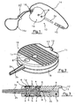
- 10 generally indicates a forceps formed by a pair of substantially circular actuating plates 1a, 1b connected to each other by means of a pin 3 extending at a chord thereof.
- Actuating plates 1a, 1b are of a very low size, sufficient to be grasped and actuated by holding them between the tips of two fingers, which corresponds to a few centimer diameter (for example, 3 cm).
- Respective jaws 2a, 2b are fixedly connected to plates 1a, 1b in any way, for example, as shown in the figures, by means of screws 4, and extend from the part diametrically opposed to pin 3 and perpendicularly to it.
- the heads of screws 4 are housed within respective seats 5 formed on plates 1a, 1b and concealed by covering caps 6, for example snap-fitted to them.
- a spring 7, for example of the flat type, is interposed between plates 1a and 1b for keeping jaws 2a, 2b spaced apart.
- a diametrical channel 9, extending from the perimetrical edge of plate 1a to the inner end of jaw 2a is formed in plate 1a to connect jaw 2a through an electric cable to an electric power source, for example to enable the forceps to be used to perform unipolar or bipolar electrocoagulation.
- a bracket 12 with a through hole 13 extends from a facing 11 formed on the perimetrical edge of plate 1a (plate 1b has a corresponding facing), from the part diametrically opposed to jaw 2a.
- a rope 14 is tied to hole 13 and a cap 15 is fixed to rope 14 for acting as a sheath for the pair of jaws 2a, b of the forceps, when it is not in use.
- Rope 14 forms a loop 14a of adjustable width by sliding a rope-clamping slider 17.
- rope 14 can be provided with an elastic ring or a fixing clamp.
- forceps is fixed by means of loop 14a to a phalanx or the wrist of the surgeon's non-dominant hand, before inserting the hand in the abdomen, while jaws 2a, 2b are placed in cap 15, whereby any risk of lesions accidentally caused to the surrounding tissues is avoided and, at the same time, jaws 2a, 2b are kept close to each other thus overcoming the bias of spring 7 and keeping forceps 10 closed.
- the surgeon takes cap 15 off and operates the forceps by holding actuating plates between two finger tips.
- the surface of plates 1a, b can be variously processed, for example by grooving, as in the present embodiment, or ribbing, curling and the like.
- protective cap 15 can be replaced by a substantially C-shaped sheath pivotally connected to one of the plates. By rotation of the sheath jaws can be engaged within C-shaped sheath or disengaged from it, thus achieving the same function of cap 15.
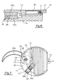
- a second embodiment of the invention is shown in figures 4, 5, 6 and 7, wherein the same components of the forceps as those of forceps of figures 1-3 are referred with the same numerals.
- the feature of the forceps according to this embodiment of the invention consists in that its jaws, indicated at 20a and 20b, are retractibly housable within a housing seat 22 formed on perimetrical edge of actuating plates 1a and 1b.
- jaws 20a and 20b have a curved shape extending from respective enlarged portion, or root, 23 and 24, at which they are hinged to actuating plates 1a and 1b by means of respective pins 21.
- Actuating plates 1a and 1b are hinged to each other through a pin 3, as in the previous embodiment, and elastic means 30, for example as shown in figure 6, are provided therebetween to keep the forceps open.
- jaws 20a, 20b are formed at respective roots 23 and 24 with a side protrusion 25 which allows a tangential force to be exerted on roots 23 and 24 to release jaws 20a, 20b and let them reach the working position shown in figure 5.
- a fastening device is provided between the actuating plates and constituted, in the present embodiment of the invention, by a substantially T-shaped bracket 26 fixed to one of the plates, for example plate 1b, by its leg 26a and extending with its transverse portion 26b within seat 22 in a groove 27 correspondingly formed in the other plate, for example plate 1a.
- a substantially T-shaped bracket 26 fixed to one of the plates, for example plate 1b, by its leg 26a and extending with its transverse portion 26b within seat 22 in a groove 27 correspondingly formed in the other plate, for example plate 1a.
- a pin 28 (figures 6 and 7) extends from a plate towards the other one and engages within a slot 29 formed in the root of the latter plate. Slot 29 is so oriented as to be perpendicular to the forceps hing when jaws are in the operating position. In this way, pin 28 can freely tilt within slot 29 when the jaws are made to space apart and keep them secured to each other when they are closed.
- an end-stroke locking device is provided, which is constituted, in the present embodiment, by a tooth 31 (figures 5 and 7), protruding from one of the plates towards the other one and snap engaging within a cavity 32 correspondingly formed on the jaws integral to the same plate. Cavity 32 and/or tooth 31 can be formed with inclined walls or sides to make easier the snap engagement/disengagement taking also advantage of the elasticity of the material.
- Other types of end-stroke locking device fully equivalent from the functional point of view, can be provided in a obvious way.
- Another way to secure the auxiliary forceps according to the invention to the surgeon's hand consists in providing a rope-anchoring adhesive member to be applied to the glove worn by the surgeon in such a position not to hinder the hand movements, for example on the back of the hand, or again at the base of a finger phalanx like a ring or hemi-ring with adhesive plate.
- the facing surfaces of the jaws of the forceps according to the invention are shaped in a substantially conventional way according to the type of function they are designed to perform; for example they can be formed with a toothed surface to better grasp the tissues and/or with a suitable seat to hold a needle thereby performing the function of a needle holder, or with other shapes resulting in an obvious way from the specific function.
- the forceps of the invention allows a number of operations to be performed which cannot carried out with the only help of the surgeon hand (vascular peduncula isolation, lynphoglandula ablation, grasping of small portions of tissues).
- the small size of the forceps (the operating plates 1a, 1b are of a diameter of few centimeters) give rise to a minimum hindrance, still they allow an easy and firm handling of the forceps when the plates are grasped with two fingers.
- they have a wide actuating surface for the fingers which makes unnecessary a third fulcrum (for example the hollow at the thumb root), as requested with the conventional, elongated structure forceps.
- the substantially circular shape makes also extremely safe the use thereof, which is practically riskless as regards possible accidental lesions to the tissues. Furthermore, it has to be pointed out that, in the case of the embodiment of the forceps in which the jaws are curved, the curved shape of the jaws offer the advantage of a minimum hindrance when the instrument is its rest condition, and allows for the use of the forceps both with a grasping and a dissecting effect on the tissues, with the possibility of surrounding vascular structures according to techniques well-known in the field.
- the forceps according to the invention is designed to be used as a disposable instrument. However, it can be made of materials able to be subjected to sterilization according to known techniques and therefore to be re-used.
- the operating plates will be made of a dark color or a transparent color, to avoid unwanted reflections which could disturb the sight of the surgical field through a monitor. The transparency of the plates also allows the sight of the otherwise concealed portion of the surgical field to be maintained through the plates.
Landscapes
- Health & Medical Sciences (AREA)
- Surgery (AREA)
- Life Sciences & Earth Sciences (AREA)
- Medical Informatics (AREA)
- Nuclear Medicine, Radiotherapy & Molecular Imaging (AREA)
- Engineering & Computer Science (AREA)
- Biomedical Technology (AREA)
- Heart & Thoracic Surgery (AREA)
- Molecular Biology (AREA)
- Animal Behavior & Ethology (AREA)
- General Health & Medical Sciences (AREA)
- Public Health (AREA)
- Veterinary Medicine (AREA)
- Ophthalmology & Optometry (AREA)
- Surgical Instruments (AREA)
- Materials For Medical Uses (AREA)
Claims (15)
- Hilfszange zur videounterstützten minimalinvasiven Chirurgie, wie die manuell unterstützte laparoskopische Chirurgie, vorgesehen, um mit der nicht dominanten Hand des Chirurgen bedient zu werden, eingeführt in einen Schnitt zum Eindringen in einen natürlichen Hohlraum eines Patientenkörpers, enthaltend zwei Betätigungsteile (1a, 1b), die elastisch aneinander angelenkt sind und eine Form und Größe haben, die geeignet ist, um, indem sie mit den Spitzen von zwei Fingern gehalten werden, bedient zu werden, und zwei Backen (2a, b; 20a, b), von denen sich jede von einem entsprechenden der Betätigungsteile erstreckt, dadurch gekennzeichnet, dass die zwei Betätigungsteile zwei Betätigungsplatten (1a, 1b) sind, und dass Schnureinrichtungen (14), die sich von den Platten aus erstrecken, zum temporären Verbinden der Zange mit der Hand eines Chirurgen während die Zange in einem einstellbaren Abstand von der Hand nicht größer als ein vorbestimmter Wert beibehalten wird, wodurch die Zange leicht zurück erhalten werden kann, wenn ihre Anwendung erforderlich ist, und, um die Backen nahe beieinander unterzubringen, Einrichtungen (15, 22) vorgesehen sind, die verbunden sind mit oder ausgebildet sind in den Platten, worin die Backen in Eingriff sind, wenn die Zange während des Betriebes nicht verwendet wird.
- Zange nach Anspruch 1, wobei die Schnureinrichtungen eine Schnur (14) enthalten, die mit den Betätigungsplatten verbunden werden kann und mit einer Verbindungsvorrichtung (14a) versehen ist, die hinsichtlich ihrer Weite und ihres Abstandes von den Platten einstellbar ist, um an einen Finger oder das Handgelenk der nicht dominanten Hand des Chirurgen angelegt zu werden.
- Zange nach Anspruch 2, wobei die Verbindungsvorrichtung eine Schlaufe (14a) ist, die aus derselben Schnur (14) besteht.
- Zange nach Anspruch 2, wobei die Verbindungsvorrichtung ein Adhäsivglied ist, das an dem Handschuh des Chirurgen in einer solchen Position angelegt wird, um die Bewegungen der Hand nicht zu behindern, an welcher die Schnur befestigt ist.
- Zange nach einem der vorhergehenden Ansprüche, wobei die Backen (2a, b) fest mit den jeweiligen Betätigungsplatten (1a, b) verbunden sind und die Unterbringungseinrichtungen für die Backen eine Schutzkappe (15) enthalten, um entfernbar an ihnen angelegt zu werden und mit den Platten durch eine Schnur (14) von einstellbarer Länge verbunden zu werden.
- Zange nach einem der Ansprüche 1 bis 4, wobei die Backen (2a, b) drehbar mit den jeweiligen Betätigungsplatten (1a, b) verbunden sind und die Unterbringungseinrichtungen einen Sitz (22) enthalten, der längs des Umfangsrandes der Platten ausgebildet ist, welche Backen eine entsprechend gekrümmte Form haben, um innerhalb des Sitzes in einer Ruheposition nachfolgend einer Winkelversetzung aus einer Betriebsposition angeordnet zu werden, wobei die Backen sich in einer im wesentlichen radialen Richtung von den Platten erstrecken, welche Backen mit einem Seitenvorsprung (25) ausgebildet sind, durch welchen eine Kraft zum Verursachen der Winkelversetzung aus der Ruheposition in die Betriebsposition ausgeübt werden kann.
- Zange nach Anspruch 6, wobei Befestigungseinrichtungen (26) vorgesehen sind, um die Betätigungsplatten nahe aneinander zu halten, wenn die Backen in ihrer Ruheposition sind.
- Zange nach Anspruch 7, wobei die Befestigungseinrichtungen eine Klammer (26) enthalten, die integral mit einer der Platten ist und sich zu der anderen Platte hin erstreckt und einen Arm (26b) hat, der in einer Nut (27) angeordnet ist, die in der anderen Platte in dem Unterbringungssitz (22) für die Backen ausgebildet ist, wodurch, wenn die Backen in dem Unterbringungssitz (22) in Eingriff sind, die Backe, die integral mit der Platte ist, in welcher die Nut (27) für den Arm ausgebildet ist, gegen den Arm anliegt, der integral mit der anderen Platte ist, wodurch die Platten aneinander verankert werden.
- Zange nach einem der Ansprüche 6, 7 oder 8, wobei ein Schlitz (29) in einer der Backen in einer solchen Weise ausgebildet ist, um in einer Position im wesentlichen orthogonal zu der Gelenkachse der Betätigungsplatten angeordnet zu sein, wenn die Backen in der Betriebsposition sind, wobei sich ein Stift (28) von der anderen Backe aus erstreckt, um innerhalb des Schlitzes in Eingriff zu sein, um jegliches relatives Verschieben der Backen zu verhindern, wenn sie winkelmäßig zwischen der Ruheposition und der Betriebsposition versetzt werden, während ihr Auseinanderspreizen während der Anwendung gestattet ist.
- Zange nach einem der Ansprüche 6 bis 9, wobei reversible Verriegelungseinrichtungen (31, 32) der Platten in der Betriebsposition und in der Ruheposition vorgesehen sind.
- Zange nach Anspruch 10, wobei die Einrichtungen zum reversiblen Verriegeln der Backen in der Betriebsposition einen Hohlraum (32), der in wenigstens einer der Backen ausgebildet ist, und einen Zahn (32) enthalten, der sich entsprechend von der entsprechenden Betätigungsplatte aus erstreckt, um reversibel innerhalb des Hohlraums in Schnappeingriff zu sein, wenn die Backen ihre Betriebsposition erreichen.
- Zange nach Anspruch 10, wobei Elastikeinrichtungen zwischen den Betätigungsplatten (1a, b) vorgesehen sind, um sie auseinander gespreizt zu halten und den Arm (26b) der Klammer (26) gegen die Backen (20a, b) zu drängen, um sie reversibel in der Ruheposition festzumachen.
- Zange nach Anspruch 1, wobei die Unterbringungseinrichtungen eine Hülle enthalten, die mit einer der Platten verbunden ist und drehbar ist, um die Backen auf eine Winkelversetzung folgend abzudecken, wenn die Zange nicht in Gebrauch ist.
- Zange nach einem der vorhergehenden Ansprüche, wobei die Betätigungsplatten aus transparentem oder dunkel gefärbtem Material hergestellt sind.
- Zange nach einem der vorhergehenden Ansprüche, wobei die Betätigungsplatten eine im wesentlichen kreisartige Form und abgerundete Ränder haben.
Applications Claiming Priority (1)
| Application Number | Priority Date | Filing Date | Title |
|---|---|---|---|
| PCT/IT2001/000298 WO2002100281A1 (en) | 2001-06-12 | 2001-06-12 | Auxiliary forceps for hand-assisted laparoscopic surgery (hals) |
Publications (2)
| Publication Number | Publication Date |
|---|---|
| EP1399074A1 EP1399074A1 (de) | 2004-03-24 |
| EP1399074B1 true EP1399074B1 (de) | 2007-05-09 |
Family
ID=11133676
Family Applications (1)
| Application Number | Title | Priority Date | Filing Date |
|---|---|---|---|
| EP01949865A Expired - Lifetime EP1399074B1 (de) | 2001-06-12 | 2001-06-12 | Hilfszange für manuell unterstützte laparaskopische chirurgie |
Country Status (6)
| Country | Link |
|---|---|
| US (1) | US7399309B2 (de) |
| EP (1) | EP1399074B1 (de) |
| JP (1) | JP2004528147A (de) |
| AT (1) | ATE361705T1 (de) |
| DE (1) | DE60128406T2 (de) |
| WO (1) | WO2002100281A1 (de) |
Families Citing this family (7)
| Publication number | Priority date | Publication date | Assignee | Title |
|---|---|---|---|---|
| US9028484B2 (en) | 2010-11-16 | 2015-05-12 | Covidien Lp | Fingertip electrosurgical instruments for use in hand-assisted surgery and systems including same |
| USD648852S1 (en) * | 2010-11-16 | 2011-11-15 | Sterilance Medical (Suzhou) Inc. | Heel incision safety lancet |
| USD806864S1 (en) * | 2016-08-19 | 2018-01-02 | Sterilance Medical (Suzhou) Inc. | Disposable heel blood collecting device |
| US20180098612A1 (en) * | 2016-10-06 | 2018-04-12 | James Lamendola | Securable Grooming Tool |
| USD872260S1 (en) * | 2017-12-11 | 2020-01-07 | Deka Products Limited Partnership | Reservoir |
| US11684382B2 (en) * | 2020-08-15 | 2023-06-27 | Edwin Ryan | Wound visualization forceps and method |
| CN113598970B (zh) * | 2021-08-20 | 2024-02-02 | 重庆市人民医院 | 一种单孔腹腔镜手术用防刺伤循环排烟装置及排烟方法 |
Family Cites Families (14)
| Publication number | Priority date | Publication date | Assignee | Title |
|---|---|---|---|---|
| US2478595A (en) * | 1948-08-24 | 1949-08-09 | Richter Bruno | Surgical forceps |
| USD253974S (en) * | 1977-11-14 | 1980-01-15 | Tweezer-Lite, Inc. | Illuminated tweezers |
| DE3722311A1 (de) | 1987-07-07 | 1989-01-19 | Braun Melsungen Ag | Gefaessklemme |
| US5062173A (en) * | 1989-11-02 | 1991-11-05 | Collins Michael C | Multifunction tool |
| JPH0741447Y2 (ja) * | 1990-06-14 | 1995-09-27 | 菊田 晴中 | 動脈手術用医療器具 |
| US5590971A (en) * | 1995-06-26 | 1997-01-07 | Pentech International Inc. | Marking pen and cap |
| ES2347584T3 (es) * | 1996-07-01 | 2010-11-02 | University Of Massachusetts | Instrumentos quirurgicos minimamente invasivos montados en las yemas de los dedos. |
| ATE320217T1 (de) * | 1996-11-18 | 2006-04-15 | Univ Massachusetts | Systeme und instrumente zur minimal invasiven chirurgie |
| US5743450A (en) * | 1996-12-05 | 1998-04-28 | Plate; Scotty Allen | Scissors retaining apparatus |
| US5893874A (en) * | 1997-02-07 | 1999-04-13 | Smith & Nephew, Inc. | Surgical instrument |
| US5921990A (en) * | 1997-08-06 | 1999-07-13 | Eagle Vision | Collagen forceps |
| US6174321B1 (en) * | 1997-08-06 | 2001-01-16 | Eagle Vision, Inc. | Collagen forceps |
| US6149642A (en) * | 1998-01-16 | 2000-11-21 | Medical Creative Technologies Inc. | Surgical instrument and method for use in hand-assisted laparoscopy |
| AU1405700A (en) | 1998-12-01 | 2000-06-19 | Atropos Limited | Laparoscopic sealed access device |
-
2001
- 2001-06-12 EP EP01949865A patent/EP1399074B1/de not_active Expired - Lifetime
- 2001-06-12 US US10/480,881 patent/US7399309B2/en not_active Expired - Fee Related
- 2001-06-12 DE DE60128406T patent/DE60128406T2/de not_active Expired - Lifetime
- 2001-06-12 AT AT01949865T patent/ATE361705T1/de not_active IP Right Cessation
- 2001-06-12 WO PCT/IT2001/000298 patent/WO2002100281A1/en not_active Ceased
- 2001-06-12 JP JP2003503110A patent/JP2004528147A/ja active Pending
Also Published As
| Publication number | Publication date |
|---|---|
| WO2002100281A1 (en) | 2002-12-19 |
| DE60128406T2 (de) | 2008-01-10 |
| EP1399074A1 (de) | 2004-03-24 |
| ATE361705T1 (de) | 2007-06-15 |
| JP2004528147A (ja) | 2004-09-16 |
| US7399309B2 (en) | 2008-07-15 |
| US20040153121A1 (en) | 2004-08-05 |
| DE60128406D1 (de) | 2007-06-21 |
Similar Documents
| Publication | Publication Date | Title |
|---|---|---|
| AU2007226579B2 (en) | Minimally invasive surgical assembly and methods | |
| US10278720B2 (en) | Pediatric combination surgical device | |
| CA2271029C (en) | Systems, methods, and instruments for minimally invasive surgery | |
| US5984938A (en) | Surgical instrument with jaws and movable internal scissors and method for use thereof | |
| US5922001A (en) | Surgical instrument with jaws and a movable internal blade member and method for use thereof | |
| US5993385A (en) | Self-aligning side-loading surgical retractor | |
| US9486238B2 (en) | Minimally invasive surgical clamps, assemblies and methods | |
| US6165184A (en) | Systems methods and instruments for minimally invasive surgery | |
| US5893863A (en) | Surgical instrument with jaws and movable internal hook member for use thereof | |
| MX2010008634A (es) | Metodo y aparato para articular la muñeca de un instrumento de agarre laparoscopico. | |
| US4051844A (en) | Telescoping neurosurgical scalp retractor | |
| WO1993018712A1 (en) | Tethered clamp retractor | |
| US6702739B2 (en) | Holder | |
| EP1804692A1 (de) | Chirurgisches mehrzweckwerkzeug | |
| EP3638136B1 (de) | Laparoskopische vorrichtungen | |
| US20080033473A1 (en) | Blunt Dissection and Tissue Elevation Instrument | |
| US20040153121A1 (en) | Auxiliary forceps for hand-assisted laparoscopic surgery ( hals) | |
| US7326228B2 (en) | Medical instrument for surgery | |
| EP2192861B1 (de) | Chirurgischer retraktor | |
| JP2004528147A5 (de) | ||
| SE1851029A1 (en) | A tool gripping device for a laparoscopic instrument | |
| WO2021211962A1 (en) | Surgical retractor tool for endoscopic and minimally-invasive surgeries | |
| Whalan | A guide to assisting at surgical operations 2: handling surgical instruments |
Legal Events
| Date | Code | Title | Description |
|---|---|---|---|
| PUAI | Public reference made under article 153(3) epc to a published international application that has entered the european phase |
Free format text: ORIGINAL CODE: 0009012 |
|
| 17P | Request for examination filed |
Effective date: 20040109 |
|
| AK | Designated contracting states |
Kind code of ref document: A1 Designated state(s): AT BE CH CY DE DK ES FI FR GB GR IE IT LI LU MC NL PT SE TR |
|
| AX | Request for extension of the european patent |
Extension state: AL LT LV MK RO SI |
|
| GRAP | Despatch of communication of intention to grant a patent |
Free format text: ORIGINAL CODE: EPIDOSNIGR1 |
|
| GRAS | Grant fee paid |
Free format text: ORIGINAL CODE: EPIDOSNIGR3 |
|
| GRAA | (expected) grant |
Free format text: ORIGINAL CODE: 0009210 |
|
| RAP1 | Party data changed (applicant data changed or rights of an application transferred) |
Owner name: SCUOLA SUPERIORE DI STUDI UNIVERSITARI E DI PERFEZ |
|
| AK | Designated contracting states |
Kind code of ref document: B1 Designated state(s): AT BE CH CY DE DK ES FI FR GB GR IE IT LI LU MC NL PT SE TR |
|
| PG25 | Lapsed in a contracting state [announced via postgrant information from national office to epo] |
Ref country code: FI Free format text: LAPSE BECAUSE OF FAILURE TO SUBMIT A TRANSLATION OF THE DESCRIPTION OR TO PAY THE FEE WITHIN THE PRESCRIBED TIME-LIMIT Effective date: 20070509 Ref country code: LI Free format text: LAPSE BECAUSE OF FAILURE TO SUBMIT A TRANSLATION OF THE DESCRIPTION OR TO PAY THE FEE WITHIN THE PRESCRIBED TIME-LIMIT Effective date: 20070509 Ref country code: CH Free format text: LAPSE BECAUSE OF FAILURE TO SUBMIT A TRANSLATION OF THE DESCRIPTION OR TO PAY THE FEE WITHIN THE PRESCRIBED TIME-LIMIT Effective date: 20070509 |
|
| REG | Reference to a national code |
Ref country code: GB Ref legal event code: FG4D |
|
| REG | Reference to a national code |
Ref country code: CH Ref legal event code: EP |
|
| REG | Reference to a national code |
Ref country code: IE Ref legal event code: FG4D |
|
| REF | Corresponds to: |
Ref document number: 60128406 Country of ref document: DE Date of ref document: 20070621 Kind code of ref document: P |
|
| PG25 | Lapsed in a contracting state [announced via postgrant information from national office to epo] |
Ref country code: SE Free format text: LAPSE BECAUSE OF FAILURE TO SUBMIT A TRANSLATION OF THE DESCRIPTION OR TO PAY THE FEE WITHIN THE PRESCRIBED TIME-LIMIT Effective date: 20070809 |
|
| PG25 | Lapsed in a contracting state [announced via postgrant information from national office to epo] |
Ref country code: ES Free format text: LAPSE BECAUSE OF FAILURE TO SUBMIT A TRANSLATION OF THE DESCRIPTION OR TO PAY THE FEE WITHIN THE PRESCRIBED TIME-LIMIT Effective date: 20070820 |
|
| ET | Fr: translation filed | ||
| NLV1 | Nl: lapsed or annulled due to failure to fulfill the requirements of art. 29p and 29m of the patents act | ||
| REG | Reference to a national code |
Ref country code: CH Ref legal event code: PL |
|
| PG25 | Lapsed in a contracting state [announced via postgrant information from national office to epo] |
Ref country code: AT Free format text: LAPSE BECAUSE OF FAILURE TO SUBMIT A TRANSLATION OF THE DESCRIPTION OR TO PAY THE FEE WITHIN THE PRESCRIBED TIME-LIMIT Effective date: 20070509 |
|
| PG25 | Lapsed in a contracting state [announced via postgrant information from national office to epo] |
Ref country code: BE Free format text: LAPSE BECAUSE OF FAILURE TO SUBMIT A TRANSLATION OF THE DESCRIPTION OR TO PAY THE FEE WITHIN THE PRESCRIBED TIME-LIMIT Effective date: 20070509 |
|
| PG25 | Lapsed in a contracting state [announced via postgrant information from national office to epo] |
Ref country code: PT Free format text: LAPSE BECAUSE OF FAILURE TO SUBMIT A TRANSLATION OF THE DESCRIPTION OR TO PAY THE FEE WITHIN THE PRESCRIBED TIME-LIMIT Effective date: 20071009 Ref country code: NL Free format text: LAPSE BECAUSE OF FAILURE TO SUBMIT A TRANSLATION OF THE DESCRIPTION OR TO PAY THE FEE WITHIN THE PRESCRIBED TIME-LIMIT Effective date: 20070509 Ref country code: DK Free format text: LAPSE BECAUSE OF FAILURE TO SUBMIT A TRANSLATION OF THE DESCRIPTION OR TO PAY THE FEE WITHIN THE PRESCRIBED TIME-LIMIT Effective date: 20070509 Ref country code: MC Free format text: LAPSE BECAUSE OF NON-PAYMENT OF DUE FEES Effective date: 20070630 |
|
| PLBE | No opposition filed within time limit |
Free format text: ORIGINAL CODE: 0009261 |
|
| STAA | Information on the status of an ep patent application or granted ep patent |
Free format text: STATUS: NO OPPOSITION FILED WITHIN TIME LIMIT |
|
| 26N | No opposition filed |
Effective date: 20080212 |
|
| PG25 | Lapsed in a contracting state [announced via postgrant information from national office to epo] |
Ref country code: GR Free format text: LAPSE BECAUSE OF FAILURE TO SUBMIT A TRANSLATION OF THE DESCRIPTION OR TO PAY THE FEE WITHIN THE PRESCRIBED TIME-LIMIT Effective date: 20070810 |
|
| PG25 | Lapsed in a contracting state [announced via postgrant information from national office to epo] |
Ref country code: IE Free format text: LAPSE BECAUSE OF NON-PAYMENT OF DUE FEES Effective date: 20070612 |
|
| PG25 | Lapsed in a contracting state [announced via postgrant information from national office to epo] |
Ref country code: CY Free format text: LAPSE BECAUSE OF FAILURE TO SUBMIT A TRANSLATION OF THE DESCRIPTION OR TO PAY THE FEE WITHIN THE PRESCRIBED TIME-LIMIT Effective date: 20070509 |
|
| PG25 | Lapsed in a contracting state [announced via postgrant information from national office to epo] |
Ref country code: LU Free format text: LAPSE BECAUSE OF NON-PAYMENT OF DUE FEES Effective date: 20070612 |
|
| PG25 | Lapsed in a contracting state [announced via postgrant information from national office to epo] |
Ref country code: TR Free format text: LAPSE BECAUSE OF FAILURE TO SUBMIT A TRANSLATION OF THE DESCRIPTION OR TO PAY THE FEE WITHIN THE PRESCRIBED TIME-LIMIT Effective date: 20070509 |
|
| PGFP | Annual fee paid to national office [announced via postgrant information from national office to epo] |
Ref country code: IT Payment date: 20110221 Year of fee payment: 11 |
|
| PGFP | Annual fee paid to national office [announced via postgrant information from national office to epo] |
Ref country code: FR Payment date: 20110630 Year of fee payment: 11 |
|
| PGFP | Annual fee paid to national office [announced via postgrant information from national office to epo] |
Ref country code: GB Payment date: 20110620 Year of fee payment: 11 |
|
| PGFP | Annual fee paid to national office [announced via postgrant information from national office to epo] |
Ref country code: DE Payment date: 20110622 Year of fee payment: 11 |
|
| GBPC | Gb: european patent ceased through non-payment of renewal fee |
Effective date: 20120612 |
|
| PG25 | Lapsed in a contracting state [announced via postgrant information from national office to epo] |
Ref country code: IT Free format text: LAPSE BECAUSE OF NON-PAYMENT OF DUE FEES Effective date: 20120612 |
|
| REG | Reference to a national code |
Ref country code: FR Ref legal event code: ST Effective date: 20130228 |
|
| REG | Reference to a national code |
Ref country code: DE Ref legal event code: R119 Ref document number: 60128406 Country of ref document: DE Effective date: 20130101 |
|
| PG25 | Lapsed in a contracting state [announced via postgrant information from national office to epo] |
Ref country code: GB Free format text: LAPSE BECAUSE OF NON-PAYMENT OF DUE FEES Effective date: 20120612 Ref country code: FR Free format text: LAPSE BECAUSE OF NON-PAYMENT OF DUE FEES Effective date: 20120702 Ref country code: DE Free format text: LAPSE BECAUSE OF NON-PAYMENT OF DUE FEES Effective date: 20130101 |