EP1399638B1 - Procede et systeme de forage hydrothermique - Google Patents
Procede et systeme de forage hydrothermique Download PDFInfo
- Publication number
- EP1399638B1 EP1399638B1 EP02734751A EP02734751A EP1399638B1 EP 1399638 B1 EP1399638 B1 EP 1399638B1 EP 02734751 A EP02734751 A EP 02734751A EP 02734751 A EP02734751 A EP 02734751A EP 1399638 B1 EP1399638 B1 EP 1399638B1
- Authority
- EP
- European Patent Office
- Prior art keywords
- fluid
- rock
- aqueous fluid
- drilling
- elements
- Prior art date
- Legal status (The legal status is an assumption and is not a legal conclusion. Google has not performed a legal analysis and makes no representation as to the accuracy of the status listed.)
- Expired - Lifetime
Links
Images
Classifications
-
- E—FIXED CONSTRUCTIONS
- E21—EARTH OR ROCK DRILLING; MINING
- E21B—EARTH OR ROCK DRILLING; OBTAINING OIL, GAS, WATER, SOLUBLE OR MELTABLE MATERIALS OR A SLURRY OF MINERALS FROM WELLS
- E21B7/00—Special methods or apparatus for drilling
- E21B7/14—Drilling by use of heat, e.g. flame drilling
-
- C—CHEMISTRY; METALLURGY
- C09—DYES; PAINTS; POLISHES; NATURAL RESINS; ADHESIVES; COMPOSITIONS NOT OTHERWISE PROVIDED FOR; APPLICATIONS OF MATERIALS NOT OTHERWISE PROVIDED FOR
- C09K—MATERIALS FOR MISCELLANEOUS APPLICATIONS, NOT PROVIDED FOR ELSEWHERE
- C09K8/00—Compositions for drilling of boreholes or wells; Compositions for treating boreholes or wells, e.g. for completion or for remedial operations
- C09K8/02—Well-drilling compositions
- C09K8/04—Aqueous well-drilling compositions
- C09K8/05—Aqueous well-drilling compositions containing inorganic compounds only, e.g. mixtures of clay and salt
-
- E—FIXED CONSTRUCTIONS
- E21—EARTH OR ROCK DRILLING; MINING
- E21B—EARTH OR ROCK DRILLING; OBTAINING OIL, GAS, WATER, SOLUBLE OR MELTABLE MATERIALS OR A SLURRY OF MINERALS FROM WELLS
- E21B36/00—Heating, cooling or insulating arrangements for boreholes or wells, e.g. for use in permafrost zones
- E21B36/008—Heating, cooling or insulating arrangements for boreholes or wells, e.g. for use in permafrost zones using chemical heat generating means
-
- E—FIXED CONSTRUCTIONS
- E21—EARTH OR ROCK DRILLING; MINING
- E21B—EARTH OR ROCK DRILLING; OBTAINING OIL, GAS, WATER, SOLUBLE OR MELTABLE MATERIALS OR A SLURRY OF MINERALS FROM WELLS
- E21B7/00—Special methods or apparatus for drilling
- E21B7/14—Drilling by use of heat, e.g. flame drilling
- E21B7/143—Drilling by use of heat, e.g. flame drilling underwater
-
- E—FIXED CONSTRUCTIONS
- E21—EARTH OR ROCK DRILLING; MINING
- E21B—EARTH OR ROCK DRILLING; OBTAINING OIL, GAS, WATER, SOLUBLE OR MELTABLE MATERIALS OR A SLURRY OF MINERALS FROM WELLS
- E21B7/00—Special methods or apparatus for drilling
- E21B7/14—Drilling by use of heat, e.g. flame drilling
- E21B7/15—Drilling by use of heat, e.g. flame drilling of electrically generated heat
Definitions
- This invention relates generally to a method and system for drilling into and through subsurface rock using high temperature aqueous solutions comprising high concentrations of hydroxyl ions.
- drilling mud A liquid commonly known as drilling mud is introduced through the drill string to cool the bit and to carry cuttings produced by the bit to the surface through the annular space between the drill string and the wall of the borehole.
- Thermal spallation is another method to drill holes through rock. Spallation, often called thermal drilling, produces thin flakes, or spalls, that flake or spall off the rock surface. In one spallation procedure, a combustion flame jet impinges on a rock surface, thereby inducing stresses high enough to cause the rock to spall. Examples of spallation drilling are disclosed in U.S. 5,771,984 and WO9603566 . Spallation drilling has the advantage in that a drilling rig need not use rotation of the drill string. Further, there is no direct contact between the effective end of the drilling apparatus and the rock being removed, thereby avoiding wear caused by abrasion at the tool-rock interface.
- a hybrid drilling system wherein spallation drilling using a flame jet is combined with mechanical cutting and erosion using ultra-high pressure hydrojets, is disclosed by J. North, S.T. Knibb, and S.M. Farouq Ali in the Journal of Canadian Petroleum Technology, Volume 40, P 67, 2001 .
- 0.075% ethanoic acid is added to the water to enhance the drilling process for limestone.
- the invention includes a method for penetrating rock of a subsurface formation, comprising:
- the invention also includes a drilling system for hydrothermally drilling a subterranean formation comprising a coiled tubing with an upper end and a lower end; a body attached to the lower end of the coiled tubing, said body having a heating chamber disposed therein and a plurality of nozzles opening through said body adjacent the bottom of the body so as to communicate with the heating chamber, said chamber capable of heating aqueous fluid, said nozzles capable of directing heated aqueous fluid to formation rock below the coiled tubing.
- the invention further includes a drilling system for hydrothermally drilling a subterranean formation comprising a coiled tubing with an upper end and a lower end; a body attached to the lower end of the coiled tubing, said body having a combustion chamber disposed therein and having a first set of nozzles opening through the bottom of the body, said first set of nozzles being capable of emitting chemical reactants and products of combustion occurring in said combustion chamber and a second set of nozzles opening through the bottom of the body adjacent to the first set of nozzles, said second set of nozzles being capable of emitting a heated aqueous fluid comprising water and hydroxides of Group I elements of The Periodic Table of Elements and mixtures thereof and said first set and second set of nozzles capable of directing heated aqueous fluid to formation rock below the coiled tubing.
- a drilling system for hydrothermally drilling a subterranean formation comprising a coiled tubing with an upper end and a lower end; a body attached to the
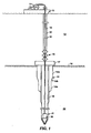
- Fig. 1 is a schematic representation in elevational view of a hydrothermal drilling operation of the present invention being performed from a marine vessel.
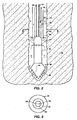
- Fig. 2 is an enlarged schematic representation, partly cross-sectional, of one embodiment of a hydrothermal drilling system that uses electrical energy to heat the drilling fluid.
- Fig. 3 is a cross-sectional view taken along line 3-3 of Fig. 2.
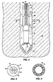
- Fig. 4 is an enlarged schematic representation, partly cross-sectional, of a second embodiment of a hydrothermal drilling system that uses chemical reaction to produce hot drilling fluid in a borehole.
- Fig. 5 is a cross-sectional view taken along line 5-5 of Fig. 4.
- Fig. 6 is a bottom view of the combustion heater illustrated in Fig. 4 showing the configuration of reactant nozzles and water nozzles.
- an aqueous fluid comprising water and hydroxides of Group I elements of The Periodic Table of Elements (i.e., The Periodic Table of Elements is the Long Form of the Table as disclosed for example in " Advanced Inorganic Chemistry", Cotton and Wilkinson, John Wiley & Sons, 1962 ) and mixtures thereof is used.
- the hydroxyl ion concentration of the hydroxides of Group I elements of The Periodic Table of Elements and mixtures thereof at ambient conditions is in the range of about 0.025 to 30 moles of hydroxyl ion per kilogram of water.
- the upper limit of the range is determined by the solubility of the Group I hydroxide. For example, this range for sodium hydroxide is 0.1 to 52 grams per 100 grams of solution.
- a fluid with high solubility for the reaction products is necessary.
- Concentrated aqueous solutions of hydroxides of alkali metals react with all subsurface rock formations and are capable of forming one or more water soluble complexes with at least one of Si or Al.
- the high hydroxyl ion concentration in the fluid provides the dual benefits of (i) enhancing the dissolution rate by fully ionizing the chemical surface groups on the formation rock, thus maximizing the density of surface sites vulnerable to hydrolysis, and (ii) enhancing solubility of reaction products by forming thermally stable soluble complexes.
- Such fluids dissolve rock and consume hydroxide stochiometrically until the hydroxyl ion concentration drops to near 0.01 moles of hydroxyl ion per kilogram of water. Therefore, with high initial hydroxyl ion concentrations, these solutions can solubilize large quantities of rock, as indicated by commercially available solutions containing up to 30 weight percent dissolved silica.
- Preferred materials to achieve hydroxyl ion concentration above 0.01 moles of hydroxyl ion per kilogram of water are alkali metal and alkaline earth metal components such as hydroxides, silicates, carbonates, bicarbonates, mixtures thereof and the like. The most preferred, nonlimiting material is sodium hydroxide.
- solutes may be added in any desired quantity to achieve other (unstated) objectives as long as the hydroxyl ion concentration is maintained.
- aqueous solutions of hydroxides of alkali metals with concentrations of at least 0.025 moles of hydroxyl ion per kilogram of water can achieve commercially viable formation penetration rates at temperatures above 500°C. For example, a rate of penetration of 12.4 ft/hr (1 mm/s) is readily achievable at 800°C.
- heating the aqueous drilling fluid to a temperature in the range of 500°C to 1400°C prior to contacting rock of a subsurface formation is preferred. Heating the aqueous drilling fluid to a temperature in the range of 800°C to 1200°C prior to contacting rock of a subsurface formation is more preferred.
- the nature of the solution is further influenced by the operating pressure. If the operating pressure is less than the vapor pressure of the initial fluid composition, the fluid will phase-separate into a low-density vapor phase consisting mainly of water and a high-density, highly-concentrated phase.
- the volume fractions and concentrations of the two phases depend on the exact conditions. For example, a solution of 20 weight percent sodium hydroxide is a single phase, homogeneous fluid at ambient conditions, but at 500°C it has a vapor pressure of about 66.2 MPa as disclosed in M.A.
- Urusova "Phase Equilibria in the Sodium Hydroxide-Water and Sodium Chloride-Water Systems at 350-550°C", Russian Journal of Inorganic Chemistry, Volume 19, 1974, p 450 .
- a formation pressure of 48 MPa it phase separates into a high-density fluid with a concentration of about 40 weight percent sodium hydroxide and a density of 1.14 g/cm 3 , and a low-density vapor phase consisting of supercritical water with between 0.13 and 0.4 weight percent sodium hydroxide and a density of 0.24 g/cm 3 .
- the mass ratio of the two phases is 1:1, whereas the volume ratio is 1:4.75.
- the high-density phase is propelled by the low-density phase onto the rock formation in the form of droplets.
- the volumetric expansion of the fluid associated with the formation of the low-density phase which can be as high as a factor of ten or more, provides high fluid and droplet impact velocities even for relatively low volumetric fluid flow rates at the wellhead.
- the phase separation concentrates the active reagents in the high-density phase, relatively dilute and benign solutions can be pumped down the drill string while still obtaining highly concentrated reactive fluid at the bottom of the borehole. In this way, it is even possible to achieve reactant solubilities that exceed saturation at wellhead (ambient) conditions.
- Jet impingement is a well-known method to achieve very large heat transfer rates primarily in cooling applications, and can simultaneously deliver the heat and reactants to the surface of the formation at a sufficient rate to maintain the dissolution reaction. This is achieved by the vigorous turbulent mixing of the fluid around the point of impingement.
- the array of impinging jets provides the added benefit of controlling the direction of drilling. Exposed surfaces in the borehole that are not directly impinged by the jets have insufficient mixing for the dissolution reaction to proceed efficiently.
- the heat transfer rate and effective dissolution rate outside the jet impingement area drops by many orders of magnitude providing spatial selectivity that enables the formation of a well-defined borehole in the direction defined by the impinging jets.
- the fluid flow rate through the jets need only be high enough to provide sufficient mixing at the formation surface to satisfy the heat and mass transfer requirements in order to maintain high dissolution rates.
- the fluid flow rate is chosen so that the rate of mass transport in the area of jet impingement with the rock face is equal to the chemical reaction rate at the operating temperature. A factor of 10 above and below this preferred rate can be used but the maximum fluid flow rate in all cases is substantially less than would be required to mechanically cut the rock in order to avoid the formation of rock chips. It is preferred to introduce the aqueous fluid into the top of the drill string at a rate in the range of about 0.1 to 10 liters per minute per square centimeter of geometric area of the bottom of the borehole.
- Rock removal is not limited to dissolution only. Dissolution processes may interact with other physical processes to affect the rate of rock penetration. For example, in permeable formations, dissolution caused by the flow of fluid through the pores can cause the rock grains to disaggregate with relatively little overall dissolution. These phenomena can increase the rate of penetration provided the disaggregated material is adequately removed from the borehole.
- dissolution may occur by chemical mechanisms other than those discussed above.
- the same hot, aqueous solution with high hydroxyl ion concentration can be used.
- the rock decomposes into an acidic gas, such as carbon dioxide or sulfur dioxide, which readily dissolves into the aqueous solution, and an insoluble precipitate. This process causes the rock to disintegrate.
- hydrothermal drilling The method for drilling into and through subsurface rock formations using an aqueous fluid comprising water and hydroxides of Group I elements of The Periodic Table of Elements and mixtures thereof will hereinafter be called hydrothermal drilling.
- the invention also includes a system for hydrothermal drilling.
- the hydrothermal drilling system comprises means for providing (i) reactive fluid and (ii) heat to the bottom of a borehole being drilled.
- Non-limiting embodiments of the system are disclosed.
- a hydrothermal drilling unit 30 is illustrated that is attached to the end of coiled tubing string 10 for drilling in a subterranean formation 22 under a body of water 13.
- the tubing string 10 is from about one to three inches (2.5 to 7.5 cm) in outside diameter, and made of steel.
- the tubing string 10 may be made of any other suitable material, including composites, and may have an outside diameter that falls outside this range.
- the tubing string 10 is preferably coiled on a large reel 11 onboard a floating vessel 12, and the tubing string 10 is unreeled as borehole 21 is drilled deeper.
- the tubing string 10 may be deployed from any suitable marine vessel, such as a mobile offshore drilling unit, a deep draft caisson vessel, a tension leg platform, or other suitable marine structure for holding the coiled tubing reel.
- a suitable marine vessel such as a mobile offshore drilling unit, a deep draft caisson vessel, a tension leg platform, or other suitable marine structure for holding the coiled tubing reel.
- the coiled tubing reel system may alternatively be positioned on the sea floor 16, in which case the coiled tubing system would have control and power modules that are operated remotely from the water's surface.
- Vessel 12 has mounted on it power sources, pumps, tanks, equipment for mud cleaning (not shown) and equipment for drilling fluid reprocessing (not shown) that is circulated in the borehole, and other equipment normally associated with a drilling operation. Such drilling equipment would be familiar to persons skilled in the art.
- a length of a rigid casing structure 15 is placed vertically into the topmost portions of formation 22 underlying the body of water 13 to prevent the formation 22 from caving into borehole 21 as drilling proceeds and to prevent uncontrolled escape of formation fluids from borehole 21.
- the length and diameter of the casing structure 15 will therefore be determined by the nature and thickness of the uppermost strata of formation 22. Techniques for installing such casing are well known.
- the casing structure 15, as shown in Fig. 1, may have different diameters, tapering from a larger diameter at the seafloor and descending to a smaller diameter that approximates the desired diameter of the borehole to be drilled.
- the casing structure's upper end 15a may have a 9 5/8-inch (24.5 cm) outside diameter
- the middle section 15b may have a 7-inch (17.8 cm) outside diameter
- the lower section 15c may have a 5-inch (12.7 cm) outside diameter.
- a conventional wellhead 17 is attached to the upper end 15a of the casing structure.
- a blowout preventor (BOP) stack 19 is positioned above the wellhead 17 for well control purposes.
- the BOP stack 19 would have conventional well control lines extending to the vessel 12 that are not shown in the Fig. 1.
- a small diameter riser 20 extends from the BOP stack 19 for transporting fluids in the annular space 23 between tubing string 10 and riser 20.
- riser 20 is from about 3 to 5 inches (7.5 to 13 cm) in outside diameter and is made of steel or other high-strength material such as a composite.
- riser 20 may have an outside diameter that falls outside this range.
- the drilling vessel 12 is preferably equipped with a suitable riser tensioner system for maintaining riser 20 in tension.
- Attached to the lower end of the tubing string 10 is a hydrothermal drilling unit 30 that is illustrated in more detail in Fig. 2.
- Fig. 2 schematically illustrates one embodiment of a hydrothermal drilling unit 30 that provides hot aqueous fluid for hydrothermal drilling.
- a heater 31 for heating the fluid to the operating temperature.
- Heater 31 may be any suitable device for this purpose. In this embodiment, the heater 31 uses electrical energy as the power source. Heater 31 is attached to the lower end of flow conduit 33. The fluid to be heated is passed to heater 31 through flow conduit 33, the downward flow of which is shown by arrow 26.
- Inside conduit 33 is an insulated electrical line 32 that provides electrical energy to heater 31 from an electrical power source (not shown) onboard vessel 12.
- the electrical conduit 32 may optionally be formed in the wall of conduit 33 or in the wall of tubing string 10 or placed separately inside coiled tubing 10 in the annular space 25 between the tubing string 10 and conduit 33, thereby providing additional space for fluid flow through conduit 33.
- the heated single or two-phase fluid flow (represented by arrows 36) is emitted through jet nozzles (not shown) located on the surface of a conical drillbit 35 attached to the distal end of heater 31, and causes dissolution of the formation 22 that is impinged by the jets.
- the number, diameter and positioning of the jets and the drilling fluid return ports (not shown) are designed for optimal drilling fluid contacting with the formation 22 and to minimize cross flow using methods of fluid dynamics familiar to those skilled in the art.
- the drilling fluid 36 may flow into the formation 22.
- the remainder of the drilling fluid will flow into the annular space between the heater 31 and the wall of borehole 21 below the deflecting skirt 37.
- the returned drilling fluid can be mixed with an aqueous circulating fluid (represented by arrows 38) flowing downwardly in annular space 25 or it can be returned to the wellhead for reprocessing through a separate return line 34 within conduit 33.
- the drilling fluid Prior to mixing with the circulating fluid in annular space between tubing string 10 and the wall of borehole 21 or returning to the wellhead for reprocessing through conduit 34, the drilling fluid is preferably heat exchanged (heat exchanger not shown in the drawings) with cooler drilling fluid flowing downwardly through conduit 33. This heat exchange would lower the temperature of the drilling fluid prior to mixing with the circulating fluid and would enhance the energy efficiency of the drilling method and system of the present invention.
- the aqueous circulating fluid is preferably passed downwardly through annular space 25 between conduit 33 and tubing string 10, and up the annular space between coiled tubing string 10 and the wall of borehole 21.
- a deflecting skirt 37 directs the circulating fluid from a downward flow through annular space 25 to an upward flow in the annular space between tubing string 10 and the wall of borehole 21.
- the circulating fluid can provide cooling to the tubing string 10 and the face of the borehole 21, help maintain borehole gauge, and help control the influx of formation fluid into the borehole 21 during drilling.
- the circulating fluid can comprise a conventional drilling fluid (or drilling mud) commonly used in rotary drilling operations.
- the circulating fluid can also contain weighting agents such as barite (a finely divided barium sulfate) and other additives that may be desired for well control purposes.
- Fig. 3 illustrates a cross-sectional view taken along lines 3-3 of Fig. 2.
- the cross-section illustrates coiled tubing 10 within borehole 21, flow conduit 33 within coiled tubing 10, flow conduit 34 and electrical cable 32 within conduit 33.
- Fig. 4 illustrates another embodiment of a system for delivering heat and reactants for hydrothermally drilling a well.
- a chemical reaction creates heat and water.
- Two or more chemical agents are introduced into the borehole 21 and are reacted at or near the bottom of the borehole 21 to produce hot water.
- the chemical agents introduced can comprise substantially any chemical or combination of chemicals that exothermically react to form water.
- Preferred chemical agents comprise a hydrogen-supplying agent and an oxygen-supplying agent.
- a suitable hydrogen-supplying agent is passed through conduit 47, located inside conduit 33, to a hydrothermal mixing block 49 that is attached to the lower end of conduit 33.
- a nonlimiting example of a hydrogen-supplying agent is hydrogen.
- a suitable oxygen-supplying agent for reacting with the hydrogen-supplying agent is passed through conduit 48, also located inside conduit 33, to the mixing block 49.
- oxygen-supplying agents are oxygen and hydrogen peroxide.
- One advantage of using hydrogen peroxide rather than oxygen to supply all or a portion of the oxidant takes advantage of the fact that hydrogen peroxide decomposes rapidly to oxygen and water at high temperatures.
- the oxidant feed to the mixing block 49 is preferably in a liquid form, thereby reducing the need for a high-pressure supply conduit 48.
- the hydrogen-supplying and the oxygen-supplying agents are shown in Fig.
- conduits 47 and 48 may optionally be located in the annular space between conduit 33 and coiled tubing 10.
- the hydrogen-supplying or oxygen-supplying agent may be injected into the circulating fluid 38 descending in the annular space 25 as plugs of gas.
- the gas plugs can be compressed by the circulating fluid 38 as the gas descends to the bottom of the borehole 21.
- Gas separation facilities (not shown) familiar to those skilled in the art could be located near the mixing block 49 to separate the gas from the circulating fluid flow for delivery to the mixing block 49.
- At least one hydrogen-supplying agent and at least one oxygen-supplying agent may be generated at high pressure either downhole or at the surface, for example, by electrolysis either in a reactor above the mixing block 49 or within the mixing block 49.
- a fluid could also be decomposed downhole into separate streams of a hydrogen-supplying agent and an oxygen-supplying agent. Decomposition may be accomplished by electrolysis or by any other suitable process using electric energy transmitted through insulated electric conductors (not shown). Gas separation facilities familiar to those skilled in the art could be located near or within the mixing block 49 to separate the hydrogen supplying agent and oxygen supplying agent streams for delivery to the combustion nozzles 43 and 44.
- the hydrogen-supplying agent and the oxygen-supplying agent are combined in mixing block 49 and passed through reactant nozzles 43.
- the combustion occurs as the reactants exit reactant nozzles 43, creating water at temperatures well above that desired for hydrothermal drilling operations.
- the amounts of the chemical reactants injected through reactant nozzles 43 are preferably regulated to produce the desired temperature when mixed with the cooling fluid flow exiting nozzles 44.
- Cooling fluid is passed through conduit 33 (shown by arrows 50) and can comprise fresh water, formation water, brackish water, or salt water.
- One or more additives including solute anions and cations or compounds to adjust or maintain pH optionally may be pre-mixed with the cooling water supply in conduit 33, or additive concentrates may be passed through conduit 34 and mixed with the cooling water downhole, or additives may be introduced directly to the superheated water produced by this embodiment.
- the resulting cooling fluid/additive mixture exits nozzles 44 and further mixes with and cools the heated water formed by the reactants exiting nozzles 43 to produce the heated single or two-phase fluid flow (represented by arrows 46) emitted through jet nozzles (not shown) located on the surface of a conical drillbit 35 attached to the distal end of combustion chamber 45, and causes dissolution of the formation 22 that is impinged by the jets.
- the number, diameter and positioning of the jets and the drilling fluid return ports (not shown) on the conical drill bit are designed for optimal drilling fluid contacting with the formation 22 and to minimize cross flow using methods of fluid dynamics familiar to those skilled in the art.
- the temperature of the drilling fluid ranges between about 500°C and 1400°C, and more preferably between about 800°C and 1200°C.
- One advantage of the combustion heating and reaction embodiments is that the cooling fluid passing through conduit 33 and the reactant streams passed through conduits 47 and 48 can be used to cool the combustion chamber 45 and the drill bit 35 to a temperature below that of the drilling fluid 46 exiting the jets in the conical drill bit 35.
- Fig. 5 illustrates a cross-sectional view taken along lines 5-5 of Fig. 4.
- the cross-section illustrates coiled tubing 10 within borehole 21, flow conduit 33 within coiled tubing 10, solute conduit 34, and conduits 47 and 48 within conduit 33.
- Fig. 6 shows a non-limiting example of a configuration of reactant nozzles 43 and cooling water nozzles 44. In this configuration, the reactant nozzles 43 and cooling water nozzles 44 are arranged in alternating relationship. Other configurations can be used in this embodiment.
- nozzles 43 and 44 illustrated in Figs. 4 and 6 will depend on the desired size of the borehole, the flow rates of combustion gases through reactant nozzles 43 and the flow rate of water through water nozzles 44. Although not required for practicing this embodiment, both nozzles 43 and 44 may have flow regulators that can be controlled remotely from vessel 12 to regulate the flow rate of fluids through the nozzles as a means of controlling the maximum temperature and temperature distribution of the drilling fluid.
- compositions and flow rates of the water forming chemical agents can be adjusted to control the amount of water produced at downhole conditions. Tests can also be performed to determine for a particular formation to be drilled an operational combination of temperature of the water, hydroxyl concentration, and solute ions that would give an acceptable penetration rate through the typical rock to be encountered during the drilling operation. Such calculations and tests would be familiar to those skilled in the art in light of the teachings of this description.
- the hydrothermal drilling method and system of this invention can be applied to any subterranean formation in which the hydrostatic head of drilling fluid in the borehole 21 produces a pressure at the bottom of the borehole that does not exceed the fracture pressure of the formation.
- Hydraulic fracturing occurs when the fluid pressure in a borehole is at such a pressure that the formation rock fails and typically forms a planar fracture.
- the pressure in the borehole is preferably at all times maintained below the formation's fracture.
- Traditional drilling mud systems familiar to people skilled in the art may be used to control the pressure in the borehole.
- the drilling fluid itself may be weighted by appropriate chemically inert additives to be used as the coolant and weighting fluid, simplifying the overall design of the drill string.
- the hydrothermal drilling systems can be provided with sensors such as gyroscopes for monitoring the orientation of the drilling system.
- the signals produced by these sensors can be used to selectively control flow and temperature distribution of the fluids passed through the dissolution jets and thereby control the direction in which the borehole is drilled.
- Precipitation of the reaction products of the present invention on and in the walls of the borehole 21 can strengthen and seal the walls against structural collapse and wellbore fluid loss thereby greatly extending time interval between casing of the borehole.
- Exposed surfaces in the borehole 21 that are not directly impinged by the jets and where the drilling fluid temperature remains high e.g., in Fig. 2, below the deflecting skirt 37 and above the distal end of the heater 31) have insufficient mixing for the dissolution reaction to result in the net removal of rock.
- the rate of reaction remains high but the rate of rock removal from the borehole wall 21 becomes mass transport limited outside the jet impingement area. Because of the poor mixing in these regions, the concentration of reaction products at the rock fluid interface increases to their respective solubility limits.
- casing may be accomplished employing conventional telescoping casing strings using methods familiar to those skilled in the art.
- the slim borehole can be cased using an expandable casing string (not shown in the drawings) that is inserted into borehole 21 and then radially expanded.
- the casing may be made of a malleable material, and when it is placed in the borehole, it can be radially expanded against the borehole wall upon application of an internal radial load.
- expandable casing are disclosed in World Intellectual Property Organization publications WO9935368 and WO9325799 .
- Suitable tracer elements can also be introduced into the drilling fluid of the hydrothermal drilling system. By measuring the concentration of tracer in the returned fluid as a function of outlet pressure, the relative permeability of the rock being penetrated can be estimated by those of ordinary skill in the art.
- the hydrothermal drilling system disclosed in this description may include one or more downhole sensors operatively associated with the coiled tubing or the hydrothermal drilling systems. These detection systems have become known in the art as “logging while drilling” or “measurement while drilling”, or simply "MWD”.
- the electric cable 32 of Fig. 2 could also optionally include a line for transmitting a signal between the subsurface and surface locations.
- hydrocarbons encountered in the formation being drilled may be converted to CO, CO 2 , CH 4 , and/or H 2 that may be returned to the surface with either the circulating fluid or the drilling fluid.
- trace elements such as sulfur and nitrogen
- these compounds could be detected in the returning fluids and used by persons skilled in the art as indicators of hydrocarbon facies encountered during drilling.
- a high-pressure, high-temperature flow unit was used to demonstrate the invention with a single jet nozzle and gravity feed of the core onto the nozzle.
- Hot, pressurized mixtures of sodium hydroxide (NaOH) and water were used as drilling fluids.
- the unit was built from high-nickel alloys to limit corrosion.
- Dual syringe pumps delivered continuous flow to the unit, with pressure maintained by a back-pressure regulator.
- the solution was heated by flowing through a coil in a furnace.
- the hot solution entered the sample holder through a small tube acting as a jet nozzle.
- the rock core was sealed on the sides in a grafoil-gasketed metal cylinder to restrict chemical attack to the external faces.
- the sealed core was free to slide vertically but not horizontally inside the sample holder.
- the sample holder was mounted with the nozzle pointing up and the rock resting directly on the nozzle.
- the flowing hot fluid impinged directly on the bottom rock face, dissolving and removing rock to form a borehole.
- gravity pushed the rock down onto the nozzle tip until the hole was drilled all the way through the rock. Completion of the hole was indicated by a sudden temperature rise past the rock.
- the core was examined ex-situ using computed x-ray tomography.
- Typical conditions were 450°C; 38 MPa (380 bar); 0.04 weight % NaOH (single phase fluid at these conditions); nozzle of 1.6 mm outer diameter, 1 mm inner diameter, 35 mm long; 1 g/s flow exiting the nozzle at 5 m/s with a Reynolds number of 35,000. Under these conditions, a 5 mm diameter hole was drilled through a 12 mm diameter, 31 mm long Berea sandstone core in 45 minutes.
- Measured rates of penetration in Berea sandstone were - 0.1 ft/hr (0.01 mm/s) at 450°C.
- the cores remained competent after drilling.
- Measured diameters of the drilled holes were 5-7 times larger than the inner diameter of the drilling nozzle.
- the rock pores surrounding the hole were filled with precipitated reaction products glazing the walls of the borehole and demonstrating the concept of self casing described above.
- Measurements of the limiting rate of penetration achievable by the methods of this invention were based on measurement of the wall recession rate using a single capillary jet at a fixed distance from the surface of a rock core.
- a down flow geometry was used with the initial spacing between the surface of the rock core and the outlet of the capillary jet typically set equal to the inner diameter of the capillary.
- Fluid dynamic modeling of this dissolution geometry for a single phase fluid has shown that the rate of wall recession along the centerline of the capillary flow is proportional to the dissolution rate, and is approximately independent of the spacing for spacing up to - 6 to 10 times the capillary inner diameter.
- Experiments were carried out inside a cold-wall, high-temperature, high-pressure autoclave at typical borehole pressures encountered during subterranean drilling operations.
- Syringe pumps delivered continuous flow of the drilling fluid to the capillary inlet, at constant capillary outlet pressure using methods familiar to those in the field.
- the drilling fluid was heated to the same temperature as the rock core by a furnace located inside the cold-wall autoclave prior to injection into the capillary inlet.
- Exposure of the rock core to the capillary jet flow was carried out under isobaric conditions for varying temperatures, exposure times, fluid flow rates and drilling fluid chemical compositions.
- fluid dynamic modeling of the wall recession rate for the single phase fluid was used to set the minimum capillary flow rate required to avoid mass transport limitations in the measured wall recession rate. Variation of the flow rate above and below this minimum value was used to verify the independence of the measured rate on jet flow velocity under the conditions of the measurement.
- the shape and depth of the hole produced in the rock core by the impinging jet flow was measured using computed x-ray tomography.
- Single crystal cylindrical quartz cores 0.635 cm in thickness and 1.0 cm in diameter with the z-axis oriented parallel to the axis of the capillary were used as standards to quantitatively measure the dependence of the rate of dissolution on temperature, capillary flow rate, exposure time and drilling fluid chemical composition.
- the use of crystalline quartz avoids the natural variability in rock cores and allows collection of quantitative data that can be reliably extrapolated.
- Typical conditions were 397°C; 37.5 MPa (375 bar); 0.4 weight % NaOH (single phase fluid at these conditions); nozzle inner diameter 0.406 mm, capillary length 5 mm long; 0.55 g/s flow exiting the nozzle. Under these conditions a quartz dissolution rate of 3.11x10 -2 moles/sq. m/s was obtained. Similar experiments were carried out under conditions where the drilling fluid is a two-phase fluid. Typical conditions were 498°C; 37.5 MPa (375 bar); 0.4 weight % NaOH (two phase fluid under these conditions); nozzle inner diameter 0.406 mm, capillary length 5 mm long; 0.55 g/s flow exiting the nozzle.
- the rate of the sandstone removal was 41 % faster than crystalline quartz while the porosity of the sandstone was only - 8.3%. This result suggests that disaggregation of the sandstone grain plays a role in measured rate of wall recession in this case.
- Solid rock cores typically 8 mm diameter and 5-8 mm long
- a solution of 45 weight % NaOH in water were sealed in a gold capsule at a fluid to rock ratio of 3:1 by weight.
- the gold capsule was pressurized to 70 MPa (700 bar) in a cold-seal static pressure vessel.
- the sample was then heated to 500°C in - 1 hour, held at temperature for 3 hours, and cooled to room temperature in - 2 hours.
- the NaOH solution remained a single-phase, high density fluid at all times.
- the gold capsule was opened and the contents were visually examined to determine the extent of chemical attack on the rock.
- disaggregation contributed up to about 70% of the rock removal rate in Berea sandstone at Reynolds numbers of - 7500-9000.
- the composition at the one to two-phase boundary is between 0.13 and 0.4 weight % NaOH.
- the invention represents an advance in the art of rock piercing means. Since it uses dissolution as the primary penetration mechanism, it does not require (i) torque transmission through the drill string, (ii) increased weight on bit, or (iii) a drilling mud system that can carry large chips along with the return flow. Also, the drilling rates do not depend on the mechanical strength of the formation, such that comparable drilling rates can be achieved in hard rock formations that are particularly difficult to drill using existing drilling technologies. Because of these features, this drilling method and system is particularly useful for drilling (i) small diameter holes, (ii) very deep or extended-reach holes, and (iii) holes in hard rock formations, although it can be used under a more general set of conditions.
- This method can also be selectively deployed in deeper portions of a pre-existing borehole in which upper formations are drilled and completed using conventional methods.
- Nonlimiting applications of this method include drilling of on- and off-shore oil and gas wells, and conventional and ultra-deep geothermal wells.
Landscapes
- Life Sciences & Earth Sciences (AREA)
- Engineering & Computer Science (AREA)
- Geology (AREA)
- Mining & Mineral Resources (AREA)
- General Life Sciences & Earth Sciences (AREA)
- Environmental & Geological Engineering (AREA)
- Fluid Mechanics (AREA)
- Physics & Mathematics (AREA)
- Geochemistry & Mineralogy (AREA)
- Chemical & Material Sciences (AREA)
- Inorganic Chemistry (AREA)
- Materials Engineering (AREA)
- Organic Chemistry (AREA)
- Earth Drilling (AREA)
- Drilling And Boring (AREA)
Claims (22)
- Procédé pour pénétrer la roche d'une formation souterraine, qui comprend les étapes qui consistent à :(a) abaisser un conduit prévu pour le transport de fluide dans un forage formé dans la formation souterraine, le conduit présentant une extrémité supérieure et une extrémité inférieure et étant adapté à chauffer et à décharger un écoulement de fluide aqueux à son extrémité inférieure,(b) introduire au niveau de l'extrémité supérieure du conduit prévu pour le transport de fluide un fluide aqueux qui comprend de l'eau et des hydroxydes d'éléments du groupe I du tableau périodique des éléments ou de mélanges de ceux-ci,(c) chauffer ledit fluide aqueux à des températures comprises entre 500° C et 1 400° C afin d'obtenir un fluide aqueux chauffé,(d) vidanger par l'extrémité inférieure du conduit prévu pour le transport de fluide le fluide aqueux chauffé afin qu'il entre en contact avec la roche de la formation souterraine et qu'il puisse en dissoudre la roche,(e) évacuer la roche dissoute et le fluide aqueux chauffé du forage par un écoulement fluide ascendant.
- Procédé selon la revendication 1, dans lequel le fluide aqueux est introduit au niveau de l'extrémité supérieure du conduit prévu pour le transport de fluide à un débit compris entre environ 0,1 et 10 litres par minute et par centimètre carré de surface géométrique du fond du forage.
- Procédé selon les revendications 1 ou 2, dans lequel le fluide aqueux chauffé est déchargé au niveau de l'extrémité inférieure du conduit prévu pour le transport de fluide à un débit tel que le débit de transport de masse dans la zone où ladite vidange du fluide aqueux chauffé est en contact avec ladite roche vaut entre 0,1 et 10 fois la vitesse de dissolution de la roche.
- Procédé selon l'une quelconque des revendications 1 à 3, dans lequel le fluide aqueux qui comprend de l'eau et des hydroxydes d'éléments du groupe I du tableau périodique des éléments ou des mélanges de ceux-ci présente une concentration en ions hydroxyle comprise entre 0,025 et 30 moles d'ions hydroxyle par kilogramme d'eau.
- Procédé selon la revendication 4, dans lequel le fluide aqueux comprend de plus des silicates, des carbonates et des bicarbonates d'éléments du groupe I et du groupe II du tableau périodique des éléments ainsi que des mélanges de ceux-ci.
- Procédé selon l'une quelconque des revendications 1 à 5, dans lequel ledit hydroxyde d'éléments du groupe I du tableau périodique des éléments est choisi dans l'ensemble constitué de l'hydroxyde de sodium, de l'hydroxyde de potassium de leurs mélanges.
- Procédé selon l'une quelconque des revendications 1 à 6, dans lequel le fluide aqueux chauffé est un fluide en deux phases qui comprend un fluide à haute densité et un fluide à basse densité.
- Procédé selon la revendication 7, dans lequel la densité dudit fluide à haute densité est comprise entre environ 0,8 et 1,8 grammes par centimètre cube et la densité dudit fluide à basse densité est comprise entre environ 0,01 et 0,5 gramme par centimètre cube.
- Procédé selon les revendications 7 ou 8, dans lequel le fluide à haute densité comprend entre environ 5 et 65 % en poids d'eau et entre environ 35 et 95 % en poids d'hydroxydes d'éléments du groupe I du tableau périodique des éléments de mélanges de ceux-ci et le fluide à basse densité comprend entre environ 99,95 et 95 % en poids d'eau et entre environ 0,05 et 5% en poids d'hydroxydes d'éléments du groupe I du tableau périodique des éléments ou de mélanges de ceux-ci.
- Procédé selon l'une quelconque des revendications 1 à 9, dans lequel ladite évacuation de la roche dissoute et du fluide aqueux chauffé est réalisée en faisant circuler un fluide aqueux de circulation de façon continue dans et à l'extérieur du conduit prévu pour le transport de fluide et contre la paroi du forage et en mélangeant le fluide aqueux de circulation avec la roche dissoute et le fluide aqueux chauffé.
- Procédé selon l'une quelconque des revendications 1 à 10, dans lequel le fluide aqueux est chauffé en utilisant des moyens électriques.
- Procédé selon l'une quelconque des revendications 1 à 11, dans lequel le chauffage du fluide aqueux est réalisé par combustion d'au moins deux réactifs chimiques, au moins un des réactifs chimiques étant choisi dans l'ensemble constitué des réactifs fournisseurs d'oxygène et au moins l'un est choisi dans le groupe constitué des réactifs fournisseurs d'hydrogène.
- Procédé selon l'une quelconque des revendications 1 à 12, qui comprend de plus l'étape qui consiste à faire progresser le conduit prévu pour le transport de fluide lorsque la dissolution de la formation souterraine augmente, afin de faire avancer le forage.
- Procédé selon l'une quelconque des revendications 1 à 13, dans lequel le conduit prévu pour le transport de fluide est un tubage spiralé, un tuyau en tronçons ou une combinaison de ceux-ci.
- Procédé selon l'une quelconque des revendications 1 à 14, qui comprend de plus l'étape d'auto-gainage du forage en faisant précipiter sur et/ou dans la surface dudit forage la roche dissoute obtenue au cours de l'étape (d).
- Procédé selon l'une quelconque des revendications 1 à 15, qui comprend de plus l'évacuation de l'écoulement fluide de l'étape (d) hors du forage et l'analyse de l'écoulement fluide afin de pouvoir détecter la présence dans l'écoulement fluide d'au moins un composé sélectionné dans l'ensemble constitué du CO, du CO2, du CH4, des oxydes de soufre et d'azote et du H2.
- Dispositif de forage (30) pour le forage hydrothermique d'une formation souterraine qui comprend un tubage spiralé (10) présentant une extrémité supérieure et une extrémité inférieure, un corps relié à l'extrémité inférieure du tubage spiralé, ledit corps présentant en son sein une chambre de chauffage (31), un fluide aqueux et un grand nombre d'ajutages qui s'ouvrent sur ledit corps adjacent au fond du corps de manière à communiquer avec la chambre de chauffage (31), ladite chambre (31) pouvant chauffer ledit fluide aqueux, lesdits ajutages pouvant diriger ledit fluide aqueux chauffé vers la formation rocheuse située en dessous du tubage spiralé (10), caractérisé en ce que ledit fluide aqueux comprend de l'eau et des hydroxydes d'éléments du groupe I du tableau périodique des éléments ou des mélanges de ceux-ci, en ce que ledit fluide aqueux chauffé vidangé dissout ladite roche afin de permettre par un écoulement fluide ascendant l'évacuation de la roche dissoute et dudit fluide aqueux chauffé.
- Dispositif de forage (30) selon la revendication 17, dans lequel la chambre de chauffage (31) utilise l'électricité comme source d'énergie de chauffage.
- Dispositif de forage (30) selon les revendications 17 ou 18, dans lequel la chambre de chauffage (31) chauffe le fluide aqueux à une température comprise entre 500° C et 1 400°C.
- Dispositif de forage (30) selon la revendication 17, dans lequel la chambre de chauffage (31) est une chambre de combustion qui présente un premier ensemble d'ajutages qui s'ouvrent au niveau du fond du corps, ledit premier ensemble d'ajutages étant capable d'émettre des réactifs chimiques et des produits de la combustion qui a lieu dans ladite chambre de combustion et un deuxième ensemble d'ajutages qui s'ouvrent au niveau du fond du corps en position adjacente au premier ensemble d'ajutages, ledit deuxième ensemble d'ajutages étant capable d'émettre le fluide aqueux chauffé qui comprend de l'eau et des hydroxydes d'élément du groupe I du tableau périodique des éléments ou des mélanges de ceux-ci, ledit premier et ledit deuxième ensemble d'ajutages étant capables de diriger le fluide aqueux chauffé vers la formation rocheuse située en dessous du tubage spiralé.
- Dispositif de forage (30) selon la revendication 20, dans lequel la combustion d'au moins deux réactifs chimiques a lieu dans la chambre de combustion, au moins un réactif chimique étant choisi dans l'ensemble constitué des réactifs fournisseurs d'oxygène et au moins un réactif chimique étant choisi dans l'ensemble constitué des réactifs fournisseurs d'hydrogène.
- Dispositif de forage selon la revendication 20, dans lequel la chambre de combustion chauffe le fluide aqueux à une température comprise entre 500° C et 1 400°C.
Applications Claiming Priority (3)
| Application Number | Priority Date | Filing Date | Title |
|---|---|---|---|
| US29898101P | 2001-06-18 | 2001-06-18 | |
| US298981P | 2001-06-18 | ||
| PCT/US2002/018242 WO2002103152A1 (fr) | 2001-06-18 | 2002-06-07 | Procede et systeme de forage hydrothermique |
Publications (2)
| Publication Number | Publication Date |
|---|---|
| EP1399638A1 EP1399638A1 (fr) | 2004-03-24 |
| EP1399638B1 true EP1399638B1 (fr) | 2007-08-08 |
Family
ID=23152835
Family Applications (1)
| Application Number | Title | Priority Date | Filing Date |
|---|---|---|---|
| EP02734751A Expired - Lifetime EP1399638B1 (fr) | 2001-06-18 | 2002-06-07 | Procede et systeme de forage hydrothermique |
Country Status (7)
| Country | Link |
|---|---|
| US (1) | US6742603B2 (fr) |
| EP (1) | EP1399638B1 (fr) |
| AT (1) | ATE369479T1 (fr) |
| AU (1) | AU2002305894B2 (fr) |
| CA (1) | CA2449302C (fr) |
| DE (1) | DE60221667D1 (fr) |
| WO (1) | WO2002103152A1 (fr) |
Families Citing this family (35)
| Publication number | Priority date | Publication date | Assignee | Title |
|---|---|---|---|---|
| US20030123393A1 (en) * | 2002-01-03 | 2003-07-03 | Feuerstraeter Mark T. | Method and apparatus for priority based flow control in an ethernet architecture |
| US6772847B2 (en) * | 2002-02-26 | 2004-08-10 | Bj Services Company | Chemically enhanced drilling methods |
| WO2006063200A2 (fr) * | 2004-12-09 | 2006-06-15 | Smith David R | Procede et appareil permettant de delivrer de l'energie a un systeme puits |
| US7380605B1 (en) * | 2005-01-31 | 2008-06-03 | Wolf Clifton E | Energy transfer loop apparatus and method of installation |
| US20080093125A1 (en) * | 2006-03-27 | 2008-04-24 | Potter Drilling, Llc | Method and System for Forming a Non-Circular Borehole |
| GB2454698B (en) * | 2007-11-15 | 2013-04-10 | Schlumberger Holdings | Gas cutting borehole drilling apparatus |
| US7703527B2 (en) * | 2007-11-26 | 2010-04-27 | Schlumberger Technology Corporation | Aqueous two-phase emulsion gel systems for zone isolation |
| US8393410B2 (en) * | 2007-12-20 | 2013-03-12 | Massachusetts Institute Of Technology | Millimeter-wave drilling system |
| US8257147B2 (en) * | 2008-03-10 | 2012-09-04 | Regency Technologies, Llc | Method and apparatus for jet-assisted drilling or cutting |
| CA2740059A1 (fr) * | 2008-10-08 | 2010-04-15 | Potter Drilling, Inc. | Procedes et dispositif d'amelioration de trou de puits |
| WO2010043239A1 (fr) | 2008-10-15 | 2010-04-22 | Tctm Limited | Compositions de réduction de la viscosité du pétrole par émission de gaz pour stimuler la couche productive d’un gisement de pétrole |
| US8081796B2 (en) * | 2008-11-24 | 2011-12-20 | Ingrain, Inc. | Method for determining properties of fractured rock formations using computer tomograpic images thereof |
| US8085974B2 (en) * | 2008-11-24 | 2011-12-27 | Ingrain, Inc. | Method for determining elastic-wave attenuation of rock formations using computer tomograpic images thereof |
| US8155377B2 (en) * | 2008-11-24 | 2012-04-10 | Ingrain, Inc. | Method for determining rock physics relationships using computer tomographic images thereof |
| US8081802B2 (en) * | 2008-11-29 | 2011-12-20 | Ingrain, Inc. | Method for determining permeability of rock formation using computer tomograpic images thereof |
| EP2379835A1 (fr) | 2008-12-23 | 2011-10-26 | ETH Zurich | Forage de roches à de grandes profondeurs par fragmentation thermique en utilisant les réactions hautement exothermiques se déroulant dans un milieu de fluide de forage à base d'eau |
| US20100184631A1 (en) * | 2009-01-16 | 2010-07-22 | Schlumberger Technology Corporation | Provision of viscous compositions below ground |
| US20100181110A1 (en) * | 2009-01-20 | 2010-07-22 | Harr Robert E | Green directional drilling fluid composition |
| US8267197B2 (en) * | 2009-08-25 | 2012-09-18 | Baker Hughes Incorporated | Apparatus and methods for controlling bottomhole assembly temperature during a pause in drilling boreholes |
| WO2012015528A1 (fr) * | 2010-07-30 | 2012-02-02 | Exxonmobil Upstream Research Company | Extraction de fluide d'hydrocarbure améliorée par l'intermédiaire d'un écrasement de formation |
| US20130032398A1 (en) * | 2011-08-02 | 2013-02-07 | Halliburton Energy Services, Inc. | Pulsed-Electric Drilling Systems and Methods with Reverse Circulation |
| EP2917484B1 (fr) * | 2013-01-21 | 2022-12-21 | Halliburton Energy Services, Inc. | Système d'échantillonnage de fluide de forage et échangeur de chaleur d'échantillonnage |
| JP2015117945A (ja) * | 2013-12-16 | 2015-06-25 | 信吉 森元 | 放射能汚染水の処理方法及び原子炉設備の封印処理方法 |
| CZ306133B6 (cs) * | 2014-04-09 | 2016-08-17 | Galexum Technologies Ag | Způsob těžby uhlovodíků pomocí plynů, systém a zařízení k provádění tohoto způsobu |
| WO2015175703A1 (fr) * | 2014-05-13 | 2015-11-19 | Cauchy Charles J | Échangeur de chaleur à boucle souterraine à insertion directe |
| US10471484B2 (en) | 2014-10-17 | 2019-11-12 | Frx Inc | Injection tip and method for nucleating and propagating hydraulic fractures from probe rods |
| DE102015108648B3 (de) * | 2015-06-01 | 2016-09-01 | Nobuyoshi Morimoto | Verfahren zum Verarbeiten von strahlungsverunreinigtem Wasser und Verfahren zum Versiegeln eines Kernkraftwerks |
| US11029062B2 (en) * | 2019-07-25 | 2021-06-08 | Strabo Engineering, LLC | Geothermal heat mining system |
| US11891894B2 (en) * | 2019-09-24 | 2024-02-06 | Halliburton Energy Services, Inc. | Pulsed-power drilling fluid property management using downhole mixer |
| CA3100013C (fr) | 2020-04-21 | 2023-03-14 | Eavor Technologies Inc. | Methode de formation de puits geothermiques de grande efficacite au moyen de materiaux a changement de phase |
| PE20230970A1 (es) | 2020-08-28 | 2023-06-16 | Eavor Tech Inc | Refrigeracion para perforacion de pozos geotermicos |
| CA3121345C (fr) * | 2021-01-19 | 2023-06-27 | Hc Properties Inc. | Echangeur de chaleur au sol |
| JP2024504128A (ja) * | 2021-01-22 | 2024-01-30 | ストラボ エンジニアリング、エルエルシー | 破砕ドリル・ヘッド及びこれに関連する方法 |
| US12338713B2 (en) * | 2022-09-07 | 2025-06-24 | Bisn Tec Ltd. | One trip system to set an alloy seal and mill through |
| CN116122722B (zh) * | 2023-03-09 | 2025-12-12 | 太原理工大学 | 一种用于冰层热水钻的再热引射式喷嘴钻头及钻进方法 |
Family Cites Families (21)
| Publication number | Priority date | Publication date | Assignee | Title |
|---|---|---|---|---|
| US2258001A (en) | 1938-12-23 | 1941-10-07 | Dow Chemical Co | Subterranean boring |
| US2833516A (en) * | 1952-02-21 | 1958-05-06 | Svenska Skifferolje Ab | Method of driving holes in bituminous strata |
| US3112800A (en) * | 1959-08-28 | 1963-12-03 | Phillips Petroleum Co | Method of drilling with high velocity jet cutter rock bit |
| US3467206A (en) | 1967-07-07 | 1969-09-16 | Gulf Research Development Co | Plasma drilling |
| US4190121A (en) * | 1976-02-20 | 1980-02-26 | Messerschmitt-Bolkow-Blohm Gmbh | Thermal drilling device |
| US4085799A (en) | 1976-11-18 | 1978-04-25 | Texaco Inc. | Oil recovery process by in situ emulsification |
| US4212353A (en) * | 1978-06-30 | 1980-07-15 | Texaco Inc. | Hydraulic mining technique for recovering bitumen from tar sand deposit |
| FR2483509A1 (fr) * | 1980-05-28 | 1981-12-04 | Remlinger Francois | Flexible pour le forage thermique de galeries dans des veines de charbon |
| US4431069A (en) * | 1980-07-17 | 1984-02-14 | Dickinson Iii Ben W O | Method and apparatus for forming and using a bore hole |
| US5232627A (en) | 1985-07-05 | 1993-08-03 | The Dow Chemical Company | Adducts of clay and activated mixed metal oxides |
| US5176210A (en) * | 1990-07-06 | 1993-01-05 | Arctic Systems Limited | Thermochemical ice melting |
| MY108743A (en) | 1992-06-09 | 1996-11-30 | Shell Int Research | Method of greating a wellbore in an underground formation |
| US5853056A (en) * | 1993-10-01 | 1998-12-29 | Landers; Carl W. | Method of and apparatus for horizontal well drilling |
| WO1996003566A2 (fr) | 1994-07-26 | 1996-02-08 | John North | Perfectionnements se rapporant aux forages pratiques a l'aide d'un systeme de forage par ecaillage thermique comprenant une chambre de combustion ainsi qu'un systeme de separation gaz/liquide par hydrocyclone ou par generateur a vortex |
| US5771984A (en) | 1995-05-19 | 1998-06-30 | Massachusetts Institute Of Technology | Continuous drilling of vertical boreholes by thermal processes: including rock spallation and fusion |
| DE19533765C1 (de) | 1995-09-12 | 1996-10-31 | Kunkel Klaus Dr Ing | Verfahren und Vorrichtung zur Herstellung von Bohrlöchern |
| US5735355A (en) * | 1996-07-01 | 1998-04-07 | The Regents Of The University Of California | Rock melting tool with annealer section |
| OA11527A (en) | 1997-12-31 | 2004-02-04 | Shell Int Research | Method for drilling and completing a hydrocarbon production well. |
| US6152356A (en) * | 1999-03-23 | 2000-11-28 | Minden; Carl S. | Hydraulic mining of tar sand bitumen with aggregate material |
| US20030029617A1 (en) * | 2001-08-09 | 2003-02-13 | Anadarko Petroleum Company | Apparatus, method and system for single well solution-mining |
| US6460632B1 (en) * | 2002-04-05 | 2002-10-08 | Halliburton Energy Services, Inc. | Methods of drilling well bores |
-
2002
- 2002-06-07 EP EP02734751A patent/EP1399638B1/fr not_active Expired - Lifetime
- 2002-06-07 AU AU2002305894A patent/AU2002305894B2/en not_active Expired
- 2002-06-07 CA CA002449302A patent/CA2449302C/fr not_active Expired - Lifetime
- 2002-06-07 AT AT02734751T patent/ATE369479T1/de not_active IP Right Cessation
- 2002-06-07 US US10/164,872 patent/US6742603B2/en not_active Expired - Lifetime
- 2002-06-07 WO PCT/US2002/018242 patent/WO2002103152A1/fr not_active Ceased
- 2002-06-07 DE DE60221667T patent/DE60221667D1/de not_active Expired - Lifetime
Also Published As
| Publication number | Publication date |
|---|---|
| US6742603B2 (en) | 2004-06-01 |
| US20030121701A1 (en) | 2003-07-03 |
| ATE369479T1 (de) | 2007-08-15 |
| EP1399638A1 (fr) | 2004-03-24 |
| CA2449302C (fr) | 2010-03-02 |
| DE60221667D1 (de) | 2007-09-20 |
| AU2002305894B2 (en) | 2007-03-15 |
| CA2449302A1 (fr) | 2002-12-27 |
| WO2002103152A1 (fr) | 2002-12-27 |
Similar Documents
| Publication | Publication Date | Title |
|---|---|---|
| EP1399638B1 (fr) | Procede et systeme de forage hydrothermique | |
| AU2002305894A1 (en) | Hydrothermal drilling method and system | |
| US8235140B2 (en) | Methods and apparatus for thermal drilling | |
| US8789591B2 (en) | Method and apparatus to release energy in a well | |
| US20110174537A1 (en) | Method and System for Forming a Non-Circular Borehole | |
| BR112013004260B1 (pt) | Aparelho para tratar termicamente um reservatório de óleo | |
| WO1996003566A2 (fr) | Perfectionnements se rapporant aux forages pratiques a l'aide d'un systeme de forage par ecaillage thermique comprenant une chambre de combustion ainsi qu'un systeme de separation gaz/liquide par hydrocyclone ou par generateur a vortex | |
| CN108222892A (zh) | 一种连续开采海洋天然气水合物的开采装置及方法 | |
| US9022139B2 (en) | Gas cutting borehole drilling apparatus | |
| CN106545325A (zh) | 一种支撑海洋天然气水合物增产裂缝的装置及方法 | |
| WO2010042720A2 (fr) | Procédés et dispositif de forage thermique | |
| CN207715130U (zh) | 一种连续开采海洋天然气水合物的开采装置 | |
| Čambál et al. | INNOVATIVE METHODS IN ROCK DISINTEGRATION | |
| Chandelle et al. | Belgo German experiment on underground gasification | |
| Milligan et al. | Coiled-tubing drilling of horizontal sidetrack in House Mountain Field, Alberta | |
| US20080149389A1 (en) | Method of Using the Earth Mantle Substance for Hydrogen Production |
Legal Events
| Date | Code | Title | Description |
|---|---|---|---|
| PUAI | Public reference made under article 153(3) epc to a published international application that has entered the european phase |
Free format text: ORIGINAL CODE: 0009012 |
|
| 17P | Request for examination filed |
Effective date: 20040112 |
|
| AK | Designated contracting states |
Kind code of ref document: A1 Designated state(s): AT BE CH CY DE DK ES FI FR GB GR IE IT LI LU MC NL PT SE TR |
|
| AX | Request for extension of the european patent |
Extension state: AL LT LV MK RO SI |
|
| GRAJ | Information related to disapproval of communication of intention to grant by the applicant or resumption of examination proceedings by the epo deleted |
Free format text: ORIGINAL CODE: EPIDOSDIGR1 |
|
| GRAP | Despatch of communication of intention to grant a patent |
Free format text: ORIGINAL CODE: EPIDOSNIGR1 |
|
| RIC1 | Information provided on ipc code assigned before grant |
Ipc: C09K 8/04 20060101ALI20070213BHEP Ipc: E21B 36/00 20060101ALI20070213BHEP Ipc: E21B 7/15 20060101ALI20070213BHEP Ipc: E21B 7/14 20060101AFI20070213BHEP |
|
| RIN1 | Information on inventor provided before grant (corrected) |
Inventor name: ERTAS, MEHMET, D. Inventor name: HERHOLD, AMY, B. Inventor name: HIRSCH, MWALIMU, L.,C/O IFUNDA TECHNICAL Inventor name: POLIZZOTTI, RICHARD, S. |
|
| GRAS | Grant fee paid |
Free format text: ORIGINAL CODE: EPIDOSNIGR3 |
|
| GRAA | (expected) grant |
Free format text: ORIGINAL CODE: 0009210 |
|
| AK | Designated contracting states |
Kind code of ref document: B1 Designated state(s): AT BE CH CY DE DK ES FI FR GB GR IE IT LI LU MC NL PT SE TR |
|
| REG | Reference to a national code |
Ref country code: GB Ref legal event code: FG4D |
|
| REG | Reference to a national code |
Ref country code: CH Ref legal event code: EP |
|
| REG | Reference to a national code |
Ref country code: IE Ref legal event code: FG4D |
|
| REF | Corresponds to: |
Ref document number: 60221667 Country of ref document: DE Date of ref document: 20070920 Kind code of ref document: P |
|
| PG25 | Lapsed in a contracting state [announced via postgrant information from national office to epo] |
Ref country code: FI Free format text: LAPSE BECAUSE OF FAILURE TO SUBMIT A TRANSLATION OF THE DESCRIPTION OR TO PAY THE FEE WITHIN THE PRESCRIBED TIME-LIMIT Effective date: 20070808 Ref country code: ES Free format text: LAPSE BECAUSE OF FAILURE TO SUBMIT A TRANSLATION OF THE DESCRIPTION OR TO PAY THE FEE WITHIN THE PRESCRIBED TIME-LIMIT Effective date: 20071119 Ref country code: NL Free format text: LAPSE BECAUSE OF FAILURE TO SUBMIT A TRANSLATION OF THE DESCRIPTION OR TO PAY THE FEE WITHIN THE PRESCRIBED TIME-LIMIT Effective date: 20070808 |
|
| NLV1 | Nl: lapsed or annulled due to failure to fulfill the requirements of art. 29p and 29m of the patents act | ||
| REG | Reference to a national code |
Ref country code: CH Ref legal event code: PL |
|
| PG25 | Lapsed in a contracting state [announced via postgrant information from national office to epo] |
Ref country code: AT Free format text: LAPSE BECAUSE OF FAILURE TO SUBMIT A TRANSLATION OF THE DESCRIPTION OR TO PAY THE FEE WITHIN THE PRESCRIBED TIME-LIMIT Effective date: 20070808 Ref country code: CH Free format text: LAPSE BECAUSE OF FAILURE TO SUBMIT A TRANSLATION OF THE DESCRIPTION OR TO PAY THE FEE WITHIN THE PRESCRIBED TIME-LIMIT Effective date: 20070808 Ref country code: LI Free format text: LAPSE BECAUSE OF FAILURE TO SUBMIT A TRANSLATION OF THE DESCRIPTION OR TO PAY THE FEE WITHIN THE PRESCRIBED TIME-LIMIT Effective date: 20070808 |
|
| PG25 | Lapsed in a contracting state [announced via postgrant information from national office to epo] |
Ref country code: BE Free format text: LAPSE BECAUSE OF FAILURE TO SUBMIT A TRANSLATION OF THE DESCRIPTION OR TO PAY THE FEE WITHIN THE PRESCRIBED TIME-LIMIT Effective date: 20070808 |
|
| EN | Fr: translation not filed | ||
| PG25 | Lapsed in a contracting state [announced via postgrant information from national office to epo] |
Ref country code: DK Free format text: LAPSE BECAUSE OF FAILURE TO SUBMIT A TRANSLATION OF THE DESCRIPTION OR TO PAY THE FEE WITHIN THE PRESCRIBED TIME-LIMIT Effective date: 20070808 Ref country code: GR Free format text: LAPSE BECAUSE OF FAILURE TO SUBMIT A TRANSLATION OF THE DESCRIPTION OR TO PAY THE FEE WITHIN THE PRESCRIBED TIME-LIMIT Effective date: 20071109 |
|
| PG25 | Lapsed in a contracting state [announced via postgrant information from national office to epo] |
Ref country code: PT Free format text: LAPSE BECAUSE OF FAILURE TO SUBMIT A TRANSLATION OF THE DESCRIPTION OR TO PAY THE FEE WITHIN THE PRESCRIBED TIME-LIMIT Effective date: 20080108 |
|
| PLBE | No opposition filed within time limit |
Free format text: ORIGINAL CODE: 0009261 |
|
| STAA | Information on the status of an ep patent application or granted ep patent |
Free format text: STATUS: NO OPPOSITION FILED WITHIN TIME LIMIT |
|
| PG25 | Lapsed in a contracting state [announced via postgrant information from national office to epo] |
Ref country code: SE Free format text: LAPSE BECAUSE OF FAILURE TO SUBMIT A TRANSLATION OF THE DESCRIPTION OR TO PAY THE FEE WITHIN THE PRESCRIBED TIME-LIMIT Effective date: 20071108 |
|
| 26N | No opposition filed |
Effective date: 20080509 |
|
| PG25 | Lapsed in a contracting state [announced via postgrant information from national office to epo] |
Ref country code: DE Free format text: LAPSE BECAUSE OF FAILURE TO SUBMIT A TRANSLATION OF THE DESCRIPTION OR TO PAY THE FEE WITHIN THE PRESCRIBED TIME-LIMIT Effective date: 20071109 |
|
| PG25 | Lapsed in a contracting state [announced via postgrant information from national office to epo] |
Ref country code: MC Free format text: LAPSE BECAUSE OF NON-PAYMENT OF DUE FEES Effective date: 20080630 |
|
| GBPC | Gb: european patent ceased through non-payment of renewal fee |
Effective date: 20080607 |
|
| PG25 | Lapsed in a contracting state [announced via postgrant information from national office to epo] |
Ref country code: IE Free format text: LAPSE BECAUSE OF NON-PAYMENT OF DUE FEES Effective date: 20080609 |
|
| PG25 | Lapsed in a contracting state [announced via postgrant information from national office to epo] |
Ref country code: GB Free format text: LAPSE BECAUSE OF NON-PAYMENT OF DUE FEES Effective date: 20080607 |
|
| PG25 | Lapsed in a contracting state [announced via postgrant information from national office to epo] |
Ref country code: CY Free format text: LAPSE BECAUSE OF FAILURE TO SUBMIT A TRANSLATION OF THE DESCRIPTION OR TO PAY THE FEE WITHIN THE PRESCRIBED TIME-LIMIT Effective date: 20070808 |
|
| PG25 | Lapsed in a contracting state [announced via postgrant information from national office to epo] |
Ref country code: LU Free format text: LAPSE BECAUSE OF NON-PAYMENT OF DUE FEES Effective date: 20080607 |
|
| PG25 | Lapsed in a contracting state [announced via postgrant information from national office to epo] |
Ref country code: TR Free format text: LAPSE BECAUSE OF FAILURE TO SUBMIT A TRANSLATION OF THE DESCRIPTION OR TO PAY THE FEE WITHIN THE PRESCRIBED TIME-LIMIT Effective date: 20070808 |
|
| PG25 | Lapsed in a contracting state [announced via postgrant information from national office to epo] |
Ref country code: IT Free format text: LAPSE BECAUSE OF NON-PAYMENT OF DUE FEES Effective date: 20080630 |
|
| PG25 | Lapsed in a contracting state [announced via postgrant information from national office to epo] |
Ref country code: FR Free format text: LAPSE BECAUSE OF FAILURE TO SUBMIT A TRANSLATION OF THE DESCRIPTION OR TO PAY THE FEE WITHIN THE PRESCRIBED TIME-LIMIT Effective date: 20080404 |