EP1399713B1 - Transducteur avec memoire de donnees raccordee - Google Patents
Transducteur avec memoire de donnees raccordee Download PDFInfo
- Publication number
- EP1399713B1 EP1399713B1 EP02758254A EP02758254A EP1399713B1 EP 1399713 B1 EP1399713 B1 EP 1399713B1 EP 02758254 A EP02758254 A EP 02758254A EP 02758254 A EP02758254 A EP 02758254A EP 1399713 B1 EP1399713 B1 EP 1399713B1
- Authority
- EP
- European Patent Office
- Prior art keywords
- pick
- measurement
- data
- data memory
- evaluation device
- Prior art date
- Legal status (The legal status is an assumption and is not a legal conclusion. Google has not performed a legal analysis and makes no representation as to the accuracy of the status listed.)
- Expired - Lifetime
Links
- 238000011156 evaluation Methods 0.000 claims abstract description 57
- 238000004891 communication Methods 0.000 claims abstract description 18
- 238000000034 method Methods 0.000 claims abstract description 11
- 238000012546 transfer Methods 0.000 claims abstract 5
- 238000005259 measurement Methods 0.000 claims description 28
- 230000005669 field effect Effects 0.000 claims description 5
- 239000003990 capacitor Substances 0.000 claims description 3
- 239000004020 conductor Substances 0.000 claims description 2
- 230000001939 inductive effect Effects 0.000 claims description 2
- 238000006243 chemical reaction Methods 0.000 claims 2
- 238000013500 data storage Methods 0.000 description 19
- 230000005540 biological transmission Effects 0.000 description 11
- 238000012937 correction Methods 0.000 description 4
- 238000010586 diagram Methods 0.000 description 4
- 239000004065 semiconductor Substances 0.000 description 3
- 238000011161 development Methods 0.000 description 2
- 230000018109 developmental process Effects 0.000 description 2
- 238000005516 engineering process Methods 0.000 description 2
- 230000006870 function Effects 0.000 description 2
- 238000012545 processing Methods 0.000 description 2
- 238000005452 bending Methods 0.000 description 1
- 238000009530 blood pressure measurement Methods 0.000 description 1
- 230000003750 conditioning effect Effects 0.000 description 1
- 230000001419 dependent effect Effects 0.000 description 1
- 238000006073 displacement reaction Methods 0.000 description 1
- 230000007613 environmental effect Effects 0.000 description 1
- 230000001771 impaired effect Effects 0.000 description 1
- 230000001105 regulatory effect Effects 0.000 description 1
- 238000000926 separation method Methods 0.000 description 1
- 239000007787 solid Substances 0.000 description 1
- 238000012360 testing method Methods 0.000 description 1
Images

Classifications
-
- G—PHYSICS
- G08—SIGNALLING
- G08C—TRANSMISSION SYSTEMS FOR MEASURED VALUES, CONTROL OR SIMILAR SIGNALS
- G08C19/00—Electric signal transmission systems
- G08C19/02—Electric signal transmission systems in which the signal transmitted is magnitude of current or voltage
-
- G—PHYSICS
- G01—MEASURING; TESTING
- G01D—MEASURING NOT SPECIALLY ADAPTED FOR A SPECIFIC VARIABLE; ARRANGEMENTS FOR MEASURING TWO OR MORE VARIABLES NOT COVERED IN A SINGLE OTHER SUBCLASS; TARIFF METERING APPARATUS; MEASURING OR TESTING NOT OTHERWISE PROVIDED FOR
- G01D3/00—Indicating or recording apparatus with provision for the special purposes referred to in the subgroups
- G01D3/02—Indicating or recording apparatus with provision for the special purposes referred to in the subgroups with provision for altering or correcting the law of variation
- G01D3/022—Indicating or recording apparatus with provision for the special purposes referred to in the subgroups with provision for altering or correcting the law of variation having an ideal characteristic, map or correction data stored in a digital memory
Definitions
- the invention relates to a Meß bodinier fashion with connected data storage according to the preamble of patent claim 1 and a method for detecting measured values and for exchanging data by means of a Meß bodinier facilitiess according to the preamble of claim 11.
- thermocouple with an electronic disk is known, which is connected to a temperature sensor as a physical-electrical converter via four electrical lines.
- Eight plug pins are provided in the electrical plug, by means of which the measured values and the characteristic values stored in the electronic data carrier are transmitted to an evaluation device.
- the memory is connected to the evaluation device via four separate pins not required for the measuring signal.
- the physical-electrical converter is combined with a programmable nonvolatile electronic memory for correction data to form a structural unit.
- the electrical pickup signals and the memory data are delivered on a common output in chronological order to an evaluation circuit.
- the electronic circuit contained in the Auf fietician is designed so that the measured data are converted analog-digital before transmission. It is not described in detail how a transmission of a purely analog measurement signal and the memory data can be realized on a common output.
- transducer is from the EP 0 324 067 A2 known, which consists of transducers in bridge circuit and an integrated identifier.
- the identification transmitter has an electronic memory circuit in which transducer identification or correction values are stored in a serial read-out and programmable manner. These transducer characteristic values or correction values can be read or reprogrammed by an evaluation device via two measuring or feed lines. For this purpose, the read-out process is controlled by a special third line between the pick-up and the evaluation circuit, which serves to initiate the read-out process for the correction data or the measured value transmission.
- a connecting line longer required than in conventional transducers with analog interfaces so that with existing measuring circuits replacement of conventional transducers against transducers with characteristic reading is not possible.
- a transducer is known, which is basically a further development of the transducer after the EP 0 324 067 A2 represents.
- This transducer is used for the Control of characteristic transmission between the memory circuit and the evaluation device uses a so-called shunt control line.
- a line is usually present in certain types of sensors such as accelerometers.
- This transducer thus describes a possibility to connect such an identifier or its memory circuit without additional lines to an evaluation device. For transducers that do not have such a shunt control line, however, this method is not applicable or requires an additional control line.
- the invention is therefore an object of the invention to provide a Meß bodinier scenery with a data memory for connection to an evaluation device that requires no additional control lines between the transducer and the evaluation and is interchangeable with a transducer without data storage.
- the invention has the advantage that can be operated by the switchover from a measuring operation in a communication mode and the data transmission on conventional measuring and / or feed lines of the inventive Meßdorfnaufêt with an evaluation without data exchange option.
- the existing transducers can easily existing transducers with data storage in existing measuring circuits be replaced without existing wiring or conventional connectors would have to be converted or replaced.
- the invention can be used advantageously for a variety of different types of transducers, since these usually consist of physically electrical converters with variable resistors, which are usually connected as a Wheatstone bridge and in three, four, five or six-wire technology to an associated evaluation device are switched on, which then all have virtually unpowered sensor lines or in which supply or test leads are de-energized switchable.
- the invention has the advantage that with the aid of a simple current limiting circuit, an existing pair of lines with the same electrical potential can be used for data transmission and this both in pickup feed circuits with DC or carrier frequency AC or voltage.
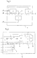
- FIG. 1 The drawing shows a simplified block diagram of a Meß bodinauf choirs 4 is shown, which consists of a pickup element 1 and a data storage module 5 of a fold-back circuit 2 and a memory circuit 3 and connected via three electrical lines 11, 12, 13 with an evaluation circuit, not shown is.
- the transducer element 1 represents a physical-electrical transducer, which consists for example of a strain gauge, which is applied to a deformation body.
- Such transducer elements 1 are used as a force or pressure transducer, wherein a bending stress on the deformation body is converted into an electrical resistance change, from which a force or pressure measurement is determined, displayed or further processed in an evaluation device.
- the pickup element 1 can be connected in a three-wire technique 11, 12, 13 with the evaluation device, which evaluates the electrical measurement signal by means of a measuring bridge circuit.
- Such an evaluation circuit which is connected to a strain gauge pickup element via three lines is known from DE 199 57 088 A1 known.
- two lines 11, 12 are located on the pickup element 1 at the same electrical potential.
- the two arranged directly on the transducer element 1 lines 12, 13 represent the measuring and feed lines, while the two connected to the transducer element lines 11, 12 of the same potential equal to a measuring and feed line 12 and a sensor line 11.
- the pickup element 1 is supplied with energy via the feed line 12 in the measuring operation.
- the sensor line 11 is used to detect the supply voltage to the supply and measuring line 12 with the help of the evaluation the voltage drops due to the line resistances are compensated and thus compensated.
- the line pair 11, 12 from sensor line 11 and measuring and feed line 12 for transmitting the measuring signals and for regulating the supply voltage drops used on the measuring lines.
- the measurement mode is switched to a communication mode.
- a voltage is impressed from the side of the evaluation device of the memory circuit 3 via the line pair 11, 12 from the sensor line 11 and measuring and feed line 12. Since in the conventional three-wire circuit, the sensor line 11 and the feed line 12 are connected directly in front of the pickup element, a large current would flow on these two lines, which would be limited only by the line resistances. Therefore, an electronic current limiting circuit 2 is provided in the line pair 11, 12 of the sensor line 11 and feed line 12 in front of the connection point 6 on the pickup element 1, which limits the current to a small residual current through a fold-back characteristic. Thus, here the impressed voltage is available for the supply of the memory circuit 3, whereby it switches over into the communication mode.
- the line pair 11, 12 of the sensor line 11 and feed line 12 is used for the transmission of the data from the memory circuit 3 to the evaluation device. Both the energy for feeding the memory circuit 3 and the information from the memory circuit 3 are transmitted via this line pair 11, 12.
- an integrated circuit of the manufacturer Dallas is used as memory circuit 3, which operates according to a Dallas 1-wire protocol, so that no additional lines in communication mode are needed.
- feed and measuring lines 13 may be used be separated by these by electronic switching devices in the pickup 4 of this and connected to the memory circuit 3. Also in this embodiment, no additional lines between the Meßerienaufillon 4 and the evaluation device are required for the communication mode.
- the memory content can not only be read out in the communication mode, but also be described by the evaluation device with new characteristic values and / or calibration values.
- the measured value is determined as in a measuring circuit without a data storage module 5 connected.
- No special requirements are placed on the signals in the lines 11, 12 in the measuring mode. It is only necessary to ensure that no voltage is impressed into the used sensor feed line pair 11, 12 by the evaluation electronics. This is always ensured when one of the two lines 11, 12 is connected in the measuring mode as an input signal.
- this transducer 4 with connected data storage module 5 is also suitable for carrier frequency supply and current and voltage supply with different amplitudes.
- the characteristic of the current limiting circuit 2 ensures that the measuring operation is not impaired. In this case, a certain electrical impedance of this circuit 2 in the measuring operation is not a problem, since this circuit 2 is provided in the sensor line 11 and only negligible currents occur here in the measuring operation.
- the above Meß bodinauf choir 4 with the connected data storage module 5 consists of a transducer element 1 with a strain gauge, which is connected as a quarter bridge and connected via two measuring and feed lines 12, 13 and a sensor line 11 to the evaluation device.
- the remaining supplementary resistances of the full bridge are arranged in the evaluation device and interconnected to form a full bridge with the pickup element 1.
- transducer elements 1 and four-wire circuits are known in which in addition to the measuring and feed lines 12, 13, two sensor lines 11 are provided, each of the voltage drop on one of the measuring and feed lines 12, 13 corrects. Also for such a four-wire circuit, the use of the above-described data storage module 5 as described above is possible.
- the transducer element 1 consists of several strain gauges (DMS), which is then connected as a half or full bridge.
- sensor leads 11 are provided in addition to the feed lines 12, 13, so that always a sensor feeder line pair 11, 12 can be used for connecting the data storage module 5.
- data storage modules 5 can also be used in inductive half-bridge circuits, as they are provided in Meß relienaufêtn, which are used as displacement transducers.
- the Meß bodinaufillon 4 may be formed as a temperature sensor, in which the physical-electrical transducer elements consist of temperature-sensitive resistors, which are connected as a Wheatstone bridge. These circuits also require to compensate for the voltage drop on the connecting lines between the sensor element 1 and the evaluation device via Sensor lines 11 which can be used in conjunction with a feed line for connecting the data storage module 5.
- thermocouple such temperature sensors can also be formed with a thermocouple, wherein only one line pair is required between the evaluation device and the thermocouple. Since only a very low voltage is generated in a thermocouple, it can be assumed at the pickup element 1 of a same electrical potential, which is suitable for connecting a data storage module 5.
- the use of the above-described data storage module circuit 5 is thus possible for a plurality of pickup elements 1, so that a large part of today used analog Meßchtnaufillon can be equipped, which have a spatial distance to their evaluation and off with readable characteristic and / or calibration data storage or to be retrofitted. Especially with a digital further processing of the measuring signals in the evaluation device, the automatic reading and / or programming of such characteristic and / or calibration values is advantageous.
- Fig. 2 The drawing shows a special embodiment of the data storage module 5 is shown in the form of a simplified circuit diagram.
- a Meß Anlagennauf choir is provided, which is connected in six-wire technology 1, 2, 2 ', 3, 3', 4 with an evaluation device, not shown.
- This Meß conductingnaufillon 4 has two feed lines 2, 3, two sensor lines 2 ', 3' and two measuring lines 1, 4 which are connected to the evaluation device.
- the circuit of the data storage module 5 is provided, said pair of lines 2, 2' in the measuring mode for the compensation the bridge feed circuit of the full bridge pickup 1 is used.
- the current limiting circuit 2 of this data storage module 5 consists essentially of the IC1 as a voltage converter, a field effect transistor T1, a resistor R1, a diode D and a capacitor C1, which are connected in the sensor supply voltage pair 2 ', 2.
- the resistor R1 of about 100 ohms and the field effect transistor T1 do not interfere with the measurement operation, since the line 2 'is used as a sensor line and therefore only negligible currents flow.
- a voltage of 5 volts is now impressed in the line pair 2, 2 'from the side of the evaluation device.
- the voltage converter IC1 generates from this a negative voltage of -5 V, which switches the field-effect transistor T1 high impedance and thus limits the current according to a fold-back characteristic.
- Fig. 3 The drawing is exemplified such a fold-back curve 7 in a coordinate system.
- the current is plotted as a function of the voltage as a dotted characteristic curve 7 and the resistance as a function of the voltage as a solid curve 8 in the coordinate system.
- the current initially rises above 10 mA and drops at a switching voltage of about 4 V at a relatively constant value of 0.1 mA.
- This small residual current does not affect the supply and reading of the data memory IC2.
- the diode D and the capacitor C1 are provided so that at a momentarily reduced voltage in the line pair 2, 2 'as it occurs during data exchange with the memory circuit 3, the current limit is maintained by the high-impedance field effect transistor T1.
- the memory circuit 3 consists essentially of an integrated semiconductor device IC2, for example, from manufacturers Dallas Semiconductor is available and allows data exchange according to the Dallas 1-wire protocol.
- the semiconductor memory IC2 therefore requires only one line pair for the power supply and the data exchange and is thus likewise connected in the sensor feed line pair 2, 2 '.
- This circuit operates in the communication mode as already Fig. 1 the drawing described in detail.
Landscapes
- Physics & Mathematics (AREA)
- General Physics & Mathematics (AREA)
- Engineering & Computer Science (AREA)
- Technology Law (AREA)
- Arrangements For Transmission Of Measured Signals (AREA)
- Transition And Organic Metals Composition Catalysts For Addition Polymerization (AREA)
Claims (15)
- Enregistreur de grandeurs mesurées avec une mémoire de données branchée qui est reliée à un dispositif d'évaluation par l'intermédiaire d'au moins deux lignes de connexion (2, 2' ; 11, 12) qui ont le même potentiel électrique en mode de mesure, dans lequel les données prédéterminées par le dispositif d'évaluation peuvent être extraites et/ou écrites hors de la mémoire de données (3), caractérisé en ce que la mémoire de données (3) est conçue comme un module de mémoire de données (5) qui est raccordé à une paire de lignes (2, 2' ; 11, 12) avec le même ou pratiquement le même potentiel électrique en mode de mesure et qui peut être commuté entre le mode de mesure et un mode de communication pour le transfert de données par un circuit électronique limiteur de courant (2) dans le module de mémoire de données (5).
- Enregistreur de grandeurs mesurées selon la revendication 1, caractérisé en ce que le module de mémoire de données (5) contient un circuit électronique limiteur de courant (2) et une mémoire de données (3) pour l'extraction et/ou la saisie de données d'identification et/ou d'étalonnage prédéterminables.
- Enregistreur de grandeurs mesurées selon la revendication 1 ou 2, caractérisé en ce que, pour la conversion physique-électrique, il est prévu au moins un élément enregistreur (1) qui forme une unité modulaire avec le module de mémoire de données (5) ou qui est disposé à proximité de celui-ci.
- Enregistreur de grandeurs mesurées selon l'une quelconque des revendications précédentes, caractérisé en ce que l'élément enregistreur (1) est prévu avec des extensomètres à fil d'acier (DMS) ou d'autres résistances variables pour la conversion physique-électrique qui sont montés comme un pont de Wheatstone et qui sont connectés au dispositif d'évaluation par trois, quatre, cinq ou six lignes (1, 2, 2', 3, 3', 4 ; 11, 12, 13).
- Enregistreur de grandeurs mesurées selon l'une quelconque des revendications 1 à 3, caractérisé en ce que l'élément enregistreur (1) est conçu comme thermocouple ou comme enregistreur inductif qui est connecté au dispositif d'évaluation par au moins deux lignes.
- Enregistreur de grandeurs mesurées selon l'une quelconque des revendications précédentes, caractérisé en ce que le circuit électronique limiteur de courant (2) est conçu de telle manière qu'une commutation en limitation de courant résiduel suivant une courbe caractéristique Fold-Back (7), qui représente un mode de communication, est réalisée par une tension appliquée à la paire de lignes (2, 2' ; 11, 12) avec le même potentiel électrique du côté du dispositif d'évaluation.
- Enregistreur de grandeurs mesurées selon l'une quelconque des revendications précédentes, caractérisé en ce que, en mode de communication, les données stockées dans la mémoire de données (3) peuvent être extraites et/ou de nouvelles données peuvent être saisies du côté du dispositif d'évaluation.
- Enregistreur de grandeurs mesurées selon l'une quelconque des revendications précédentes, caractérisé en ce que le circuit électronique limiteur de courant (2) comprend au moins un convertisseur de tension (IC1), un transistor à effet de champ (T1), une résistance (R1), une diode (D) et un condensateur (C1) qui sont montés dans une ligne de détection (2', 11) ou dans une ligne de mesure hors tension.
- Enregistreur de grandeurs mesurées selon l'une quelconque des revendications précédentes, caractérisé en ce que la mémoire de données (3) est constituée par un circuit de commutation intégré (IC2) qui est conçu de telle manière que le transfert de données se fait suivant le protocole Dallas-1-wire.
- Enregistreur de grandeurs mesurées selon l'une quelconque des revendications précédentes, caractérisé en ce que les lignes (2, 2', 11, 12) pour la commutation en mode de communication et pour l'échange de données pendant le mode de mesure sont prévues, en même temps, pour l'alimentation de l'élément enregistreur (1) et/ou pour la détection des valeurs mesurées.
- Enregistreur de grandeurs mesurées selon l'une quelconque des revendications précédentes, caractérisé en ce que l'enregistreur avec mémoire de données (3) suivant la technique à trois, quatre, cinq et six conducteurs est équipé du même nombre de lignes de connexion (1, 2, 2', 3, 3', 4 ; 11, 12, 13) qu'un enregistreur courant sans mémoire de données.
- Procédé pour le détection de données mesurées et pour l'échange de données avec un enregistreur de grandeurs mesurées selon l'une quelconque des revendications 1 à 10, caractérisé en ce que, pour la commutation entre un mode de mesure et un mode de communication, une tension est appliquée à une paire de lignes de connexion (2, 2' ; 11, 12) avec le même potentiel électrique entre un enregistreur (4) et un dispositif d'évaluation, grâce à laquelle le courant est limité à un faible courant résiduel (7) et qui est maintenu pendant l'échange de données, la paire de lignes de connexion (2, 2' ; 11, 12) servant à l'alimentation et/ou au transfert de données mesurées en mode de mesure.
- Procédé selon la revendication 12, caractérisé en ce que, pour la commutation en mode de communication et pour le transfert de données, on utilise une paire de lignes de connexion (2, 2' ; 11, 12) qui est également nécessaire pour la détection et/ou pour l'alimentation des valeurs mesurées dans des circuits conventionnels suivant la technique à deux, trois, quatre, cinq ou six conducteurs pour la connexion de l'enregistreur (4) et du circuit d'évaluation.
- Procédé selon l'une quelconque des revendications 12 ou 13, caractérisé en ce que l'enregistreur de données mesurées (4) est alimenté avec une tension continue, un courant continu, une tension à fréquence porteuse ou un courant à fréquence porteuse.
- Procédé selon l'une quelconque des revendications 12 à 14, caractérisé en ce que plusieurs enregistreurs de données mesurées (4) avec module de mémoire de données (5) sont montés en parallèle et les données des différents modules de mémoire de données (5) sont extraites par un dispositif d'évaluation commun.
Applications Claiming Priority (3)
| Application Number | Priority Date | Filing Date | Title |
|---|---|---|---|
| DE10130215 | 2001-06-22 | ||
| DE10130215A DE10130215B4 (de) | 2001-06-22 | 2001-06-22 | Meßgrößenaufnehmer mit angeschlossenem Datenspeicher |
| PCT/EP2002/006836 WO2003001155A2 (fr) | 2001-06-22 | 2002-06-20 | Transducteur avec memoire de donnees raccordee |
Publications (2)
| Publication Number | Publication Date |
|---|---|
| EP1399713A2 EP1399713A2 (fr) | 2004-03-24 |
| EP1399713B1 true EP1399713B1 (fr) | 2008-02-13 |
Family
ID=7689123
Family Applications (1)
| Application Number | Title | Priority Date | Filing Date |
|---|---|---|---|
| EP02758254A Expired - Lifetime EP1399713B1 (fr) | 2001-06-22 | 2002-06-20 | Transducteur avec memoire de donnees raccordee |
Country Status (5)
| Country | Link |
|---|---|
| US (1) | US7016792B2 (fr) |
| EP (1) | EP1399713B1 (fr) |
| AT (1) | ATE386254T1 (fr) |
| DE (2) | DE10130215B4 (fr) |
| WO (1) | WO2003001155A2 (fr) |
Families Citing this family (10)
| Publication number | Priority date | Publication date | Assignee | Title |
|---|---|---|---|---|
| DE102006001084B4 (de) * | 2006-01-03 | 2009-09-03 | Imc Messsysteme Gmbh | Messgrößenerfassungseinrichtung und Verfahren zum Erfassen von Messgrößen |
| US8175835B2 (en) | 2006-05-17 | 2012-05-08 | Honeywell International Inc. | Flow sensor with conditioning-coefficient memory |
| US8010322B2 (en) * | 2006-05-17 | 2011-08-30 | Honeywell International Inc. | Signal conditioning IC with conditioning-coefficient memory |
| DE102006039295A1 (de) * | 2006-08-22 | 2008-03-13 | Knorr-Bremse Systeme für Nutzfahrzeuge GmbH | Anordnung zum Betrieb eines Sensors |
| EP1947422B1 (fr) * | 2007-01-19 | 2011-11-23 | SICK STEGMANN GmbH | Procédé et appareil pour paramétrer un dispositif de mesure |
| DE102007012992B3 (de) * | 2007-03-14 | 2008-08-14 | Imc Messsysteme Gmbh | Messgrößenerfassungseinrichtung, Messgrößenerfassungssystem und Verfahren zum Erfassen von Messgrößen und Ansprechen einer aktivierbaren Schaltungseinheit |
| DE102008034318B4 (de) * | 2008-07-23 | 2019-08-29 | Robert Bosch Gmbh | Anordnung zur Auswertung der Messwerte eines Messwertwandlers |
| US8718981B2 (en) | 2011-05-09 | 2014-05-06 | Honeywell International Inc. | Modular sensor assembly including removable sensing module |
| DE102012007776B4 (de) | 2012-04-25 | 2014-06-26 | Brüel & Kjaer Vibro GmbH | Eindraht-Programmier- und Messkette |
| DE102012014584A1 (de) | 2012-07-23 | 2014-01-23 | Hottinger Baldwin Messtechnik Gmbh | Messgrößenaufnehmer mit internem Datenspeicher |
Family Cites Families (20)
| Publication number | Priority date | Publication date | Assignee | Title |
|---|---|---|---|---|
| DE2302024C3 (de) | 1973-01-16 | 1978-07-27 | Siemens Ag, 1000 Berlin Und 8000 Muenchen | Schaltungsanordnung zum Anschließen von Telegrafie- und Datenteilnehmern an eine Vermittlungsanlage |
| DE3446248A1 (de) * | 1984-12-19 | 1986-06-19 | Robert Bosch Gmbh, 7000 Stuttgart | Sensor zur messung physikalischer groessen und verfahren zum abgleich des sensors |
| DE3535642A1 (de) * | 1985-10-05 | 1986-07-03 | Mtu Motoren- Und Turbinen-Union Friedrichshafen Gmbh, 7990 Friedrichshafen | Einrichtung zur korrektur von messwerten |
| DE3743846A1 (de) * | 1987-12-23 | 1989-07-13 | Porsche Ag | Messwertaufnehmer |
| DE4024402C1 (fr) * | 1990-08-01 | 1991-10-31 | Dr.Ing.H.C. F. Porsche Ag, 7000 Stuttgart, De | |
| DE4114073C3 (de) * | 1991-04-30 | 2001-07-05 | Bosch Gmbh Robert | Schaltungsanordnung zur Stabilisierung einer Spannung |
| DE4114921A1 (de) * | 1991-05-07 | 1992-11-12 | Ahlborn Mess Und Regelungstech | Elektrische steckverbindung |
| DE4129577C2 (de) * | 1991-09-06 | 1999-11-25 | Mueller Arnold Gmbh Co Kg | Meßsystem zur Drehwinkelmessung |
| DE29521356U1 (de) * | 1994-10-12 | 1997-01-02 | Sega Enterprises Kk | Verbesserung der Kommunikation zwischen einer Datenverarbeitungsvorrichtung und deren Peripheriegerät |
| DE29521924U1 (de) * | 1995-11-24 | 1998-10-15 | Prüftechnik Dieter Busch AG, 85737 Ismaning | Vorrichtung zum Erzeugen und Verarbeiten von Meßsignalen |
| US5940510A (en) * | 1996-01-31 | 1999-08-17 | Dallas Semiconductor Corporation | Transfer of valuable information between a secure module and another module |
| DE19621375A1 (de) * | 1996-05-28 | 1997-12-04 | Sartorius Gmbh | Elektronische Waage nach dem Prinzip der elektromagnetischen Kraftkompensation |
| US5805466A (en) | 1996-11-27 | 1998-09-08 | Motorola Inc. | Device and method for calibrating a signal |
| DE19707708C2 (de) * | 1997-02-26 | 2002-01-10 | Infineon Technologies Ag | Strombegrenzungsschaltung |
| EP0926470A4 (fr) * | 1997-07-14 | 2005-06-15 | Matsushita Electric Industrial Co Ltd | Capteur dote d'une fonction de reglage |
| NZ505099A (en) | 1997-11-20 | 2002-03-01 | Weyerhaeuser Co | Nutritive media and manufactured seeds comprising same |
| US6239732B1 (en) * | 1998-04-13 | 2001-05-29 | Dallas Semiconductor Corporation | One-wire device with A-to-D converter |
| DE19856090C1 (de) * | 1998-12-04 | 2000-07-06 | Pcs Process Control Systems Gm | Vorrichtung zur Meßsignalvorverarbeitung für eine speicherprogrammierte Steuerung (SPS) |
| DE19957088A1 (de) * | 1999-11-29 | 2001-05-31 | Hbm Mes Und Systemtechnik Gmbh | Messbrückenschaltung in Dreileitertechnik mit Speisespannungsnachregelung |
| DE20018871U1 (de) * | 2000-11-04 | 2001-02-01 | Rheintacho Messtechnik GmbH, 79111 Freiburg | Schaltungsanordnung |
-
2001
- 2001-06-22 DE DE10130215A patent/DE10130215B4/de not_active Expired - Fee Related
-
2002
- 2002-06-20 WO PCT/EP2002/006836 patent/WO2003001155A2/fr not_active Ceased
- 2002-06-20 EP EP02758254A patent/EP1399713B1/fr not_active Expired - Lifetime
- 2002-06-20 DE DE50211683T patent/DE50211683D1/de not_active Expired - Lifetime
- 2002-06-20 AT AT02758254T patent/ATE386254T1/de not_active IP Right Cessation
- 2002-06-20 US US10/481,506 patent/US7016792B2/en not_active Expired - Fee Related
Also Published As
| Publication number | Publication date |
|---|---|
| EP1399713A2 (fr) | 2004-03-24 |
| DE50211683D1 (en) | 2008-03-27 |
| WO2003001155A2 (fr) | 2003-01-03 |
| US20040204896A1 (en) | 2004-10-14 |
| DE10130215B4 (de) | 2007-08-30 |
| ATE386254T1 (de) | 2008-03-15 |
| US7016792B2 (en) | 2006-03-21 |
| WO2003001155A3 (fr) | 2003-12-11 |
| DE10130215A1 (de) | 2003-01-02 |
Similar Documents
| Publication | Publication Date | Title |
|---|---|---|
| EP0324067B1 (fr) | Capteur | |
| EP1733410B1 (fr) | Systeme comprenant un fusible de securite pour vehicule et un convertisseur analogique/numerique | |
| DE4024402C1 (fr) | ||
| EP0892249B1 (fr) | Dispositif de mesure | |
| EP1399713B1 (fr) | Transducteur avec memoire de donnees raccordee | |
| WO2000050847A1 (fr) | Transducteur de mesure | |
| EP2035900B1 (fr) | Procédé de détermination de la résistance de charge d'un convertisseur de mesure | |
| DE102012107090A1 (de) | Mehrleitermessvorrichtung zum Erfassen eines fehlerhaften, temperaturabhängigen Widerstandssensors | |
| EP3983853B1 (fr) | Appareil de terrain de la technique de l'automatisation | |
| EP3729037B1 (fr) | Procédé permettant d'obtenir des convertisseurs de données de mesure étalonnés | |
| DE102018128305B4 (de) | Verfahren zur sensorseitigen Einstellung des vom Signaleingang einer übergeordneten Steuerungseinheit der Automatisierungstechnik erwarteten Signaltyps | |
| EP0725995B1 (fr) | Installation d'alimentation a distance | |
| EP0677721A1 (fr) | Dispositif de mesure, en particulier pour un système d'acquisition de données | |
| DE102012007776B4 (de) | Eindraht-Programmier- und Messkette | |
| DE102020133125A1 (de) | Messvorrichtung, Messsystem sowie Verwendung eines Messsystems | |
| EP2048478B1 (fr) | Procédé de reconnaissance d'un capteur à un amplificateur de mesure et d'adaptation automatique d'un amplificateur de mesure à un capteur | |
| WO2012119829A1 (fr) | Dispositif de mesure à compensation d'un mode de réponse retardé | |
| DE3433760A1 (de) | Mikroelektronisches messdaten-erfassungssystem | |
| WO2006051057A1 (fr) | Dispositif et procede de compensation pour capteurs de valeur de mesure | |
| DE102013012957A1 (de) | Sensorbauelement und Sensorschnittstelle | |
| DE102018206998A1 (de) | Informationseinstellvorrichtung und elektronisches Gerät | |
| WO2022258092A1 (fr) | Procédé d'installation et de fonctionnement d'un ensemble de mesure à points de mesure de capteurs à large répartition spatiale | |
| DE102017112755B4 (de) | Messumformerspeisegerät | |
| EP4621371A1 (fr) | Dispositif amplificateur de charge et chaîne de mesure comprenant un tel dispositif amplificateur de charge | |
| DE102008030908B4 (de) | Datenspeicherschaltung mit integrierter Datenspeichereinheit für einen Sensor mit physikalisch-elektrischem Wandler |
Legal Events
| Date | Code | Title | Description |
|---|---|---|---|
| PUAI | Public reference made under article 153(3) epc to a published international application that has entered the european phase |
Free format text: ORIGINAL CODE: 0009012 |
|
| 17P | Request for examination filed |
Effective date: 20040116 |
|
| AK | Designated contracting states |
Kind code of ref document: A2 Designated state(s): AT BE CH CY DE DK ES FI FR GB GR IE IT LI LU MC NL PT SE TR |
|
| 17Q | First examination report despatched |
Effective date: 20060913 |
|
| GRAP | Despatch of communication of intention to grant a patent |
Free format text: ORIGINAL CODE: EPIDOSNIGR1 |
|
| GRAS | Grant fee paid |
Free format text: ORIGINAL CODE: EPIDOSNIGR3 |
|
| GRAA | (expected) grant |
Free format text: ORIGINAL CODE: 0009210 |
|
| AK | Designated contracting states |
Kind code of ref document: B1 Designated state(s): AT BE CH CY DE DK ES FI FR GB GR IE IT LI LU MC NL PT SE TR |
|
| REG | Reference to a national code |
Ref country code: GB Ref legal event code: FG4D Free format text: NOT ENGLISH |
|
| REG | Reference to a national code |
Ref country code: CH Ref legal event code: EP |
|
| REG | Reference to a national code |
Ref country code: IE Ref legal event code: FG4D Free format text: LANGUAGE OF EP DOCUMENT: GERMAN |
|
| REF | Corresponds to: |
Ref document number: 50211683 Country of ref document: DE Date of ref document: 20080327 Kind code of ref document: P |
|
| GBT | Gb: translation of ep patent filed (gb section 77(6)(a)/1977) |
Effective date: 20080313 |
|
| PG25 | Lapsed in a contracting state [announced via postgrant information from national office to epo] |
Ref country code: FI Free format text: LAPSE BECAUSE OF FAILURE TO SUBMIT A TRANSLATION OF THE DESCRIPTION OR TO PAY THE FEE WITHIN THE PRESCRIBED TIME-LIMIT Effective date: 20080213 Ref country code: ES Free format text: LAPSE BECAUSE OF FAILURE TO SUBMIT A TRANSLATION OF THE DESCRIPTION OR TO PAY THE FEE WITHIN THE PRESCRIBED TIME-LIMIT Effective date: 20080524 |
|
| NLV1 | Nl: lapsed or annulled due to failure to fulfill the requirements of art. 29p and 29m of the patents act | ||
| ET | Fr: translation filed | ||
| REG | Reference to a national code |
Ref country code: IE Ref legal event code: FD4D |
|
| PG25 | Lapsed in a contracting state [announced via postgrant information from national office to epo] |
Ref country code: IE Free format text: LAPSE BECAUSE OF FAILURE TO SUBMIT A TRANSLATION OF THE DESCRIPTION OR TO PAY THE FEE WITHIN THE PRESCRIBED TIME-LIMIT Effective date: 20080213 Ref country code: NL Free format text: LAPSE BECAUSE OF FAILURE TO SUBMIT A TRANSLATION OF THE DESCRIPTION OR TO PAY THE FEE WITHIN THE PRESCRIBED TIME-LIMIT Effective date: 20080213 Ref country code: SE Free format text: LAPSE BECAUSE OF FAILURE TO SUBMIT A TRANSLATION OF THE DESCRIPTION OR TO PAY THE FEE WITHIN THE PRESCRIBED TIME-LIMIT Effective date: 20080513 Ref country code: PT Free format text: LAPSE BECAUSE OF FAILURE TO SUBMIT A TRANSLATION OF THE DESCRIPTION OR TO PAY THE FEE WITHIN THE PRESCRIBED TIME-LIMIT Effective date: 20080714 Ref country code: DK Free format text: LAPSE BECAUSE OF FAILURE TO SUBMIT A TRANSLATION OF THE DESCRIPTION OR TO PAY THE FEE WITHIN THE PRESCRIBED TIME-LIMIT Effective date: 20080213 |
|
| PLBE | No opposition filed within time limit |
Free format text: ORIGINAL CODE: 0009261 |
|
| STAA | Information on the status of an ep patent application or granted ep patent |
Free format text: STATUS: NO OPPOSITION FILED WITHIN TIME LIMIT |
|
| BERE | Be: lapsed |
Owner name: HOTTINGER BALDWIN MESSTECHNIK G.M.B.H. Effective date: 20080630 |
|
| 26N | No opposition filed |
Effective date: 20081114 |
|
| PG25 | Lapsed in a contracting state [announced via postgrant information from national office to epo] |
Ref country code: MC Free format text: LAPSE BECAUSE OF NON-PAYMENT OF DUE FEES Effective date: 20080630 |
|
| REG | Reference to a national code |
Ref country code: CH Ref legal event code: PL |
|
| PG25 | Lapsed in a contracting state [announced via postgrant information from national office to epo] |
Ref country code: BE Free format text: LAPSE BECAUSE OF NON-PAYMENT OF DUE FEES Effective date: 20080630 |
|
| PG25 | Lapsed in a contracting state [announced via postgrant information from national office to epo] |
Ref country code: LI Free format text: LAPSE BECAUSE OF NON-PAYMENT OF DUE FEES Effective date: 20080630 Ref country code: CH Free format text: LAPSE BECAUSE OF NON-PAYMENT OF DUE FEES Effective date: 20080630 |
|
| PG25 | Lapsed in a contracting state [announced via postgrant information from national office to epo] |
Ref country code: CY Free format text: LAPSE BECAUSE OF FAILURE TO SUBMIT A TRANSLATION OF THE DESCRIPTION OR TO PAY THE FEE WITHIN THE PRESCRIBED TIME-LIMIT Effective date: 20080213 |
|
| PG25 | Lapsed in a contracting state [announced via postgrant information from national office to epo] |
Ref country code: IT Free format text: LAPSE BECAUSE OF FAILURE TO SUBMIT A TRANSLATION OF THE DESCRIPTION OR TO PAY THE FEE WITHIN THE PRESCRIBED TIME-LIMIT Effective date: 20080213 Ref country code: AT Free format text: LAPSE BECAUSE OF NON-PAYMENT OF DUE FEES Effective date: 20080620 |
|
| PG25 | Lapsed in a contracting state [announced via postgrant information from national office to epo] |
Ref country code: LU Free format text: LAPSE BECAUSE OF NON-PAYMENT OF DUE FEES Effective date: 20080620 |
|
| PG25 | Lapsed in a contracting state [announced via postgrant information from national office to epo] |
Ref country code: TR Free format text: LAPSE BECAUSE OF FAILURE TO SUBMIT A TRANSLATION OF THE DESCRIPTION OR TO PAY THE FEE WITHIN THE PRESCRIBED TIME-LIMIT Effective date: 20080213 |
|
| PG25 | Lapsed in a contracting state [announced via postgrant information from national office to epo] |
Ref country code: GR Free format text: LAPSE BECAUSE OF FAILURE TO SUBMIT A TRANSLATION OF THE DESCRIPTION OR TO PAY THE FEE WITHIN THE PRESCRIBED TIME-LIMIT Effective date: 20080514 |
|
| REG | Reference to a national code |
Ref country code: DE Ref legal event code: R082 Ref document number: 50211683 Country of ref document: DE Representative=s name: SCHWEIZER, JOACHIM, DIPL.-ING., DE |
|
| REG | Reference to a national code |
Ref country code: FR Ref legal event code: PLFP Year of fee payment: 15 |
|
| REG | Reference to a national code |
Ref country code: FR Ref legal event code: PLFP Year of fee payment: 16 |
|
| REG | Reference to a national code |
Ref country code: FR Ref legal event code: PLFP Year of fee payment: 17 |
|
| PGFP | Annual fee paid to national office [announced via postgrant information from national office to epo] |
Ref country code: FR Payment date: 20190626 Year of fee payment: 18 |
|
| PGFP | Annual fee paid to national office [announced via postgrant information from national office to epo] |
Ref country code: DE Payment date: 20190624 Year of fee payment: 18 Ref country code: GB Payment date: 20190624 Year of fee payment: 18 |
|
| REG | Reference to a national code |
Ref country code: DE Ref legal event code: R082 Ref document number: 50211683 Country of ref document: DE Representative=s name: SCHWEIZER, JOACHIM, DIPL.-ING., DE Ref country code: DE Ref legal event code: R081 Ref document number: 50211683 Country of ref document: DE Owner name: HOTTINGER BRUEEL & KJAER GMBH, DE Free format text: FORMER OWNER: HOTTINGER BALDWIN MESSTECHNIK GMBH, 64293 DARMSTADT, DE |
|
| REG | Reference to a national code |
Ref country code: DE Ref legal event code: R119 Ref document number: 50211683 Country of ref document: DE |
|
| GBPC | Gb: european patent ceased through non-payment of renewal fee |
Effective date: 20200620 |
|
| PG25 | Lapsed in a contracting state [announced via postgrant information from national office to epo] |
Ref country code: GB Free format text: LAPSE BECAUSE OF NON-PAYMENT OF DUE FEES Effective date: 20200620 Ref country code: FR Free format text: LAPSE BECAUSE OF NON-PAYMENT OF DUE FEES Effective date: 20200630 |
|
| PG25 | Lapsed in a contracting state [announced via postgrant information from national office to epo] |
Ref country code: DE Free format text: LAPSE BECAUSE OF NON-PAYMENT OF DUE FEES Effective date: 20210101 |