EP1400256B1 - Beatmungsgerät - Google Patents
Beatmungsgerät Download PDFInfo
- Publication number
- EP1400256B1 EP1400256B1 EP03020719A EP03020719A EP1400256B1 EP 1400256 B1 EP1400256 B1 EP 1400256B1 EP 03020719 A EP03020719 A EP 03020719A EP 03020719 A EP03020719 A EP 03020719A EP 1400256 B1 EP1400256 B1 EP 1400256B1
- Authority
- EP
- European Patent Office
- Prior art keywords
- solenoid
- operated valve
- circuit
- controlled body
- respiration
- Prior art date
- Legal status (The legal status is an assumption and is not a legal conclusion. Google has not performed a legal analysis and makes no representation as to the accuracy of the status listed.)
- Expired - Lifetime
Links
- 210000004072 lung Anatomy 0.000 title description 3
- 230000029058 respiratory gaseous exchange Effects 0.000 claims abstract description 158
- 210000002345 respiratory system Anatomy 0.000 claims abstract description 13
- 230000000241 respiratory effect Effects 0.000 claims description 20
- 241000894006 Bacteria Species 0.000 claims description 3
- VYPSYNLAJGMNEJ-UHFFFAOYSA-N Silicium dioxide Chemical compound O=[Si]=O VYPSYNLAJGMNEJ-UHFFFAOYSA-N 0.000 claims description 3
- 239000000741 silica gel Substances 0.000 claims description 3
- 229910002027 silica gel Inorganic materials 0.000 claims description 3
- 230000005855 radiation Effects 0.000 description 19
- 238000004891 communication Methods 0.000 description 8
- 238000003384 imaging method Methods 0.000 description 6
- 210000000056 organ Anatomy 0.000 description 6
- 238000010586 diagram Methods 0.000 description 5
- 238000002591 computed tomography Methods 0.000 description 4
- 238000003745 diagnosis Methods 0.000 description 4
- 239000007789 gas Substances 0.000 description 4
- QVGXLLKOCUKJST-UHFFFAOYSA-N atomic oxygen Chemical compound [O] QVGXLLKOCUKJST-UHFFFAOYSA-N 0.000 description 2
- 238000002595 magnetic resonance imaging Methods 0.000 description 2
- 239000001301 oxygen Substances 0.000 description 2
- 229910052760 oxygen Inorganic materials 0.000 description 2
- 230000003187 abdominal effect Effects 0.000 description 1
- 210000000746 body region Anatomy 0.000 description 1
- 230000005494 condensation Effects 0.000 description 1
- 238000009833 condensation Methods 0.000 description 1
- 230000001419 dependent effect Effects 0.000 description 1
- 230000003340 mental effect Effects 0.000 description 1
- 238000000034 method Methods 0.000 description 1
- 238000002601 radiography Methods 0.000 description 1
- 229910052724 xenon Inorganic materials 0.000 description 1
- FHNFHKCVQCLJFQ-UHFFFAOYSA-N xenon atom Chemical compound [Xe] FHNFHKCVQCLJFQ-UHFFFAOYSA-N 0.000 description 1
Images



Classifications
-
- A—HUMAN NECESSITIES
- A61—MEDICAL OR VETERINARY SCIENCE; HYGIENE
- A61M—DEVICES FOR INTRODUCING MEDIA INTO, OR ONTO, THE BODY; DEVICES FOR TRANSDUCING BODY MEDIA OR FOR TAKING MEDIA FROM THE BODY; DEVICES FOR PRODUCING OR ENDING SLEEP OR STUPOR
- A61M16/00—Devices for influencing the respiratory system of patients by gas treatment, e.g. ventilators; Tracheal tubes
- A61M16/20—Valves specially adapted to medical respiratory devices
-
- A—HUMAN NECESSITIES
- A61—MEDICAL OR VETERINARY SCIENCE; HYGIENE
- A61M—DEVICES FOR INTRODUCING MEDIA INTO, OR ONTO, THE BODY; DEVICES FOR TRANSDUCING BODY MEDIA OR FOR TAKING MEDIA FROM THE BODY; DEVICES FOR PRODUCING OR ENDING SLEEP OR STUPOR
- A61M16/00—Devices for influencing the respiratory system of patients by gas treatment, e.g. ventilators; Tracheal tubes
- A61M16/20—Valves specially adapted to medical respiratory devices
- A61M16/201—Controlled valves
- A61M16/202—Controlled valves electrically actuated
- A61M16/203—Proportional
- A61M16/204—Proportional used for inhalation control
-
- A—HUMAN NECESSITIES
- A61—MEDICAL OR VETERINARY SCIENCE; HYGIENE
- A61M—DEVICES FOR INTRODUCING MEDIA INTO, OR ONTO, THE BODY; DEVICES FOR TRANSDUCING BODY MEDIA OR FOR TAKING MEDIA FROM THE BODY; DEVICES FOR PRODUCING OR ENDING SLEEP OR STUPOR
- A61M16/00—Devices for influencing the respiratory system of patients by gas treatment, e.g. ventilators; Tracheal tubes
- A61M16/20—Valves specially adapted to medical respiratory devices
- A61M16/201—Controlled valves
- A61M16/202—Controlled valves electrically actuated
- A61M16/203—Proportional
- A61M16/205—Proportional used for exhalation control
-
- A—HUMAN NECESSITIES
- A61—MEDICAL OR VETERINARY SCIENCE; HYGIENE
- A61M—DEVICES FOR INTRODUCING MEDIA INTO, OR ONTO, THE BODY; DEVICES FOR TRANSDUCING BODY MEDIA OR FOR TAKING MEDIA FROM THE BODY; DEVICES FOR PRODUCING OR ENDING SLEEP OR STUPOR
- A61M16/00—Devices for influencing the respiratory system of patients by gas treatment, e.g. ventilators; Tracheal tubes
- A61M16/10—Preparation of respiratory gases or vapours
- A61M16/105—Filters
- A61M16/1055—Filters bacterial
-
- A—HUMAN NECESSITIES
- A61—MEDICAL OR VETERINARY SCIENCE; HYGIENE
- A61M—DEVICES FOR INTRODUCING MEDIA INTO, OR ONTO, THE BODY; DEVICES FOR TRANSDUCING BODY MEDIA OR FOR TAKING MEDIA FROM THE BODY; DEVICES FOR PRODUCING OR ENDING SLEEP OR STUPOR
- A61M16/00—Devices for influencing the respiratory system of patients by gas treatment, e.g. ventilators; Tracheal tubes
- A61M16/10—Preparation of respiratory gases or vapours
- A61M16/105—Filters
- A61M16/106—Filters in a path
-
- A—HUMAN NECESSITIES
- A61—MEDICAL OR VETERINARY SCIENCE; HYGIENE
- A61M—DEVICES FOR INTRODUCING MEDIA INTO, OR ONTO, THE BODY; DEVICES FOR TRANSDUCING BODY MEDIA OR FOR TAKING MEDIA FROM THE BODY; DEVICES FOR PRODUCING OR ENDING SLEEP OR STUPOR
- A61M16/00—Devices for influencing the respiratory system of patients by gas treatment, e.g. ventilators; Tracheal tubes
- A61M16/20—Valves specially adapted to medical respiratory devices
- A61M16/208—Non-controlled one-way valves, e.g. exhalation, check, pop-off non-rebreathing valves
Definitions
- the present invention relates to a respiration control apparatus for controlling the respiration of a respiratory moving object in a controlled body such as a human body during examination or treatment.
- CT Computer-assisted diagnosis apparatus
- CR Computer-assisted Radiography
- MRI Magnetic Resonance Imaging
- radiation treatment apparatus for treating patients by applying radiation to local body regions have widely been used in the medical field.
- a respiratory moving object such as an organ in a human body to be diagnosed by a computer-assisted diagnosis apparatus or treated by a radiation treatment apparatus, changes its position or volume greatly as the human body breathes. Therefore, when the computer-assisted diagnosis apparatus images the respiratory moving object, the produced image tends to be low in quality, or when the respiratory moving object is treated by the radiation treatment apparatus, the irradiation range of radiation is liable to change.
- Japanese laid-open patent publication No. 2000-262513 discloses an X-ray computed tomographic imaging apparatus having a respiration sensor to be attached to a human body to be imaged.
- the disclosed X-ray computed tomographic imaging apparatus applies X-rays to an organ in the examinee during an inhaling period in which the volume of the organ is stable, based on an output signal from the respiration sensor, and collects image data from the organ based on the applied X-rays.
- the conventional X-ray computed tomographic imaging apparatus may not be able to collect optimum image data from a human body because the respiratory state of a human body widely differs depending on the age and the physical or mental condition of the human body. Also, the output signal from the respiration sensor widely differs depending on how the respiration sensor is attached to the human body.
- WO 99/42034 A discloses an apparatus for controlling the respiration of a human body including a device for synchronizing with physiological cycles. Specifically, this prior art device is intended to ensure that an X-ray image of the chest can be taken at peak insufflation of the patient.
- US-A-3,741,208 discloses a lung ventilator in which the lungs of a patient are connected to an overpressure source and an underpressure source via flow regulators. Each flow regulator is operated by a switching solenoid. The solenoids which are associated to the inspiration and expiration circuits are operated by a respiration cycle producer.
- a major object of the present invention is to provide a respiration control apparatus which is capable of appropriately controlling the respiration of a controlled body to increase the accuracy of an image captured by an X-ray computed tomographic imaging apparatus or the accuracy with which a radiation is applied to a local region of the controlled body by a radiation treatment apparatus.
- Specific object of the present invention is to provide a respiration control apparatus which is capable of separately controlling the inhalation and exhalation of a controlled body, and which is capable of
- FIG. 1 shows, partly in block form, a radiation image capturing system 10 to which a respiration control apparatus according to an embodiment of the present invention is applied.
- the radiation image capturing system 10 has a respiration control apparatus 14 for controlling the respiratory state of a controlled body M according to the embodiment of the present invention, a synchronizing signal generating apparatus 12 for generating a synchronizing signal based on a respiratory signal from the controlled body M, an X-ray control device 15, a high-voltage generating device 16 for generating a high voltage according to a shot signal supplied from the X-ray control device 15, a bed 17 displaceable in the direction indicated by the arrow A with the controlled body M placed thereon, an X-ray source 18 for applying X-rays to the controlled body M according to a high voltage supplied from the high-voltage generating device 16, an X-ray detector 19 for detecting X-rays that have passed through the controlled body M, a data collecting device 20 for collecting transmitted data based on X-rays detected by the X-ray detector 19, an image reconstructing device 21 for reconstructing a tomographic image of the controlled body M from transmitted data collected by the data
- the synchronizing signal generating apparatus 12 comprises a sensor signal control device 32 for producing a respiration signal indicative of a respiratory state of the controlled body M, a synchronizing signal output device 34 for outputting a synchronizing signal generated based on a respiration signal to the X-ray control device 15, and a synchronizing signal output control device 36 for controlling the timing to output a synchronizing signal.
- a laser sensor 24 fixedly disposed above the controlled body M for detecting a respiratory state of the controlled body M as a distance signal
- a load cell 26 disposed near the diaphragm or the abdominal region of the controlled body M for detecting a respiratory state of the controlled body M as a pressure signal
- a flow rate sensor 29 coupled to a mask 28 attached to the mouth of the controlled body M for detecting a respiratory state of the controlled body M as an air flow rate signal.
- FIG. 2 shows details of the sensor signal control device 32.
- the sensor signal control device 32 has amplifiers 40, 42, 44 for amplifying a distance signal supplied from the laser sensor 24, a pressure signal supplied from the load cell 26, and an air flow rate signal supplied from the air flow sensor 29, respectively.
- the sensor signal control device 32 also has a sensor selector 46 for automatically selecting sensors according to a preset priority order, a respiration signal generator 48 for converting a signal supplied from a sensor selected by the sensor selector 46 into a predetermined level, adjusting the amplitude and offset of the converted signal, and standardizing the signal so as to be independent of the type of the sensor, the individual differences of the controlled body M, and imaging conditions, thus generating a respiration signal, and a respiration signal output unit 50 for outputting a generated respiration signal to the synchronizing signal output device 34.
- a respiration signal generator 48 for converting a signal supplied from a sensor selected by the sensor selector 46 into a predetermined level, adjusting the amplitude and offset of the converted signal, and standardizing the signal so as to be independent of the type of the sensor, the individual differences of the controlled body M, and imaging conditions, thus generating a respiration signal
- a respiration signal output unit 50 for outputting a generated respiration signal to the synchronizing signal output device 34.
- FIG. 3 shows details of the synchronizing signal output device 34.
- the synchronizing signal output device 34 has a signal processor 60 to which there are connected a synchronizing signal output unit 62 for outputting a synchronizing signal to the X-ray control device 15, a respiration signal input unit 64 for being supplied with a respiration signal from the sensor signal control device 32, a synchronizing signal input unit 66 for being supplied with a synchronizing signal from the synchronizing signal output control device 36, and a respiration signal output unit 68 for outputting a respiration signal to the synchronizing signal output control device 36.
- the signal processor 60 outputs a synchronizing signal supplied from the synchronizing signal output control device 36 to the X-ray control device 15 through the synchronizing signal output unit 62.
- the signal processor 60 also calculates respiration phase data indicative of whether a respiration signal supplied from the sensor signal control device 32 represents an inhalation or an exhalation, and a maximum value of the respiration signal, and then supplies the respiration phase data and the maximum value of the respiration signal with the respiration signal, to the synchronizing signal output control device 36.
- FIG. 4 shows details of the synchronizing signal output control device 36.
- the synchronizing signal output control device 36 has a signal processor 80 to which there are connected a synchronizing signal output unit 82 for outputting a synchronizing signal to the synchronizing signal output device 34, a respiration signal input unit 84 for being supplied with a respiration signal from the synchronizing signal output device 34, and a communication processor 86 for communicating with the respiration control apparatus 14.
- An input/output device 112 having a CRT, a mouse, a keyboard, etc. is connected to the signal processor 80.
- the signal processor 80 generates a respiration control signal and a synchronizing signal from a respiration signal obtained from the synchronizing signal output device 34 through the respiration signal input unit 84 and respiration control conditions established by the input/output device 112.
- the signal processor 80 also outputs the generated respiration control signal to the respiration control apparatus 14, and outputs the synchronizing signal to the X-ray control device 15 through the synchronizing signal output device 34.
- the respiration control conditions and the respiration control signal will be described later on.
- the respiration control apparatus 14 has a respiration circuit 120 shown in FIG. 5 .
- the respiration circuit 120 basically comprises an inhalation circuit 124 (first circuit) having an inhalation inlet 121. and an inhalation outlet 122, an exhalation circuit 130 (second circuit) having an exhalation inlet 126 and an exhalation outlet 128, a first relay circuit 132 interconnecting the inhalation outlet 122 and the exhalation inlet 126, and a second relay circuit 134 interconnecting the inhalation circuit 124 near the inhalation inlet 121 and the exhalation circuit 130 near the exhalation outlet 128.
- the inhalation circuit 124 includes, successively from the inhalation inlet 121, a junction port 140 connectable to an oxygen source for supplying oxygen to the respiration circuit 120, a first solenoid-operated valve 142 for selectively connecting and disconnecting the inhalation inlet 121 and the inhalation outlet 122, and a first check valve 144 for preventing exhaled air of the controlled body M from flowing into the inhalation circuit 124.
- the exhalation circuit 130 includes, successively from the exhalation inlet 126, a vent valve 145 for connecting the exhalation circuit 130 to a forced outlet 154 when the pressure in the exhalation circuit 130 reaches a predetermined pressure, a dehumidifying chamber 146 housing a silica gel or the like for dehumidifying the interior of the exhalation circuit 130, a pressure detector 148 for detecting the pressure in the exhalation circuit 130 and outputting a signal representative of the detected pressure, a second check valve 150 for preventing air from being inhaled by the controlled body M through the exhalation circuit 130, and a second solenoid-operated valve 152 for selectively connecting and disconnecting the exhalation inlet 126 and the exhalation outlet 128.
- Each of the first solenoid-operated valve 142 and the second solenoid-operated valve 152 comprises a solenoid-operated valve which is opened when its solenoid is de-energized.
- the flow rate sensor 29 there are successively connected the flow rate sensor 29, a bacteria filter 156 for removing bacteria, and the mask 28 which is to be connected to the mouth of the controlled body M.
- the second relay circuit 134 has a third check valve 158 for preventing a gas from flowing from the exhalation circuit 130 into the inhalation circuit 124.
- the second relay circuit 134 and the third check valve 158 are added in order to provide an air flow when a xenon gas inhaling device having a closed respiration circuit, for example, is connected between the inhalation inlet 121 and the exhalation outlet 128.
- the respiration control apparatus 14 also has a central processor 160 (controller) for controlling the respiration circuit 120.
- a communication processor 162 for communicating with the synchronizing signal output control device 36
- an audio output unit 168 connected to a speaker 164 for announcing audio information and a sound level adjuster 166
- a solenoid-operated valve actuating circuit 170 for actuating the first solenoid-operated valve 142 and the second solenoid-operated valve 152
- a timer circuit 174 for actuating the first solenoid-operated valve 142 and the second solenoid-operated valve 152
- a timer circuit 174 for actuating the first solenoid-operated valve 142 and the second solenoid-operated valve 152
- a timer circuit 174 for actuating the first solenoid-operated valve 142 and the second solenoid-operated valve 152
- a timer circuit 174 for actuating the first solenoid-operated valve 142 and the second
- the respiration control apparatus 14 also has a solenoid-operated valve controller 176 which is supplied with output signals from an open switch 172 which can be operated by the controlled body M or the operator such as a doctor or the like in case of emergency, the pressure detector 148, and the timer circuit 174.
- the solenoid-operated valve controller 176 operates independently of the central processor 160 to directly control the solenoid-operated valve actuating circuit 170 based on the supplied output signals for thereby forcibly connecting the respiratory system of the controlled body M to the outside of the respiration control apparatus 14.
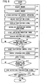
- the radiation image capturing system 10 which incorporates the respiration control apparatus 14 according to the embodiment of the present invention is basically constructed as described above. Operation of the radiation image capturing system 10 will be described below with reference to FIG. 6 .
- a sensor for acquiring a respiration signal of the controlled body M is automatically selected in step S1.
- the sensor selector 46 of the sensor signal control device 32 selects one of the sensors based on a preset priority order. For example, on the assumption that the priority order is preset according to the laser sensor 24, the flow rate sensor 29, and the load cell 26, with the priority order of the load cell 26 being lowest, if the load cell 26 is connected at all times to the sensor signal control device 32 and then the laser sensor 24 or the flow rate sensor 29 is connected to the sensor signal control device 32, then the sensor selector 46 selects the laser sensor 24 or the flow rate sensor 29.
- the laser sensor 24 or the flow rate sensor 29 may automatically be selected without removing the load cell 26.
- the selected sensor is adjusted in step S2. For example, if the laser sensor 24 is selected, the distance between the laser sensor 24 and the controlled body M is adjusted, and then laser sensor 24 is fixed in position.
- the respiration control apparatus 14 is installed in step S3. Specifically, the mask 28 is attached to the mouth of the controlled body M, and the communication processor 86 of the synchronizing signal output control device 36 and the communication processor 162 of the respiration control apparatus 14 are connected to each other by a cable or the like.
- the first solenoid-operated valve 142 and the second solenoid-operated valve 152 of the respiration control apparatus 14 are open, connecting the controlled body M to the outside of the respiration control apparatus 14 through the respiration circuit 120. Therefore, the controlled body M can freely respire.
- a gas introduced from the inhalation inlet 121 or the junction port 140 is supplied through the first solenoid-operated valve 142, the inhalation circuit 124, and the first check valve 144 as an inhalant gas to the controlled body M.
- Exhaled air from the controlled body M is discharged through the exhalation circuit 130, the second check valve 150, and the second solenoid-operated valve 152 from the exhalation outlet 128.
- the exhaled air from the controlled body M is dehumidified by the silica gel or the like housed in the dehumidifying chamber 146, thus preventing moisture condensation within the exhalation circuit 130.
- the respiratory state of the controlled body M is detected by the flow rate sensor 29, which supplies a respiration signal representative of the detected respiratory state to the sensor signal control device 32.
- the sensor signal control device 32 adjusts the amplitude and offset of the respiration signal, and standardize the respiration signal so as to make it independent of the type of the sensor, the individual properties of the controlled body M, and imaging conditions in step S4.
- the synchronizing signal output control device 36 displays the waveform of the adjusted respiration signal on the CRT of the input/output device 112 in step S5.
- the operator sets respiration control conditions based on the displayed waveform of the respiration signal in step S6.
- the respiration control conditions will be described in detail below with reference to FIG. 7 .
- the respiration control conditions includes five conditions, i.e., (1) a respiration phase condition indicative of whether the respiration control is to be started in an inhalation phase or an exhalation phase, (2) a respiration level condition indicative of which respiration level (see level "a" in FIG. 7 ) the respiration control is to be started at, (3) a respiration control time condition indicative of how long a respiration control time (see a time T1 in FIG. 7 ) is to be, (4) a synchronizing signal output delay time condition indicative of a delay time (see a time T2 in FIG.
- the radiation image capturing system 10 starts capturing a radiation image in step S7. Specifically, the operator gives an instruction to capture a radiation image from the mouse or keyboard of the input/output device 112.
- the signal processor 80 of the synchronizing signal output control device 36 transfers a control start command Q1 as a respiration control signal through the communication processor 86 to the respiration control apparatus 14.
- the central processor 160 of the respiration control apparatus 14 receives the control start command Q1 through the communication processor 162, and controls the audio output unit 168 to produce an audio guidance such as "RESPIRATION CONTROL WILL BEGIN" from the speaker 164, indicating to the controlled body M that a respiration control cycle will be started.
- the signal processor 80 of the synchronizing signal output control device 36 acquires the respiration signal indicative of the respiratory state of the controlled body M through the sensor signal control device 32 and the synchronizing signal output device 34 in step S8.
- the respiration control cycle for the control time T1 (the respiration control time condition (3)) is to be started when the respiration level at the Dth inhalation phase (the respiration phase condition (1), the respiration count condition (5)) from the control start time T0 has reached the level "a" (the respiration level condition (2)), and a synchronizing signal is outputted after elapse of the time T2 (the synchronizing signal output delay time condition (4)) from the start of the respiration control cycle.
- the signal processor 80 compares the acquired respiration signal with the respiration control conditions (1), (2), (5) set in step S6, determines whether the respiration signal satisfies the respiration control conditions (1), (2), (5) or not in step S9. If the respiration signal does not satisfy the respiration control conditions (1), (2), (5), then the signal processor 80 repeats step S9 until the respiration signal satisfies the respiration control conditions (1), (2), (5).
- step S10 If it is judged that the respiration signal satisfies the respiration control conditions (1), (2), (5), then the respiration control cycle is started in step S10.
- the signal processor 80 of the synchronizing signal output control device 36 transfers a respiration control time setting command Q2 and a respiration control start command Q3, which are respiration control signals, through the communication processor 86 to the respiration control apparatus 14.
- the central processor 160 of the respiration control apparatus 14 sets a time setting in the respiration control time setting command Q2, i.e., the time T1 shown in FIG. 7 , in a register of the time counter 177, which starts measuring time.
- the central processor 160 also sets a limit processing time T3 (T3 > T1) for the respiration control cycle in a register of the timer circuit 174, which starts measuring time.
- the limit processing time T3 is, for example, of an optimum value in an allowable limit range for the controlled body M.
- the central processor 160 controls the solenoid-operated valve actuating circuit 170 to close the first solenoid-operated valve 142 and the second solenoid-operated valve 152.
- the inhalation circuit 124 and the exhalation circuit 130 are closed, disconnecting the respiratory system of the controlled body M from the outside of the respiration control apparatus 14.
- the signal processor 80 After elapse of the time T2 (see FIG. 7 ) satisfying the synchronizing signal output delay time condition (4) after it has been judged that the respiration signal satisfies the respiration control conditions (1), (2), (5), the signal processor 80 outputs a synchronizing signal in step S11.
- the synchronizing signal generated by the signal processor 80 is supplied through the synchronizing signal output unit 82 to the synchronizing signal output device 34, and thereafter supplied from the synchronizing signal output unit 62 to the X-ray control device 15.
- the X-ray control device 15 When supplied with the synchronizing signal, the X-ray control device 15 outputs a shot signal to the high-voltage generating device 16.
- the high-voltage generating device 16 applies a high voltage to energize the X-ray source 18 to apply X rays to the controlled body M in step S12.
- the transmitted data is collected by the data collecting device 20, and then transferred to the image reconstructing device 21, which reconstructs a tomographic image of the controlled body M from the transmitted data.
- the reconstructed tomographic image is displayed by the image display device 22 for diagnosis.
- the respiration control apparatus 14 controls the controlled body M to stop its respiration. Therefore, the movement of a respiratory moving object, such as an organ in the controlled body M, is prevented. A clear reconstructed tomographic image free of artifacts is obtained.
- the signal processor 80 transfers a respiration control remaining time command Q4, which is a respiration signal, to the respiration control apparatus 14.
- the signal processor 80 may produce a plurality of respiration control remaining time commands Q4 at intervals of 5 seconds, for example, or a single respiration control remaining time command Q4, within the respiration control period.
- the central processor 160 of the respiration control apparatus 14 controls the audio output unit 168 to produce an audio guidance "REMAINING TIME OF RESPIRATION CONTROL CYCLE IS 15 SECONDS", for example, from the speaker 164, reporting the progress of the respiration control cycle successively to the controlled body M.
- the signal processor 80 transfers a respiration control cycle interrupt command through the communication processor 86 to the respiration control apparatus 14.
- the central processor 160 then performs a processing sequence based on the respiration control cycle interrupt command given the highest priority. Specifically, the central processor 160 controls the solenoid-operated valve actuating circuit 170 to open the first solenoid-operated valve 142 and the second solenoid-operated valve 152, quickly allowing the controlled body M to respire on its own.
- the signal processor 80 determines whether the respiration control time T1 has elapsed or not in step S13. If the respiration control time T1 has elapsed, then the signal processor 80 stops outputting the synchronizing signal in step S14.
- the central processor 160 of the respiration control apparatus 14 monitors a time counting end signal from the time counter 177.
- the central processor 160 controls the solenoid-operated valve actuating circuit 170 to open the first solenoid-operated valve 142 and the second solenoid-operated valve 152.
- the respiration circuit 120 is opened, canceling the stoppage of the respiration of the controlled body M and allowing the controlled body M to respire on its own.
- the central processor 160 controls the audio output unit 168 to produce an audio guidance "RESPIRATION CONTROL CYCLE IS FINISHED", for example, from the speaker 164, reporting to the controlled body M that the respiration control cycle is finished.
- the synchronizing signal generating apparatus 12 confirms whether there is a next controlled body M or not in step S15. If there is a next controlled body M to be imaged, then the operation sequence from step S1 shown in FIG. 6 is repeated. If there is none, then the operation sequence of the radiation image capturing system 10 is finished.
- the timer circuit 174 Upon elapse of the limit processing time T3 from the start of the respiration control cycle, the timer circuit 174 ends its time measuring cycle and outputs a time measuring cycle end signal to the solenoid-operated valve controller 176, independently of the process for controlling the first solenoid-operated valve 142 and the second solenoid-operated valve 152 with the central processor 160.
- the solenoid-operated valve controller 176 controls the solenoid-operated valve actuating circuit 170 to open the first solenoid-operated valve 142 and the second solenoid-operated valve 152.
- the respiration circuit 120 is opened, allowing the controlled body M to respire on its own. Consequently, even when the central processor 160 does not output a control signal to the solenoid-operated valve actuating circuit 170 to actuate first solenoid-operated valve 142 and the second solenoid-operated valve 152, the time measuring cycle end signal supplied from the timer circuit 174 enables the solenoid-operated valve controller 176 to control the solenoid-operated valve actuating circuit 170 to open the first solenoid-operated valve 142 and the second solenoid-operated valve 152.
- the pressure detector 148 detects when the pressure in the exhalation circuit 130 exceeds a predetermined pressure level, then the pressure detector 148 outputs a detected pressure signal to the solenoid-operated valve controller 176. Based on the detected pressure signal, the solenoid-operated valve controller 176 controls the solenoid-operated valve actuating circuit 170 to open the first solenoid-operated valve 142 and the second solenoid-operated valve 152. When the first solenoid-operated valve 142 and the second solenoid-operated valve 152 are opened, the respiration circuit 120 is opened, allowing the controlled body M to respire on its own.
- the open switch 172 applies an open signal to the solenoid-operated valve controller 176. Based on the open signal, the solenoid-operated valve controller 176 controls the solenoid-operated valve actuating circuit 170 to open the first solenoid-operated valve 142 and the second solenoid-operated valve 152.
- the respiration circuit 120 is opened, allowing the controlled body M to respire on its own.
- the vent valve 145 is opened, connecting the exhalation circuit 130 to the forced outlet 154.
- the controlled body M can thus breathe in the presence of the predetermined pressure in the exhalation circuit 130.
- each of the first solenoid-operated valve 142 and the second solenoid-operated valve 152 comprises a solenoid-operated valve which is opened when its solenoid is de-energized, even when a power failure occurs, for example, while the respiration control apparatus 14 is in operation, the respiration circuit 120 is opened, allowing the controlled body M to respire on its own.
Landscapes
- Health & Medical Sciences (AREA)
- Emergency Medicine (AREA)
- Pulmonology (AREA)
- Engineering & Computer Science (AREA)
- Anesthesiology (AREA)
- Biomedical Technology (AREA)
- Heart & Thoracic Surgery (AREA)
- Hematology (AREA)
- Life Sciences & Earth Sciences (AREA)
- Animal Behavior & Ethology (AREA)
- General Health & Medical Sciences (AREA)
- Public Health (AREA)
- Veterinary Medicine (AREA)
- Apparatus For Radiation Diagnosis (AREA)
- Magnetic Resonance Imaging Apparatus (AREA)
- Measurement Of The Respiration, Hearing Ability, Form, And Blood Characteristics Of Living Organisms (AREA)
- Radiation-Therapy Devices (AREA)
- Duct Arrangements (AREA)
- Percussion Or Vibration Massage (AREA)
Claims (10)
- Vorrichtung (14) zum Steuern der Atmung eines gesteuerten Körpers (M) umfassend:einen ersten Kreis (124) mit einem zum Anschließen an den gesteuerten Körper (M) ausgebildeten Ende und einem mit der Außenseite der Vorrichtung verbundenen, entgegengesetzten Ende;ein erstes Rückschlagventil (144), welches in dem ersten Kreis (124) angeordnet ist, um dem gesteuerten Körper (M) zu ermöglichen, von der Außenseite durch den ersten Kreis (124) einzuatmen und zu verhindern, dass ausgeatmete Luft aus dem gesteuerten Körper (M) in den ersten Kreis (124) strömt;ein erstes Magnetventil (142), welches in dem ersten Kreis (124) angeordnet ist, um selektiv ein Atmungssystem des gesteuerten Körpers (M) mit der Außenseite zu verbinden und von der Außenseite zu trennen;einen zweiten Kreis (130) mit einem an den gesteuerten Körper (M) angeschlossenen Ende und einem mit der Außenseite verbundenen, entgegengesetzten Ende;ein zweites Rückschlagventil (150), welches in dem zweiten Kreis (130) angeordnet ist, um dem gesteuerten Körper (M) zu ermöglichen, durch den zweiten Kreis (130) nach außen auszuatmen, und zu verhindern, dass der gesteuerte Körper (M) durch den zweiten Kreis (130) einatmet;ein zweites Magnetventil (152), welches in dem zweiten Kreis (130) angeordnet ist, um das Atmungssystem des gesteuerten Körpers (M) mit der Außenseite zu verbinden und von der Außenseite zu trennen;eine Steuerung (160) zum Steuern des ersten Magnetventils (142) und des zweiten Magnetventils (152) zu einem vorbestimmten Zeitpunkt in einem Atmungszyklus, um dadurch das Atmungssystem des gesteuerten Körpers (M) von der Außenseite zu trennen, und das erste Magnetventil (142) und das zweite Magnetventil (152) nach Verstreichen einer vorbestimmten Zeitspanne zu steuern, um dadurch das Atmungssystem des gesteuerten Körpers (M) mit der Außenseite zu verbinden,weiterhin umfassend:eine Zeitgeberschaltung (174) zum Starten der Messzeit, wenn das erste Magnetventil (142) und das zweite Magnetventil (152) begonnen haben, das Atmungssystem des gesteuerten Körpers (M) von der Außenseite zu trennen, und um einen Zeitmesszyklus-Endesignal nach Verstreichen einer vorbestimmten Zeitspanne nach dem Start der Zeitmessung auszugeben; undeine Magnetventilsteuerung (176), die auf das Zeitmesszyklus-Endesignal anspricht, um das erste Magnetventil (142) und das zweite Magnetventil (152) unabhängig von der Steuerung (160) derart zu steuern, dass das Atmungssystem des gesteuerten Körpers (M) mit der Außenseite verbunden wird.
- Vorrichtung (14) nach Anspruch 1, weiterhin umfassen.
einen Druckfühler (148) zum Nachweisen, wann ein Ausatmungsdruck in dem zweiten Kreis (130) einen vorbestimmten Druck erreicht, und um ein Drucknachweissignal auszugeben; und
eine Magnetventilsteuerung (176), die auf das Drucknachweissignal anspricht, um das erste Magnetventil (142) und das zweite Magnetventil (152) unabhängig von der Steuerung (160) so zu steuern, dass das Atmungssystem des gesteuerten Körpers (M) mit der Außenseite verbunden wird. - Vorrichtung (14) nach Anspruch 1, weiterhin umfassend:einen Öffnungsschalter (172) zum Ausgeben eines Öffnungssignals bei Betätigung; undeine Magnetventilsteuerung (176), die auf das Öffnungssignal anspricht, um das erste Magnetventil (142) und das zweite Magnetventil (152) unabhängig von der Steuerung (160) so zu steuern, dass das Atmungssystem des gesteuerten Körpers (M) mit der Außenseite verbunden wird.
- Vorrichtung (14) nach Anspruch 1, weiterhin umfassend:ein Entlüftungsventil (145), welches in den zweiten Kreis (930) angeordnet ist, um den zweiten Kreis (130) im Fall eines vorbestimmten Ausatmungsdrucks oder eines darüber liegenden Drucks in dem zweiten Kreis (130) mit der Außenseite zu verbinden.
- Vorrichtung (14) nach Anspruch 1, bei der das erste Magnetventil (142) und das zweite Magnetventil (152) das Atmungssystem des gesteuerten Körpers (M) mit der Außenseite verbinden, wenn das erste Magnetventil (142) und das zweite Magnetventil (152) abgeschaltet werden.
- Vorrichtung (14) nach Anspruch 1, weiterhin umfassend:eine Audio-Ausgabeeinheit (168) zum Ankündigen des Ablaufs eines Atmungssteuerzyklus' der Steuerung (160) mittels Sprache.
- Vorrichtung (14) nach Anspruch 1, weiterhin umfassend:einen Durchsatzfühler (29) zum Nachweisen eines Atmungszustands des gesteuerten Objekts (M) als Luftstromdurchsatz, wobei der Strömungsdurchsatzfühler (29) zwischen dem ersten Kreis (124) und dem zweiten Kreis (130) einerseits und dem gesteuerten Körper (M) andererseits, liegt;wobei die Steuerung (160) eine Einrichtung aufweist zum Steuern des ersten Magnetventils (142) und des zweiten Magnetventils (152) nach Maßgabe des erfassten Luftströmungsdurchsatzes.
- Vorrichtung (14) nach Anspruch 1, weiterhin umfassend:ein Filter (156) zum Entfernen von Bakterien, wobei das Filtern (156) zwischen dem ersten Kreis (124) und dem gesteuerten Körper (M) liegt.
- Vorrichtung (14) nach Anspruch 1, bei der der zweite Kreis (160) eine Entfeuchtungskammer (146) zum Entfeuchten von seitens des gesteuerten Körpers (M) ausgeatmeter Luft enthält.
- Vorrichtung (14) nach Anspruch 9, bei der die Entfeuchtungskammer (146) ein Kieselerdegel beinhaltet.
Applications Claiming Priority (2)
| Application Number | Priority Date | Filing Date | Title |
|---|---|---|---|
| JP2002270054A JP3691473B2 (ja) | 2002-09-17 | 2002-09-17 | 呼吸制御装置 |
| JP2002270054 | 2002-09-17 |
Publications (2)
| Publication Number | Publication Date |
|---|---|
| EP1400256A1 EP1400256A1 (de) | 2004-03-24 |
| EP1400256B1 true EP1400256B1 (de) | 2010-12-01 |
Family
ID=31944519
Family Applications (1)
| Application Number | Title | Priority Date | Filing Date |
|---|---|---|---|
| EP03020719A Expired - Lifetime EP1400256B1 (de) | 2002-09-17 | 2003-09-11 | Beatmungsgerät |
Country Status (5)
| Country | Link |
|---|---|
| US (1) | US7448381B2 (de) |
| EP (1) | EP1400256B1 (de) |
| JP (1) | JP3691473B2 (de) |
| AT (1) | ATE489983T1 (de) |
| DE (1) | DE60335165D1 (de) |
Families Citing this family (36)
| Publication number | Priority date | Publication date | Assignee | Title |
|---|---|---|---|---|
| US6937696B1 (en) * | 1998-10-23 | 2005-08-30 | Varian Medical Systems Technologies, Inc. | Method and system for predictive physiological gating |
| US7158610B2 (en) | 2003-09-05 | 2007-01-02 | Varian Medical Systems Technologies, Inc. | Systems and methods for processing x-ray images |
| US7769430B2 (en) * | 2001-06-26 | 2010-08-03 | Varian Medical Systems, Inc. | Patient visual instruction techniques for synchronizing breathing with a medical procedure |
| US7620444B2 (en) | 2002-10-05 | 2009-11-17 | General Electric Company | Systems and methods for improving usability of images for medical applications |
| EP3064242A1 (de) * | 2003-04-28 | 2016-09-07 | Advanced Circulatory Systems Inc. | Lüfter und verfahren zur behandlung von kopftrauma und geringer blutzirkulation |
| US8571639B2 (en) * | 2003-09-05 | 2013-10-29 | Varian Medical Systems, Inc. | Systems and methods for gating medical procedures |
| WO2005099382A2 (en) * | 2004-04-08 | 2005-10-27 | Virginia Commonwealth University | Four dimensional computed tomography adaptive control method and system for reducing motion artifacts and patient dose |
| US9119541B2 (en) * | 2005-08-30 | 2015-09-01 | Varian Medical Systems, Inc. | Eyewear for patient prompting |
| WO2007140478A2 (en) * | 2006-05-31 | 2007-12-06 | Masimo Corporation | Respiratory monitoring |
| JP5097406B2 (ja) * | 2007-01-22 | 2012-12-12 | ジーイー・メディカル・システムズ・グローバル・テクノロジー・カンパニー・エルエルシー | Mri装置 |
| EP2313138B1 (de) | 2008-03-31 | 2018-09-12 | Covidien LP | System und verfahren zur bestimmung von lecks in beatmungsgeräten während stabiler phasen innerhalb eines atemzugs |
| US8267085B2 (en) | 2009-03-20 | 2012-09-18 | Nellcor Puritan Bennett Llc | Leak-compensated proportional assist ventilation |
| US8272380B2 (en) | 2008-03-31 | 2012-09-25 | Nellcor Puritan Bennett, Llc | Leak-compensated pressure triggering in medical ventilators |
| US8746248B2 (en) | 2008-03-31 | 2014-06-10 | Covidien Lp | Determination of patient circuit disconnect in leak-compensated ventilatory support |
| US8251876B2 (en) | 2008-04-22 | 2012-08-28 | Hill-Rom Services, Inc. | Breathing exercise apparatus |
| US8457706B2 (en) | 2008-05-16 | 2013-06-04 | Covidien Lp | Estimation of a physiological parameter using a neural network |
| US10667727B2 (en) | 2008-09-05 | 2020-06-02 | Varian Medical Systems, Inc. | Systems and methods for determining a state of a patient |
| US8551006B2 (en) | 2008-09-17 | 2013-10-08 | Covidien Lp | Method for determining hemodynamic effects |
| US8302602B2 (en) | 2008-09-30 | 2012-11-06 | Nellcor Puritan Bennett Llc | Breathing assistance system with multiple pressure sensors |
| US8082312B2 (en) | 2008-12-12 | 2011-12-20 | Event Medical, Inc. | System and method for communicating over a network with a medical device |
| US8424521B2 (en) | 2009-02-27 | 2013-04-23 | Covidien Lp | Leak-compensated respiratory mechanics estimation in medical ventilators |
| US8418691B2 (en) | 2009-03-20 | 2013-04-16 | Covidien Lp | Leak-compensated pressure regulated volume control ventilation |
| US8789529B2 (en) | 2009-08-20 | 2014-07-29 | Covidien Lp | Method for ventilation |
| US8171094B2 (en) | 2010-01-19 | 2012-05-01 | Event Medical, Inc. | System and method for communicating over a network with a medical device |
| US8676285B2 (en) | 2010-07-28 | 2014-03-18 | Covidien Lp | Methods for validating patient identity |
| US8554298B2 (en) | 2010-09-21 | 2013-10-08 | Cividien LP | Medical ventilator with integrated oximeter data |
| US9089657B2 (en) | 2011-10-31 | 2015-07-28 | Covidien Lp | Methods and systems for gating user initiated increases in oxygen concentration during ventilation |
| US10638999B2 (en) * | 2012-02-02 | 2020-05-05 | Netspective Communications Llc | System for controlling medical devices |
| US20130204145A1 (en) * | 2012-02-02 | 2013-08-08 | Netspective Communications Llc | System and method for managing devices and data in a medical environment |
| US9180271B2 (en) | 2012-03-05 | 2015-11-10 | Hill-Rom Services Pte. Ltd. | Respiratory therapy device having standard and oscillatory PEP with nebulizer |
| US9993604B2 (en) | 2012-04-27 | 2018-06-12 | Covidien Lp | Methods and systems for an optimized proportional assist ventilation |
| US9675771B2 (en) | 2013-10-18 | 2017-06-13 | Covidien Lp | Methods and systems for leak estimation |
| US11351397B2 (en) * | 2013-10-22 | 2022-06-07 | Tel Hashomer Medical Research, Infrastructure And Services Ltd. | Apparatus for treating a target site of a body |
| JP6480598B2 (ja) | 2015-04-02 | 2019-03-13 | ヒル−ロム サービシーズ プライヴェート リミテッド | 呼吸装置用マニホールド |
| WO2017002917A1 (ja) | 2015-07-01 | 2017-01-05 | 株式会社 東芝 | 電流生成装置、電流生成装置の制御方法、動体追跡照射システム、x線照射装置、及びx線照射装置の制御方法 |
| KR101999938B1 (ko) | 2016-01-28 | 2019-07-12 | 인벤트 메디컬 코포레이션 | 흐름 발생 시스템에서의 교차오염을 방지하기 위한 시스템 및 방법 |
Citations (1)
| Publication number | Priority date | Publication date | Assignee | Title |
|---|---|---|---|---|
| WO1999042034A2 (en) * | 1998-02-20 | 1999-08-26 | University Of Florida | Device for the synchronization with physiological cycles |
Family Cites Families (14)
| Publication number | Priority date | Publication date | Assignee | Title |
|---|---|---|---|---|
| US3741208A (en) * | 1971-02-23 | 1973-06-26 | B Jonsson | Lung ventilator |
| GB1576118A (en) * | 1976-06-02 | 1980-10-01 | Boc Ltd | Lung ventilators |
| US4448192A (en) * | 1982-03-05 | 1984-05-15 | Hewlett Packard Company | Medical ventilator device parametrically controlled for patient ventilation |
| US4883051A (en) * | 1988-02-18 | 1989-11-28 | Summa Vest, Inc. | Disposable breathing system and components |
| JPH0294511A (ja) | 1988-09-30 | 1990-04-05 | Hitachi Condenser Co Ltd | 電気二重層コンデンサ |
| DE58908452D1 (de) * | 1989-01-12 | 1994-11-03 | Siemens Ag | Medizinisches Gerät zur Diagnose und/oder Therapie. |
| US5607494A (en) * | 1993-07-28 | 1997-03-04 | Kim; Young K. | Artificial soil composition and a method of growing vegetation on a sloped surface |
| US6041777A (en) * | 1995-12-01 | 2000-03-28 | Alliance Pharmaceutical Corp. | Methods and apparatus for closed-circuit ventilation therapy |
| US6003513A (en) * | 1996-01-12 | 1999-12-21 | Cochran Consulting | Rebreather having counterlung and a stepper-motor controlled variable flow rate valve |
| US6631716B1 (en) * | 1998-07-17 | 2003-10-14 | The Board Of Trustees Of The Leland Stanford Junior University | Dynamic respiratory control |
| JP2000262513A (ja) | 1999-03-15 | 2000-09-26 | Toshiba Corp | X線コンピュータ断層撮影装置 |
| SE0002805D0 (sv) * | 2000-08-01 | 2000-08-01 | Siemens Elema Ab | Pressure relief valve |
| US6910482B2 (en) * | 2001-10-19 | 2005-06-28 | Chart Inc. | Self-calibrating supplemental oxygen delivery system |
| JP3643573B2 (ja) * | 2002-06-05 | 2005-04-27 | 安西メディカル株式会社 | 放射線照射同期信号生成装置 |
-
2002
- 2002-09-17 JP JP2002270054A patent/JP3691473B2/ja not_active Expired - Lifetime
-
2003
- 2003-09-11 EP EP03020719A patent/EP1400256B1/de not_active Expired - Lifetime
- 2003-09-11 DE DE60335165T patent/DE60335165D1/de not_active Expired - Lifetime
- 2003-09-11 US US10/659,301 patent/US7448381B2/en not_active Expired - Fee Related
- 2003-09-11 AT AT03020719T patent/ATE489983T1/de not_active IP Right Cessation
Patent Citations (1)
| Publication number | Priority date | Publication date | Assignee | Title |
|---|---|---|---|---|
| WO1999042034A2 (en) * | 1998-02-20 | 1999-08-26 | University Of Florida | Device for the synchronization with physiological cycles |
Also Published As
| Publication number | Publication date |
|---|---|
| JP3691473B2 (ja) | 2005-09-07 |
| US7448381B2 (en) | 2008-11-11 |
| JP2004105359A (ja) | 2004-04-08 |
| EP1400256A1 (de) | 2004-03-24 |
| DE60335165D1 (de) | 2011-01-13 |
| ATE489983T1 (de) | 2010-12-15 |
| US20040082853A1 (en) | 2004-04-29 |
Similar Documents
| Publication | Publication Date | Title |
|---|---|---|
| US7448381B2 (en) | Respiration control apparatus | |
| JP3609111B2 (ja) | 手動換気中にフレッシュガスを供給するための装置 | |
| CN1895691B (zh) | 鼻腔供氧、特别是气流同步新生儿辅助供氧的方法和装置 | |
| US6095139A (en) | Ventilator suitable for miniaturization | |
| US6240920B1 (en) | Method for determining a parameter related to spontaneous breathing efforts by a subject, and breathing-assist apparatus operating in accordance with the method | |
| US6390091B1 (en) | Method and apparatus for controlling a medical ventilator | |
| US7257436B2 (en) | Apparatus for generating radiation application synchronizing signal | |
| US5957130A (en) | Device for compensating for flow resistance in a ventilator/respirator | |
| US7896814B2 (en) | Process and device for lung ventilation | |
| US5678540A (en) | Breathing gas system | |
| JP2553375Y2 (ja) | 医療診断装置 | |
| WO2000022985A1 (en) | Apparatus for controlled ventilation of a patient | |
| CN103153182B (zh) | 用于阻塞性睡眠呼吸暂停的诊断和治疗的系统和方法 | |
| WO2000010634A9 (en) | Apparatus and method for determining respiratory mechanics of a patient and for controlling a ventilator based thereon | |
| WO2013026902A1 (en) | Devices and methods for generating an artificial exhalation profile | |
| AU2680899A (en) | Device for the synchronization with physiological cycles | |
| US5975078A (en) | Respiratory monitoring apparatus | |
| CN111513750A (zh) | 一种适用于ct扫描的自主呼吸控制系统 | |
| EP4019071A1 (de) | Patientenbelüftungssystem mit an intubationsröhren gekoppelten sensoren und elektroden | |
| US5857459A (en) | Boxless measurement of thoracic gas volume | |
| US20140148720A1 (en) | Method and device(s) for diagnosis and/or treatment of sleep apnea and related disorders | |
| US9981095B2 (en) | Process for operating a respirator or anesthesia device in the APRV mode taking into the impedance and/or the impedance change | |
| JP6050765B2 (ja) | 中枢性無呼吸症の診断のためのシステム及び方法 | |
| KR102618686B1 (ko) | 인공호흡기를 이용한 중앙 모니터링 시스템 및 방법 | |
| JPH0938076A (ja) | X線断層画像撮影システム |
Legal Events
| Date | Code | Title | Description |
|---|---|---|---|
| PUAI | Public reference made under article 153(3) epc to a published international application that has entered the european phase |
Free format text: ORIGINAL CODE: 0009012 |
|
| AK | Designated contracting states |
Kind code of ref document: A1 Designated state(s): AT BE BG CH CY CZ DE DK EE ES FI FR GB GR HU IE IT LI LU MC NL PT RO SE SI SK TR |
|
| AX | Request for extension of the european patent |
Extension state: AL LT LV MK |
|
| 17P | Request for examination filed |
Effective date: 20040517 |
|
| AKX | Designation fees paid |
Designated state(s): AT BE BG CH CY CZ DE DK EE ES FI FR GB GR HU IE IT LI LU MC NL PT RO SE SI SK TR |
|
| 17Q | First examination report despatched |
Effective date: 20071105 |
|
| GRAP | Despatch of communication of intention to grant a patent |
Free format text: ORIGINAL CODE: EPIDOSNIGR1 |
|
| GRAS | Grant fee paid |
Free format text: ORIGINAL CODE: EPIDOSNIGR3 |
|
| GRAA | (expected) grant |
Free format text: ORIGINAL CODE: 0009210 |
|
| AK | Designated contracting states |
Kind code of ref document: B1 Designated state(s): AT BE BG CH CY CZ DE DK EE ES FI FR GB GR HU IE IT LI LU MC NL PT RO SE SI SK TR |
|
| REG | Reference to a national code |
Ref country code: GB Ref legal event code: FG4D |
|
| REG | Reference to a national code |
Ref country code: CH Ref legal event code: EP |
|
| REG | Reference to a national code |
Ref country code: IE Ref legal event code: FG4D |
|
| REF | Corresponds to: |
Ref document number: 60335165 Country of ref document: DE Date of ref document: 20110113 Kind code of ref document: P |
|
| REG | Reference to a national code |
Ref country code: SE Ref legal event code: TRGR |
|
| REG | Reference to a national code |
Ref country code: NL Ref legal event code: VDEP Effective date: 20101201 |
|
| PG25 | Lapsed in a contracting state [announced via postgrant information from national office to epo] |
Ref country code: FI Free format text: LAPSE BECAUSE OF FAILURE TO SUBMIT A TRANSLATION OF THE DESCRIPTION OR TO PAY THE FEE WITHIN THE PRESCRIBED TIME-LIMIT Effective date: 20101201 Ref country code: BG Free format text: LAPSE BECAUSE OF FAILURE TO SUBMIT A TRANSLATION OF THE DESCRIPTION OR TO PAY THE FEE WITHIN THE PRESCRIBED TIME-LIMIT Effective date: 20110301 Ref country code: AT Free format text: LAPSE BECAUSE OF FAILURE TO SUBMIT A TRANSLATION OF THE DESCRIPTION OR TO PAY THE FEE WITHIN THE PRESCRIBED TIME-LIMIT Effective date: 20101201 Ref country code: NL Free format text: LAPSE BECAUSE OF FAILURE TO SUBMIT A TRANSLATION OF THE DESCRIPTION OR TO PAY THE FEE WITHIN THE PRESCRIBED TIME-LIMIT Effective date: 20101201 Ref country code: SI Free format text: LAPSE BECAUSE OF FAILURE TO SUBMIT A TRANSLATION OF THE DESCRIPTION OR TO PAY THE FEE WITHIN THE PRESCRIBED TIME-LIMIT Effective date: 20101201 Ref country code: CY Free format text: LAPSE BECAUSE OF FAILURE TO SUBMIT A TRANSLATION OF THE DESCRIPTION OR TO PAY THE FEE WITHIN THE PRESCRIBED TIME-LIMIT Effective date: 20101201 |
|
| PG25 | Lapsed in a contracting state [announced via postgrant information from national office to epo] |
Ref country code: GR Free format text: LAPSE BECAUSE OF FAILURE TO SUBMIT A TRANSLATION OF THE DESCRIPTION OR TO PAY THE FEE WITHIN THE PRESCRIBED TIME-LIMIT Effective date: 20110302 |
|
| PG25 | Lapsed in a contracting state [announced via postgrant information from national office to epo] |
Ref country code: PT Free format text: LAPSE BECAUSE OF FAILURE TO SUBMIT A TRANSLATION OF THE DESCRIPTION OR TO PAY THE FEE WITHIN THE PRESCRIBED TIME-LIMIT Effective date: 20110401 Ref country code: BE Free format text: LAPSE BECAUSE OF FAILURE TO SUBMIT A TRANSLATION OF THE DESCRIPTION OR TO PAY THE FEE WITHIN THE PRESCRIBED TIME-LIMIT Effective date: 20101201 Ref country code: ES Free format text: LAPSE BECAUSE OF FAILURE TO SUBMIT A TRANSLATION OF THE DESCRIPTION OR TO PAY THE FEE WITHIN THE PRESCRIBED TIME-LIMIT Effective date: 20110312 Ref country code: EE Free format text: LAPSE BECAUSE OF FAILURE TO SUBMIT A TRANSLATION OF THE DESCRIPTION OR TO PAY THE FEE WITHIN THE PRESCRIBED TIME-LIMIT Effective date: 20101201 Ref country code: CZ Free format text: LAPSE BECAUSE OF FAILURE TO SUBMIT A TRANSLATION OF THE DESCRIPTION OR TO PAY THE FEE WITHIN THE PRESCRIBED TIME-LIMIT Effective date: 20101201 |
|
| PG25 | Lapsed in a contracting state [announced via postgrant information from national office to epo] |
Ref country code: RO Free format text: LAPSE BECAUSE OF FAILURE TO SUBMIT A TRANSLATION OF THE DESCRIPTION OR TO PAY THE FEE WITHIN THE PRESCRIBED TIME-LIMIT Effective date: 20101201 Ref country code: SK Free format text: LAPSE BECAUSE OF FAILURE TO SUBMIT A TRANSLATION OF THE DESCRIPTION OR TO PAY THE FEE WITHIN THE PRESCRIBED TIME-LIMIT Effective date: 20101201 |
|
| PLBE | No opposition filed within time limit |
Free format text: ORIGINAL CODE: 0009261 |
|
| STAA | Information on the status of an ep patent application or granted ep patent |
Free format text: STATUS: NO OPPOSITION FILED WITHIN TIME LIMIT |
|
| PG25 | Lapsed in a contracting state [announced via postgrant information from national office to epo] |
Ref country code: DK Free format text: LAPSE BECAUSE OF FAILURE TO SUBMIT A TRANSLATION OF THE DESCRIPTION OR TO PAY THE FEE WITHIN THE PRESCRIBED TIME-LIMIT Effective date: 20101201 |
|
| 26N | No opposition filed |
Effective date: 20110902 |
|
| PGFP | Annual fee paid to national office [announced via postgrant information from national office to epo] |
Ref country code: FR Payment date: 20111005 Year of fee payment: 9 Ref country code: SE Payment date: 20110923 Year of fee payment: 9 Ref country code: GB Payment date: 20110923 Year of fee payment: 9 |
|
| REG | Reference to a national code |
Ref country code: DE Ref legal event code: R097 Ref document number: 60335165 Country of ref document: DE Effective date: 20110902 |
|
| PG25 | Lapsed in a contracting state [announced via postgrant information from national office to epo] |
Ref country code: IT Free format text: LAPSE BECAUSE OF FAILURE TO SUBMIT A TRANSLATION OF THE DESCRIPTION OR TO PAY THE FEE WITHIN THE PRESCRIBED TIME-LIMIT Effective date: 20101201 |
|
| PG25 | Lapsed in a contracting state [announced via postgrant information from national office to epo] |
Ref country code: MC Free format text: LAPSE BECAUSE OF NON-PAYMENT OF DUE FEES Effective date: 20110930 |
|
| REG | Reference to a national code |
Ref country code: CH Ref legal event code: PL |
|
| REG | Reference to a national code |
Ref country code: IE Ref legal event code: MM4A |
|
| PG25 | Lapsed in a contracting state [announced via postgrant information from national office to epo] |
Ref country code: LI Free format text: LAPSE BECAUSE OF NON-PAYMENT OF DUE FEES Effective date: 20110930 Ref country code: IE Free format text: LAPSE BECAUSE OF NON-PAYMENT OF DUE FEES Effective date: 20110911 Ref country code: CH Free format text: LAPSE BECAUSE OF NON-PAYMENT OF DUE FEES Effective date: 20110930 |
|
| PG25 | Lapsed in a contracting state [announced via postgrant information from national office to epo] |
Ref country code: SE Free format text: LAPSE BECAUSE OF NON-PAYMENT OF DUE FEES Effective date: 20120912 |
|
| REG | Reference to a national code |
Ref country code: SE Ref legal event code: EUG |
|
| GBPC | Gb: european patent ceased through non-payment of renewal fee |
Effective date: 20120911 |
|
| PG25 | Lapsed in a contracting state [announced via postgrant information from national office to epo] |
Ref country code: LU Free format text: LAPSE BECAUSE OF NON-PAYMENT OF DUE FEES Effective date: 20110911 |
|
| REG | Reference to a national code |
Ref country code: FR Ref legal event code: ST Effective date: 20130531 |
|
| PG25 | Lapsed in a contracting state [announced via postgrant information from national office to epo] |
Ref country code: GB Free format text: LAPSE BECAUSE OF NON-PAYMENT OF DUE FEES Effective date: 20120911 |
|
| PG25 | Lapsed in a contracting state [announced via postgrant information from national office to epo] |
Ref country code: FR Free format text: LAPSE BECAUSE OF NON-PAYMENT OF DUE FEES Effective date: 20121001 |
|
| PG25 | Lapsed in a contracting state [announced via postgrant information from national office to epo] |
Ref country code: TR Free format text: LAPSE BECAUSE OF FAILURE TO SUBMIT A TRANSLATION OF THE DESCRIPTION OR TO PAY THE FEE WITHIN THE PRESCRIBED TIME-LIMIT Effective date: 20101201 |
|
| PG25 | Lapsed in a contracting state [announced via postgrant information from national office to epo] |
Ref country code: HU Free format text: LAPSE BECAUSE OF FAILURE TO SUBMIT A TRANSLATION OF THE DESCRIPTION OR TO PAY THE FEE WITHIN THE PRESCRIBED TIME-LIMIT Effective date: 20101201 |
|
| PGFP | Annual fee paid to national office [announced via postgrant information from national office to epo] |
Ref country code: DE Payment date: 20171122 Year of fee payment: 15 |
|
| REG | Reference to a national code |
Ref country code: DE Ref legal event code: R119 Ref document number: 60335165 Country of ref document: DE |
|
| PG25 | Lapsed in a contracting state [announced via postgrant information from national office to epo] |
Ref country code: DE Free format text: LAPSE BECAUSE OF NON-PAYMENT OF DUE FEES Effective date: 20190402 |