EP1400263A1 - Dämpfungsvorrichtung für ein Übungsgerät - Google Patents
Dämpfungsvorrichtung für ein Übungsgerät Download PDFInfo
- Publication number
- EP1400263A1 EP1400263A1 EP03425552A EP03425552A EP1400263A1 EP 1400263 A1 EP1400263 A1 EP 1400263A1 EP 03425552 A EP03425552 A EP 03425552A EP 03425552 A EP03425552 A EP 03425552A EP 1400263 A1 EP1400263 A1 EP 1400263A1
- Authority
- EP
- European Patent Office
- Prior art keywords
- moving part
- component
- user
- damping
- support member
- Prior art date
- Legal status (The legal status is an assumption and is not a legal conclusion. Google has not performed a legal analysis and makes no representation as to the accuracy of the status listed.)
- Granted
Links
- 238000013016 damping Methods 0.000 title claims abstract description 32
- 230000005291 magnetic effect Effects 0.000 claims abstract description 15
- 230000002596 correlated effect Effects 0.000 claims abstract description 4
- 230000009471 action Effects 0.000 claims description 6
- 230000003387 muscular Effects 0.000 claims description 4
- 238000013519 translation Methods 0.000 claims description 2
- 230000008901 benefit Effects 0.000 description 7
- 238000010276 construction Methods 0.000 description 6
- 238000000034 method Methods 0.000 description 3
- XEEYBQQBJWHFJM-UHFFFAOYSA-N Iron Chemical compound [Fe] XEEYBQQBJWHFJM-UHFFFAOYSA-N 0.000 description 2
- 238000010586 diagram Methods 0.000 description 2
- 230000000694 effects Effects 0.000 description 2
- 230000009467 reduction Effects 0.000 description 2
- 230000004044 response Effects 0.000 description 2
- 230000003068 static effect Effects 0.000 description 2
- 238000012559 user support system Methods 0.000 description 2
- RYGMFSIKBFXOCR-UHFFFAOYSA-N Copper Chemical compound [Cu] RYGMFSIKBFXOCR-UHFFFAOYSA-N 0.000 description 1
- 239000004411 aluminium Substances 0.000 description 1
- 229910052782 aluminium Inorganic materials 0.000 description 1
- XAGFODPZIPBFFR-UHFFFAOYSA-N aluminium Chemical compound [Al] XAGFODPZIPBFFR-UHFFFAOYSA-N 0.000 description 1
- 230000015572 biosynthetic process Effects 0.000 description 1
- 229910052802 copper Inorganic materials 0.000 description 1
- 239000010949 copper Substances 0.000 description 1
- 230000000875 corresponding effect Effects 0.000 description 1
- 230000001419 dependent effect Effects 0.000 description 1
- 230000002349 favourable effect Effects 0.000 description 1
- 230000005294 ferromagnetic effect Effects 0.000 description 1
- 239000003302 ferromagnetic material Substances 0.000 description 1
- 229910052742 iron Inorganic materials 0.000 description 1
- 239000000463 material Substances 0.000 description 1
- 238000005259 measurement Methods 0.000 description 1
- 229910052751 metal Inorganic materials 0.000 description 1
- 239000002184 metal Substances 0.000 description 1
- 238000012986 modification Methods 0.000 description 1
- 230000004048 modification Effects 0.000 description 1
- 230000037023 motor activity Effects 0.000 description 1
- 230000010355 oscillation Effects 0.000 description 1
- 230000021715 photosynthesis, light harvesting Effects 0.000 description 1
- 238000012549 training Methods 0.000 description 1
- 230000036642 wellbeing Effects 0.000 description 1
Images


Classifications
-
- A—HUMAN NECESSITIES
- A63—SPORTS; GAMES; AMUSEMENTS
- A63B—APPARATUS FOR PHYSICAL TRAINING, GYMNASTICS, SWIMMING, CLIMBING, OR FENCING; BALL GAMES; TRAINING EQUIPMENT
- A63B21/00—Exercising apparatus for developing or strengthening the muscles or joints of the body by working against a counterforce, with or without measuring devices
- A63B21/00192—Exercising apparatus for developing or strengthening the muscles or joints of the body by working against a counterforce, with or without measuring devices using resistance provided by magnetic means
-
- A—HUMAN NECESSITIES
- A63—SPORTS; GAMES; AMUSEMENTS
- A63B—APPARATUS FOR PHYSICAL TRAINING, GYMNASTICS, SWIMMING, CLIMBING, OR FENCING; BALL GAMES; TRAINING EQUIPMENT
- A63B21/00—Exercising apparatus for developing or strengthening the muscles or joints of the body by working against a counterforce, with or without measuring devices
-
- A—HUMAN NECESSITIES
- A63—SPORTS; GAMES; AMUSEMENTS
- A63B—APPARATUS FOR PHYSICAL TRAINING, GYMNASTICS, SWIMMING, CLIMBING, OR FENCING; BALL GAMES; TRAINING EQUIPMENT
- A63B22/00—Exercising apparatus specially adapted for conditioning the cardio-vascular system, for training agility or co-ordination of movements
- A63B22/02—Exercising apparatus specially adapted for conditioning the cardio-vascular system, for training agility or co-ordination of movements with movable endless bands, e.g. treadmills
- A63B22/0207—Exercising apparatus specially adapted for conditioning the cardio-vascular system, for training agility or co-ordination of movements with movable endless bands, e.g. treadmills having shock absorbing means
- A63B22/0214—Exercising apparatus specially adapted for conditioning the cardio-vascular system, for training agility or co-ordination of movements with movable endless bands, e.g. treadmills having shock absorbing means between the belt supporting deck and the frame
-
- A—HUMAN NECESSITIES
- A63—SPORTS; GAMES; AMUSEMENTS
- A63B—APPARATUS FOR PHYSICAL TRAINING, GYMNASTICS, SWIMMING, CLIMBING, OR FENCING; BALL GAMES; TRAINING EQUIPMENT
- A63B22/00—Exercising apparatus specially adapted for conditioning the cardio-vascular system, for training agility or co-ordination of movements
- A63B22/02—Exercising apparatus specially adapted for conditioning the cardio-vascular system, for training agility or co-ordination of movements with movable endless bands, e.g. treadmills
- A63B22/0207—Exercising apparatus specially adapted for conditioning the cardio-vascular system, for training agility or co-ordination of movements with movable endless bands, e.g. treadmills having shock absorbing means
- A63B22/0228—Exercising apparatus specially adapted for conditioning the cardio-vascular system, for training agility or co-ordination of movements with movable endless bands, e.g. treadmills having shock absorbing means with variable resilience
-
- A—HUMAN NECESSITIES
- A63—SPORTS; GAMES; AMUSEMENTS
- A63B—APPARATUS FOR PHYSICAL TRAINING, GYMNASTICS, SWIMMING, CLIMBING, OR FENCING; BALL GAMES; TRAINING EQUIPMENT
- A63B21/00—Exercising apparatus for developing or strengthening the muscles or joints of the body by working against a counterforce, with or without measuring devices
- A63B21/005—Exercising apparatus for developing or strengthening the muscles or joints of the body by working against a counterforce, with or without measuring devices using electromagnetic or electric force-resisters
-
- A—HUMAN NECESSITIES
- A63—SPORTS; GAMES; AMUSEMENTS
- A63B—APPARATUS FOR PHYSICAL TRAINING, GYMNASTICS, SWIMMING, CLIMBING, OR FENCING; BALL GAMES; TRAINING EQUIPMENT
- A63B2209/00—Characteristics of used materials
- A63B2209/08—Characteristics of used materials magnetic
Definitions
- the present invention relates to apparatuses for personal physical exercise, that is to say, to equipment, devices and machines designed for carrying out assisted motor activity for the most widespread purposes, such as recreation and fun, to achieve and maintain physical fitness and well-being, rehabilitation, gymnastics and sports training.
- the present invention relates in particular to a support device designed to dampen and cushion the mobility of a moving part of an exercise apparatus.
- support devices which basically comprise elastic supporting means and electromagnetic damping means suitably combined with one another.
- the elastic supporting means are in particular helical springs, inserted between the moving part and the fixed support member.
- the damper means consist of solenoid valves in which a ferromagnetic core, inside a tubular coil, connected to an electric circuit, under the effect of the magnetic field generated by electrically energising the coil, is moved longitudinally to the tube shape, creating a pushing or pulling action in the coil axial direction.
- damper means are connected to the moving part and to the fixed support member in such a way as to exert their action, coaxial to the coil, in series and opposing the action of the elastic means.
- the springs provide the elastic reaction to the moving part of the exercise apparatus.
- the electromagnets counteracting the latter, dampen the oscillations associated with movement of the moving part about its point of equilibrium.
- the electromagnets due to the special structural link between the electromagnets and the spring, the electromagnets being arranged in series, as indicated, the latter can influence the intrinsic rigidity of the spring, varying it.
- Adjusting means make the performance of the support device adjustable by adjusting the parameters for electrical energising of the coil. This adjustment is conveniently controlled according to input signals suitably selected amongst the system mechanical parameters, for example, the instantaneous movement of the moving part relative to a suitable reference; the force exchanged between the moving part and the user; the weight of the user, etc.
- Support devices designed in this way have the disadvantage of, generally speaking, having structures with large overall masses and which also require the presence of suspended masses whose incidence on the total masses is rather large.
- the above-mentioned structures also have large overall dimensions which affect the method used for application to the parts of the machine.
- these support devices do not have enough space to allow them to be positioned between the moving part and the fixed support member. Therefore, since the support devices have to be positioned at the side of them, they compromise machine overall dimensions in general in the direction transversal to the movement they are allowed to perform.
- a further disadvantage is the fact that the range of the damping strokes is almost the same as those allowed by conventional support devices, fitted only with elastic means, in which damping occurs only by natural energy dissipation.
- the aim of the present invention is, therefore, to overcome the above-mentioned disadvantages.
- the invention achieves said aim by providing a damping support device for an exercise apparatus, in which the apparatus comprises a moving part and a fixed support member.
- the moving part can perform movements, towards or away from the fixed support member, correlated with the exchange of forces between the user and the apparatus.
- the device comprises supporting means with at least one elastic element positioned between the moving part and the fixed support member, means for damping the movements of the moving part relative to the support member; and means for adjusting the degree of damping.
- the device is characterised in that the damping means comprise at least one magnetic actuator with a first moving component, integral with the moving part of the apparatus, and a second, fixed component, integral with the relative support member.
- Either the first or second component of the actuator has an electroconductive element designed to be the seat of an electromotive force, the other component comprising a permanent magnet and a non-permanent magnet, connected to one another in such a way as to form at least one air gap designed to radiate a magnetic field passing through the electroconductive element.
- Electrical energising of the electroconductive element produces a reactive magnetic force which, when applied to the moving component of the first and second component, counteracts its translation in the direction of the movements of the moving part of the apparatus.
- Parallel mounting of the elastic elements and the damping means allows a reduced reciprocal influence by said parts of the device, with more effective control and adjustment of the elastic reaction on one side and the damping on the other.
- the device also benefits from smaller masses, in terms of both overall masses and suspended masses, allowing: the advantage of a reduction in weights; the advantage of a more rapid device response capacity; greater possibilities for adjustment and greater versatility in terms of use of the device.
- the device made in this way is advantageously applied both in apparatuses in which the exchange of forces occurs with mainly static methods - so-called isotonic machines - and in apparatuses in which the exchange of force occurs in dynamic conditions (so-called cardio machines).
- damping means Another advantage linked mainly to the structure of the damping means is that they allow bi-directional damping, that is to say, both active and passive damping, obviously allowing a wider range of possible adjustments.
- the present invention allows a reduction of the dimensions which permits its positioning between the moving part and the fixed structure relative to which said part can move.
- the resulting overall dimensions for exercise apparatuses which use the device are not, therefore, greater than those typical of apparatuses with conventional construction.
- the numeral 1 denotes a damping support device for general use in exercise apparatuses.
- the apparatuses referred to have the most varied structures and shapes and are intended for the most general types of use: play, rehabilitation, exercise or sports. They are linked to one another by the fact that they have a moving part 2 and a support member 3, which is fixed relative to the moving part 2 and can perform movements, towards or away from the latter, correlated with the exchange of forces between the user and the apparatus while performing the various physical exercises.
- the device 1 - which can be applied in many different construction solutions, only some of which are schematically illustrated by way of example, without limiting the scope of the invention - basically comprises (see Figure 10) supporting means, labelled 4 as a whole and damping means, labelled 6 as a whole.
- the supporting means 4 comprise one or more elastic elements 5 - helical springs - operatively positioned between the moving part 2 and the fixed support member 3 of the generic exercise apparatus.
- the damping means 6 are positioned parallel with the supporting means 4 and comprise in particular a magnetic actuator, labelled 8 as a whole, which has a first, moving component 9, integral with the moving part 2 of the apparatus, and a second, fixed component, labelled 10 as a whole, integral with the relative support member 3.
- Figure 11 more clearly illustrates how the first component 9 of the actuator 8 consists of a core 40 - for example in the form of a bar attached to the moving part ( Figure 13) - which has an electroconductive element 11 designed to act as the seat of an electromotive force and which can be made according to two different construction layouts.
- the electroconductive element 11 is a coil 11.
- the coil is made using a conducting wire, preferably made of copper, which is connected to the core 40 in such a way as to form one or more loops 28, lying in a plane parallel with the axial direction 15 of the core 40 and designed so that the electric current passes through them in directions symbolically indicated in the drawing.
- the second component 10 of the actuator comprises two magnets 12 and 13 set opposite one another and on either side of the first component 9.
- the magnets are connected to one another to form a single magnetic circuit.
- one of the magnets to be precise the magnet adjacent to the first component 9, is a permanent magnet 12.
- the other, more external magnet 13 - hereinafter referred to as a non-permanent magnet - consists of a bar of ferromagnetic material, in particular soft iron, adjacent to the permanent magnet 12, side-by-side with it and further from the core 40 than the latter.
- the permanent magnet 12 (better illustrated in Figure 11) has two pairs of pole shoes 29 forming an air gap 14 housing the first, moving component 9 of the actuator 8.
- the magnetic field generated by the permanent magnet 12 and the non-permanent magnet 13 is therefore radiated in the air gap 14, reaching the coil 11 housed there.
- the coil 11 may be connected in a circuit to an electric generator of the conventional type and not illustrated, electrical energising of the coil 11 interacting with the magnetic field produces a force F which is applied to the first, moving component 9 of the actuator 8 and which can cause it to move in a direction labelled 15.
- the force F applied to the first, moving component 9 of the actuator 8 may be of different intensities (depending on the application context of the particular exercise apparatus to which the device 1 is applied, or depending on the particular use to be made of an apparatus), normally variable from one case to another and/or from one user to another of the exercise apparatus in question.
- the device 1 comprises adjusting means - visible on the right-hand side of Figure 12 and labelled 7 as a whole - which control the damping capacity of the device 1, adjusting one or more of the parameters representing coil 11 electrical energising.
- the adjusting means 7 include a control unit 30 designed to control coil 11 electrical energising, making it depend on signals 31 from the detector means 27 sensitive to variations in a suitably predetermined control parameter.
- the control parameter may be an electrical measurement, for example, the coil power supply voltage, or a physical parameter of the device, such as the electrical resistance or the number of loops in the coil.
- the adjusting means 7 may be designed, for example, in such a way as to modulate the coil 11 electric power supply voltage, according to the current position of the moving part 2 relative to the support member 3. This position is detected by the detector means 27 which, being designed and prepared specifically for this purpose, may include for example a proximity sensor suitably connected to the moving part 2.
- control may equally be made dependent on the control unit 30 receiving signals 31 carrying other types of information, such as the intensity of the force exchanged between the user and the apparatus during exercising, or signals 31 relative to the weight of the user, or directly or indirectly linked to this, or signals 31 proportional to or a function of the speed of the sliding belt, or even signals 31 obtained from a suitable combination of information relative to these variables.
- signals 31 carrying other types of information such as the intensity of the force exchanged between the user and the apparatus during exercising, or signals 31 relative to the weight of the user, or directly or indirectly linked to this, or signals 31 proportional to or a function of the speed of the sliding belt, or even signals 31 obtained from a suitable combination of information relative to these variables.
- a comparison of Figures 12 and 11 reveals that the actuator 8 may be made with at least two different construction methods.
- a first embodiment, illustrated in Figures 10 and 11 requires connection of the coil 11 to the moving component 9, whilst the permanent magnet 12 and the non-permanent magnet 13 are both connected to the fixed support member 3.
- the double air gap 14 may be used to advantage for a coil 11 with reduced height, that is to say, a smaller size in terms of the dimension detected parallel with the direction of movement 15 of the first, moving component 9. This allows the actuator 8 to be housed in a seat in the support member 3 which is correspondingly lower.
- the device 1 disclosed can easily be inserted between the moving part 2 and the support member 3 of the exercise apparatus. This allows the advantage of not influencing the overall dimensions of the exercise apparatus on which it is designed to be used.
- electroconductive elements 11 made in the form of coils through which an electric current flows, conveniently generated by an external generator, that is to say, reference is made to so-called active electroconductive elements 11.
- active electroconductive elements 11 this must not be considered a limiting factor, since equivalent and equally effective passive embodiments are also possible.
- the coil may be the seat of an induced electromotive force, caused by the movement of the first component 9 and which, opposing the movement, performs its damping action.
- the core 40 is used as the seat for formation of the induced electromotive forces.
- this may be made in the form of a monolithic aluminium element, or in the form of lamellar bars obtained by assembling a plurality of layers of metal.
- the damping may be easily adjusted by controlled variation of the size of the air gap 14 or with similar means designed to adjust some of the device 1 magnetic circuit parameters.
- the device 1 described above fulfils the aims of overcoming the disadvantages of the prior art and may be connected to many different types of exercise apparatuses, or to different parts of each apparatus.
- Observation of Figures 3 and 4 reveals how the device can be advantageously connected to a saddle 20, for example of a "bike", whose structure includes the moving part 2.
- the saddle is attached to a column 32 which in turn constitutes the support member 3.
- the saddle supports the apparatus user.
- FIG. 5 Still on the subject of methods for supporting the user, another example application is illustrated in Figure 5, where a plurality of devices 1 is attached to a seat cushion 18 and a back cushion 19 of a seat 21 of the type normally used on many exercise machines or items of equipment.
- the device 1 may also be applied to a platform 16 which in Figure 9 is represented as being applied to a structure of an exercise apparatus, only partially illustrated.
- the device 1 may be advantageously applied to a surface 17 of the type illustrated in Figure 6 which may form an elastic platform and which may be inserted structurally and operationally in a more complex machine.
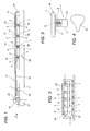
- FIGS 1 and 2 illustrate another example of application of the exercise apparatus in which a plurality of devices 1 made in accordance with the present invention are applied to an exercise apparatus - conventionally known as a "treadmill" - and as such basically equipped with a user support part, in the form of a horizontal moving surface, labelled 17 as a whole.
- the surface 17 has a sliding belt in the form of an endless flexible belt 22 looped around two rollers 34 with horizontal axes, one roller being motor-driven. The user exercises by getting onto the surface 17, walking or running on the sliding belt 22, while the belt slides at a suitable speed.
- a rigid part, in particular having the shape of a flat plate 35 is inserted between the rollers 34 and supported under the belt 22 by a plurality of supports 36 projecting from a horizontal frame 37 below.
- the supports 36 incorporate a corresponding plurality of devices 1 in which the moving component 9 of the actuator is fixed to the plate 35 above and in which the second, fixed component 10 is made integral with the horizontal frame 37.
- the devices 1 allow the belt 22 to be given an elastically yielding and dampened support so that user impact with the belt 22, or rather with the flat plate 35 below it, is more gradual and comfortable.
- Figure 7 schematically illustrates a handle 23 which can be gripped by the user of the apparatus to which the device 1 is connected in order to dampen the stroke relative to a guide and support column 38.
- Figure 8 shows how the device 1 may be positioned below a pack 39 of weights, both to dampen the impact during the downstroke, and to facilitate initial detachment during lifting.
Landscapes
- Health & Medical Sciences (AREA)
- General Health & Medical Sciences (AREA)
- Physical Education & Sports Medicine (AREA)
- Cardiology (AREA)
- Vascular Medicine (AREA)
- Life Sciences & Earth Sciences (AREA)
- Biophysics (AREA)
- Orthopedic Medicine & Surgery (AREA)
- Rehabilitation Tools (AREA)
- Vibration Prevention Devices (AREA)
- Fluid-Damping Devices (AREA)
- Vibration Dampers (AREA)
Applications Claiming Priority (2)
| Application Number | Priority Date | Filing Date | Title |
|---|---|---|---|
| IT000547A ITBO20020547A1 (it) | 2002-08-27 | 2002-08-27 | Dispositivo di supporto, con ammortizzazione, di un organo mobile di un apparato per esercizio ginnico. |
| ITBO20020547 | 2002-08-27 |
Publications (2)
| Publication Number | Publication Date |
|---|---|
| EP1400263A1 true EP1400263A1 (de) | 2004-03-24 |
| EP1400263B1 EP1400263B1 (de) | 2007-03-21 |
Family
ID=31898491
Family Applications (1)
| Application Number | Title | Priority Date | Filing Date |
|---|---|---|---|
| EP03425552A Expired - Lifetime EP1400263B1 (de) | 2002-08-27 | 2003-08-20 | Dämpfungsvorrichtung für ein Übungsgerät |
Country Status (5)
| Country | Link |
|---|---|
| US (1) | US7001312B2 (de) |
| EP (1) | EP1400263B1 (de) |
| AT (1) | ATE357277T1 (de) |
| DE (1) | DE60312618D1 (de) |
| IT (1) | ITBO20020547A1 (de) |
Cited By (5)
| Publication number | Priority date | Publication date | Assignee | Title |
|---|---|---|---|---|
| WO2011015887A1 (en) * | 2009-08-07 | 2011-02-10 | Vasileios Kelesidis | Bowl trainer |
| CN103638633A (zh) * | 2013-12-20 | 2014-03-19 | 杨鹏翔 | 跑步机路况模拟全悬浮气囊减震系统 |
| CN107648793A (zh) * | 2017-10-27 | 2018-02-02 | 石力峰 | 一种健身器材结构 |
| CN109350909A (zh) * | 2018-11-23 | 2019-02-19 | 浙江力玄运动科技股份有限公司 | 一种减震跑步机 |
| CN113750450A (zh) * | 2021-08-03 | 2021-12-07 | 宁波市康瑞达运动器材有限公司 | 一种具备随动缓冲机构的跑台升降装置及跑步机 |
Families Citing this family (20)
| Publication number | Priority date | Publication date | Assignee | Title |
|---|---|---|---|---|
| US20060160677A1 (en) | 2003-12-15 | 2006-07-20 | Bvp Holding, Inc. | Exercise apparatus |
| US7553262B2 (en) * | 2004-11-12 | 2009-06-30 | Bvp Holding, Inc. | Exercise apparatus using weights and springs for high-speed training |
| US7537550B1 (en) * | 2004-12-14 | 2009-05-26 | Krull Mark A | Exercise weight stack methods and apparatus |
| US7682294B2 (en) * | 2005-09-07 | 2010-03-23 | Bvp Holding, Inc. | Medical analysis and recording system |
| US20080161170A1 (en) * | 2006-12-20 | 2008-07-03 | Lumpee Properties, Ltd. | Magnetically guided exercise devices and systems |
| US7563205B2 (en) * | 2007-09-28 | 2009-07-21 | Johnson Health Tech. Co., Ltd. | Treadmill with cushion assembly |
| US20090221405A1 (en) * | 2008-03-03 | 2009-09-03 | Leao Wang | Shaking mechanism of a treadmill |
| GB2463729B (en) * | 2008-09-29 | 2012-10-10 | Aquarian Concept Ltd | Exercise apparatus |
| FR2950329B1 (fr) * | 2009-09-23 | 2012-08-31 | Eric Belmon | Dispositif utilisant une membrane adaptee pour porter et deplacer une charge. |
| WO2011047282A2 (en) | 2009-10-16 | 2011-04-21 | Douglas Dorsay | Exercise device and method |
| US20120270704A1 (en) * | 2011-04-21 | 2012-10-25 | Leao Wang | Cushioning mechanism for a treadmill |
| US8721504B2 (en) * | 2011-08-03 | 2014-05-13 | Leao Wang | Cushioning mechanism of a treadmill |
| TWI546103B (zh) * | 2014-12-30 | 2016-08-21 | Zhong-Fu Zhang | Treadmill of the buffer plate structure |
| US10589146B2 (en) * | 2016-05-19 | 2020-03-17 | Sara Becker | Exercise treadmill with selectable running surface |
| US10857421B2 (en) | 2017-05-31 | 2020-12-08 | Nike, Inc. | Treadmill with dynamic belt tensioning mechanism |
| US10918904B2 (en) | 2017-05-31 | 2021-02-16 | Nike, Inc. | Treadmill with vertically displaceable platform |
| CN110170149A (zh) * | 2019-06-14 | 2019-08-27 | 上海小莫网络科技有限公司 | 悬浮支撑系统和跑步机 |
| US11458356B2 (en) | 2020-02-14 | 2022-10-04 | Life Fitness, Llc | Systems and methods for adjusting a stiffness of fitness machines |
| US12337208B2 (en) | 2020-02-14 | 2025-06-24 | Life Fitness, Llc | Noise abatement for fitness machines |
| CN114432648B (zh) * | 2022-03-04 | 2023-05-30 | 浙江飞神车业有限公司 | 一种功能型跑步机及其使用方法 |
Citations (5)
| Publication number | Priority date | Publication date | Assignee | Title |
|---|---|---|---|---|
| US3464657A (en) * | 1967-08-30 | 1969-09-02 | Us Army | Vibration damped platform |
| US4849666A (en) * | 1987-12-29 | 1989-07-18 | The Charles Stark Draper Laboratory, Inc. | Electromagnetic isolator/actuator system |
| US5752879A (en) * | 1995-12-13 | 1998-05-19 | Berdut; Elberto | Tiltable multi-purpose exercise gym apparatus |
| US5993358A (en) * | 1997-03-05 | 1999-11-30 | Lord Corporation | Controllable platform suspension system for treadmill decks and the like and devices therefor |
| WO2002068066A1 (en) | 2001-02-27 | 2002-09-06 | Technogym S.P.A. | An apparatus for physical exercise with magnetic interaction between the parts of which it is made |
Family Cites Families (5)
| Publication number | Priority date | Publication date | Assignee | Title |
|---|---|---|---|---|
| US3831942A (en) * | 1973-02-13 | 1974-08-27 | Del Mar Eng Lab | Portable exercise machine |
| US5051638A (en) * | 1989-12-19 | 1991-09-24 | Nathan Pyles | Magnetically variable air resistance wheel for exercise devices |
| US5735777A (en) * | 1994-12-08 | 1998-04-07 | Kenneth J. Benoit | Adaptive weight device |
| US5711404A (en) * | 1997-02-05 | 1998-01-27 | Lee; Ying-Che | Magnetic adjustable loading device with eddy current |
| US6318517B1 (en) * | 2000-02-11 | 2001-11-20 | Huang-Tung Chang | Mechanism for effecting resistance |
-
2002
- 2002-08-27 IT IT000547A patent/ITBO20020547A1/it unknown
-
2003
- 2003-08-20 AT AT03425552T patent/ATE357277T1/de not_active IP Right Cessation
- 2003-08-20 DE DE60312618T patent/DE60312618D1/de not_active Expired - Lifetime
- 2003-08-20 EP EP03425552A patent/EP1400263B1/de not_active Expired - Lifetime
- 2003-08-22 US US10/645,586 patent/US7001312B2/en not_active Expired - Lifetime
Patent Citations (5)
| Publication number | Priority date | Publication date | Assignee | Title |
|---|---|---|---|---|
| US3464657A (en) * | 1967-08-30 | 1969-09-02 | Us Army | Vibration damped platform |
| US4849666A (en) * | 1987-12-29 | 1989-07-18 | The Charles Stark Draper Laboratory, Inc. | Electromagnetic isolator/actuator system |
| US5752879A (en) * | 1995-12-13 | 1998-05-19 | Berdut; Elberto | Tiltable multi-purpose exercise gym apparatus |
| US5993358A (en) * | 1997-03-05 | 1999-11-30 | Lord Corporation | Controllable platform suspension system for treadmill decks and the like and devices therefor |
| WO2002068066A1 (en) | 2001-02-27 | 2002-09-06 | Technogym S.P.A. | An apparatus for physical exercise with magnetic interaction between the parts of which it is made |
Cited By (9)
| Publication number | Priority date | Publication date | Assignee | Title |
|---|---|---|---|---|
| WO2011015887A1 (en) * | 2009-08-07 | 2011-02-10 | Vasileios Kelesidis | Bowl trainer |
| CN103638633A (zh) * | 2013-12-20 | 2014-03-19 | 杨鹏翔 | 跑步机路况模拟全悬浮气囊减震系统 |
| CN103638633B (zh) * | 2013-12-20 | 2016-09-07 | 杨鹏翔 | 跑步机路况模拟全悬浮气囊减震系统 |
| CN107648793A (zh) * | 2017-10-27 | 2018-02-02 | 石力峰 | 一种健身器材结构 |
| CN107648793B (zh) * | 2017-10-27 | 2018-12-04 | 绍兴市上虞区韩韩健身器材厂 | 一种健身器材结构 |
| CN109350909A (zh) * | 2018-11-23 | 2019-02-19 | 浙江力玄运动科技股份有限公司 | 一种减震跑步机 |
| CN109350909B (zh) * | 2018-11-23 | 2020-10-27 | 浙江力玄运动科技股份有限公司 | 一种减震跑步机 |
| CN113750450A (zh) * | 2021-08-03 | 2021-12-07 | 宁波市康瑞达运动器材有限公司 | 一种具备随动缓冲机构的跑台升降装置及跑步机 |
| CN113750450B (zh) * | 2021-08-03 | 2022-04-22 | 宁波市康瑞达运动器材有限公司 | 一种具备随动缓冲机构的跑台升降装置及跑步机 |
Also Published As
| Publication number | Publication date |
|---|---|
| EP1400263B1 (de) | 2007-03-21 |
| ATE357277T1 (de) | 2007-04-15 |
| US20040058786A1 (en) | 2004-03-25 |
| DE60312618D1 (de) | 2007-05-03 |
| ITBO20020547A1 (it) | 2004-02-28 |
| US7001312B2 (en) | 2006-02-21 |
Similar Documents
| Publication | Publication Date | Title |
|---|---|---|
| US7001312B2 (en) | Support device, with damping, for a mobile part of an exercise apparatus | |
| US20030148853A1 (en) | Apparatus for physical exercise with magnetic interaction between the parts of which it is made | |
| US7874963B2 (en) | Exercise device with adaptive curved track motion | |
| CA2581442C (en) | Climber mechanism | |
| KR101904909B1 (ko) | 무게추를 갖는 헬스기구 | |
| KR101025293B1 (ko) | 의자 부착용 운동기구 | |
| WO2008063051A1 (en) | Training device, training assembly and training method | |
| US20100173748A1 (en) | Electromagnetic force strength training device | |
| KR102337665B1 (ko) | 다양한 바벨운동이 가능한 헬스 운동장치 | |
| CN212941212U (zh) | 带磁流变可调阻尼的坐姿训练器 | |
| CN108578993B (zh) | 一种功率车 | |
| CN209828084U (zh) | 一种健身车 | |
| JP2015012988A (ja) | 運動用器具 | |
| KR20150061265A (ko) | 자전거형 시뮬레이터 | |
| CN210521644U (zh) | 跑步机 | |
| KR101715292B1 (ko) | 승마운동기구 | |
| ES2396852B1 (es) | Máquina de entrenamiento y valoración de la fuerza específica del kayakista con sistema dinámico de medida. | |
| KR101529874B1 (ko) | 자전거형 운동기구 | |
| KR102917374B1 (ko) | 밀림과 당김 운동 두 가지가 가능한 운동기구 | |
| KR100754428B1 (ko) | 힌지형 진동 운동기구 | |
| KR102071247B1 (ko) | 자기장을 이용한 수직 진동 운동 장치 | |
| CN218280411U (zh) | 健身设备 | |
| JPH04343861A (ja) | トレーニング機器 | |
| CN107595542A (zh) | 一种振动座椅 | |
| US20050130813A1 (en) | Exercise apparatus using weights for high-speed training |
Legal Events
| Date | Code | Title | Description |
|---|---|---|---|
| PUAI | Public reference made under article 153(3) epc to a published international application that has entered the european phase |
Free format text: ORIGINAL CODE: 0009012 |
|
| AK | Designated contracting states |
Kind code of ref document: A1 Designated state(s): AT BE BG CH CY CZ DE DK EE ES FI FR GB GR HU IE IT LI LU MC NL PT RO SE SI SK TR |
|
| AX | Request for extension of the european patent |
Extension state: AL LT LV MK |
|
| 17P | Request for examination filed |
Effective date: 20040316 |
|
| AKX | Designation fees paid |
Designated state(s): AT BE BG CH CY CZ DE DK EE ES FI FR GB GR HU IE IT LI LU MC NL PT RO SE SI SK TR |
|
| GRAP | Despatch of communication of intention to grant a patent |
Free format text: ORIGINAL CODE: EPIDOSNIGR1 |
|
| GRAS | Grant fee paid |
Free format text: ORIGINAL CODE: EPIDOSNIGR3 |
|
| GRAA | (expected) grant |
Free format text: ORIGINAL CODE: 0009210 |
|
| RAP1 | Party data changed (applicant data changed or rights of an application transferred) |
Owner name: TECHNOGYM S.P.A. |
|
| AK | Designated contracting states |
Kind code of ref document: B1 Designated state(s): AT BE BG CH CY CZ DE DK EE ES FI FR GB GR HU IE IT LI LU MC NL PT RO SE SI SK TR |
|
| PG25 | Lapsed in a contracting state [announced via postgrant information from national office to epo] |
Ref country code: LI Free format text: LAPSE BECAUSE OF FAILURE TO SUBMIT A TRANSLATION OF THE DESCRIPTION OR TO PAY THE FEE WITHIN THE PRESCRIBED TIME-LIMIT Effective date: 20070321 Ref country code: FI Free format text: LAPSE BECAUSE OF FAILURE TO SUBMIT A TRANSLATION OF THE DESCRIPTION OR TO PAY THE FEE WITHIN THE PRESCRIBED TIME-LIMIT Effective date: 20070321 Ref country code: BE Free format text: LAPSE BECAUSE OF FAILURE TO SUBMIT A TRANSLATION OF THE DESCRIPTION OR TO PAY THE FEE WITHIN THE PRESCRIBED TIME-LIMIT Effective date: 20070321 Ref country code: SI Free format text: LAPSE BECAUSE OF FAILURE TO SUBMIT A TRANSLATION OF THE DESCRIPTION OR TO PAY THE FEE WITHIN THE PRESCRIBED TIME-LIMIT Effective date: 20070321 Ref country code: AT Free format text: LAPSE BECAUSE OF FAILURE TO SUBMIT A TRANSLATION OF THE DESCRIPTION OR TO PAY THE FEE WITHIN THE PRESCRIBED TIME-LIMIT Effective date: 20070321 Ref country code: CH Free format text: LAPSE BECAUSE OF FAILURE TO SUBMIT A TRANSLATION OF THE DESCRIPTION OR TO PAY THE FEE WITHIN THE PRESCRIBED TIME-LIMIT Effective date: 20070321 Ref country code: NL Free format text: LAPSE BECAUSE OF FAILURE TO SUBMIT A TRANSLATION OF THE DESCRIPTION OR TO PAY THE FEE WITHIN THE PRESCRIBED TIME-LIMIT Effective date: 20070321 |
|
| REG | Reference to a national code |
Ref country code: GB Ref legal event code: FG4D |
|
| REG | Reference to a national code |
Ref country code: CH Ref legal event code: EP |
|
| REF | Corresponds to: |
Ref document number: 60312618 Country of ref document: DE Date of ref document: 20070503 Kind code of ref document: P |
|
| REG | Reference to a national code |
Ref country code: IE Ref legal event code: FG4D |
|
| PG25 | Lapsed in a contracting state [announced via postgrant information from national office to epo] |
Ref country code: SE Free format text: LAPSE BECAUSE OF FAILURE TO SUBMIT A TRANSLATION OF THE DESCRIPTION OR TO PAY THE FEE WITHIN THE PRESCRIBED TIME-LIMIT Effective date: 20070621 |
|
| PG25 | Lapsed in a contracting state [announced via postgrant information from national office to epo] |
Ref country code: ES Free format text: LAPSE BECAUSE OF FAILURE TO SUBMIT A TRANSLATION OF THE DESCRIPTION OR TO PAY THE FEE WITHIN THE PRESCRIBED TIME-LIMIT Effective date: 20070702 |
|
| PG25 | Lapsed in a contracting state [announced via postgrant information from national office to epo] |
Ref country code: PT Free format text: LAPSE BECAUSE OF FAILURE TO SUBMIT A TRANSLATION OF THE DESCRIPTION OR TO PAY THE FEE WITHIN THE PRESCRIBED TIME-LIMIT Effective date: 20070821 |
|
| REG | Reference to a national code |
Ref country code: CH Ref legal event code: PL |
|
| NLV1 | Nl: lapsed or annulled due to failure to fulfill the requirements of art. 29p and 29m of the patents act | ||
| EN | Fr: translation not filed | ||
| PG25 | Lapsed in a contracting state [announced via postgrant information from national office to epo] |
Ref country code: SK Free format text: LAPSE BECAUSE OF FAILURE TO SUBMIT A TRANSLATION OF THE DESCRIPTION OR TO PAY THE FEE WITHIN THE PRESCRIBED TIME-LIMIT Effective date: 20070321 |
|
| PG25 | Lapsed in a contracting state [announced via postgrant information from national office to epo] |
Ref country code: RO Free format text: LAPSE BECAUSE OF FAILURE TO SUBMIT A TRANSLATION OF THE DESCRIPTION OR TO PAY THE FEE WITHIN THE PRESCRIBED TIME-LIMIT Effective date: 20070321 Ref country code: CZ Free format text: LAPSE BECAUSE OF FAILURE TO SUBMIT A TRANSLATION OF THE DESCRIPTION OR TO PAY THE FEE WITHIN THE PRESCRIBED TIME-LIMIT Effective date: 20070321 |
|
| PLBE | No opposition filed within time limit |
Free format text: ORIGINAL CODE: 0009261 |
|
| STAA | Information on the status of an ep patent application or granted ep patent |
Free format text: STATUS: NO OPPOSITION FILED WITHIN TIME LIMIT |
|
| PG25 | Lapsed in a contracting state [announced via postgrant information from national office to epo] |
Ref country code: DE Free format text: LAPSE BECAUSE OF FAILURE TO SUBMIT A TRANSLATION OF THE DESCRIPTION OR TO PAY THE FEE WITHIN THE PRESCRIBED TIME-LIMIT Effective date: 20070622 Ref country code: DK Free format text: LAPSE BECAUSE OF FAILURE TO SUBMIT A TRANSLATION OF THE DESCRIPTION OR TO PAY THE FEE WITHIN THE PRESCRIBED TIME-LIMIT Effective date: 20070321 |
|
| 26N | No opposition filed |
Effective date: 20071227 |
|
| PG25 | Lapsed in a contracting state [announced via postgrant information from national office to epo] |
Ref country code: FR Free format text: LAPSE BECAUSE OF FAILURE TO SUBMIT A TRANSLATION OF THE DESCRIPTION OR TO PAY THE FEE WITHIN THE PRESCRIBED TIME-LIMIT Effective date: 20071123 Ref country code: GR Free format text: LAPSE BECAUSE OF FAILURE TO SUBMIT A TRANSLATION OF THE DESCRIPTION OR TO PAY THE FEE WITHIN THE PRESCRIBED TIME-LIMIT Effective date: 20070622 Ref country code: MC Free format text: LAPSE BECAUSE OF NON-PAYMENT OF DUE FEES Effective date: 20070831 |
|
| PG25 | Lapsed in a contracting state [announced via postgrant information from national office to epo] |
Ref country code: IE Free format text: LAPSE BECAUSE OF NON-PAYMENT OF DUE FEES Effective date: 20070820 |
|
| PG25 | Lapsed in a contracting state [announced via postgrant information from national office to epo] |
Ref country code: FR Free format text: LAPSE BECAUSE OF FAILURE TO SUBMIT A TRANSLATION OF THE DESCRIPTION OR TO PAY THE FEE WITHIN THE PRESCRIBED TIME-LIMIT Effective date: 20070321 |
|
| PG25 | Lapsed in a contracting state [announced via postgrant information from national office to epo] |
Ref country code: EE Free format text: LAPSE BECAUSE OF FAILURE TO SUBMIT A TRANSLATION OF THE DESCRIPTION OR TO PAY THE FEE WITHIN THE PRESCRIBED TIME-LIMIT Effective date: 20070321 |
|
| PG25 | Lapsed in a contracting state [announced via postgrant information from national office to epo] |
Ref country code: CY Free format text: LAPSE BECAUSE OF FAILURE TO SUBMIT A TRANSLATION OF THE DESCRIPTION OR TO PAY THE FEE WITHIN THE PRESCRIBED TIME-LIMIT Effective date: 20070321 |
|
| PG25 | Lapsed in a contracting state [announced via postgrant information from national office to epo] |
Ref country code: BG Free format text: LAPSE BECAUSE OF FAILURE TO SUBMIT A TRANSLATION OF THE DESCRIPTION OR TO PAY THE FEE WITHIN THE PRESCRIBED TIME-LIMIT Effective date: 20070621 Ref country code: LU Free format text: LAPSE BECAUSE OF NON-PAYMENT OF DUE FEES Effective date: 20070820 |
|
| PG25 | Lapsed in a contracting state [announced via postgrant information from national office to epo] |
Ref country code: TR Free format text: LAPSE BECAUSE OF FAILURE TO SUBMIT A TRANSLATION OF THE DESCRIPTION OR TO PAY THE FEE WITHIN THE PRESCRIBED TIME-LIMIT Effective date: 20070321 Ref country code: HU Free format text: LAPSE BECAUSE OF FAILURE TO SUBMIT A TRANSLATION OF THE DESCRIPTION OR TO PAY THE FEE WITHIN THE PRESCRIBED TIME-LIMIT Effective date: 20070922 |
|
| PGFP | Annual fee paid to national office [announced via postgrant information from national office to epo] |
Ref country code: GB Payment date: 20200825 Year of fee payment: 18 |
|
| PGFP | Annual fee paid to national office [announced via postgrant information from national office to epo] |
Ref country code: IT Payment date: 20200820 Year of fee payment: 18 |
|
| GBPC | Gb: european patent ceased through non-payment of renewal fee |
Effective date: 20210820 |
|
| PG25 | Lapsed in a contracting state [announced via postgrant information from national office to epo] |
Ref country code: IT Free format text: LAPSE BECAUSE OF NON-PAYMENT OF DUE FEES Effective date: 20210820 Ref country code: GB Free format text: LAPSE BECAUSE OF NON-PAYMENT OF DUE FEES Effective date: 20210820 |