EP1400285A2 - Zusatzvorrichtung für Farbspritzanlagen - Google Patents
Zusatzvorrichtung für Farbspritzanlagen Download PDFInfo
- Publication number
- EP1400285A2 EP1400285A2 EP20020023176 EP02023176A EP1400285A2 EP 1400285 A2 EP1400285 A2 EP 1400285A2 EP 20020023176 EP20020023176 EP 20020023176 EP 02023176 A EP02023176 A EP 02023176A EP 1400285 A2 EP1400285 A2 EP 1400285A2
- Authority
- EP
- European Patent Office
- Prior art keywords
- supply air
- ceiling
- additional device
- cabin
- filter
- Prior art date
- Legal status (The legal status is an assumption and is not a legal conclusion. Google has not performed a legal analysis and makes no representation as to the accuracy of the status listed.)
- Granted
Links
Images


Classifications
-
- F—MECHANICAL ENGINEERING; LIGHTING; HEATING; WEAPONS; BLASTING
- F26—DRYING
- F26B—DRYING SOLID MATERIALS OR OBJECTS BY REMOVING LIQUID THEREFROM
- F26B21/00—Arrangements for supplying or controlling air or other gases for drying solid materials or objects
- F26B21/003—Air or gas filters
-
- B—PERFORMING OPERATIONS; TRANSPORTING
- B05—SPRAYING OR ATOMISING IN GENERAL; APPLYING FLUENT MATERIALS TO SURFACES, IN GENERAL
- B05B—SPRAYING APPARATUS; ATOMISING APPARATUS; NOZZLES
- B05B16/00—Spray booths
- B05B16/20—Arrangements for spraying in combination with other operations, e.g. drying; Arrangements enabling a combination of spraying operations
-
- B—PERFORMING OPERATIONS; TRANSPORTING
- B05—SPRAYING OR ATOMISING IN GENERAL; APPLYING FLUENT MATERIALS TO SURFACES, IN GENERAL
- B05B—SPRAYING APPARATUS; ATOMISING APPARATUS; NOZZLES
- B05B16/00—Spray booths
- B05B16/60—Ventilation arrangements specially adapted therefor
-
- F—MECHANICAL ENGINEERING; LIGHTING; HEATING; WEAPONS; BLASTING
- F26—DRYING
- F26B—DRYING SOLID MATERIALS OR OBJECTS BY REMOVING LIQUID THEREFROM
- F26B21/00—Arrangements for supplying or controlling air or other gases for drying solid materials or objects
- F26B21/20—Circulating air or gases in closed cycles, e.g. wholly within the drying enclosure
- F26B21/25—Circulating air or gases in closed cycles, e.g. wholly within the drying enclosure partly outside the drying enclosure
-
- F—MECHANICAL ENGINEERING; LIGHTING; HEATING; WEAPONS; BLASTING
- F26—DRYING
- F26B—DRYING SOLID MATERIALS OR OBJECTS BY REMOVING LIQUID THEREFROM
- F26B21/00—Arrangements for supplying or controlling air or other gases for drying solid materials or objects
- F26B21/50—Ducting arrangements from the source of air or other gases to the materials or objects being dried
-
- B—PERFORMING OPERATIONS; TRANSPORTING
- B05—SPRAYING OR ATOMISING IN GENERAL; APPLYING FLUENT MATERIALS TO SURFACES, IN GENERAL
- B05D—PROCESSES FOR APPLYING FLUENT MATERIALS TO SURFACES, IN GENERAL
- B05D3/00—Pretreatment of surfaces to which liquids or other fluent materials are to be applied; After-treatment of applied coatings, e.g. intermediate treating of an applied coating preparatory to subsequent applications of liquids or other fluent materials
- B05D3/02—Pretreatment of surfaces to which liquids or other fluent materials are to be applied; After-treatment of applied coatings, e.g. intermediate treating of an applied coating preparatory to subsequent applications of liquids or other fluent materials by baking
- B05D3/0254—After-treatment
- B05D3/0272—After-treatment with ovens
-
- B—PERFORMING OPERATIONS; TRANSPORTING
- B05—SPRAYING OR ATOMISING IN GENERAL; APPLYING FLUENT MATERIALS TO SURFACES, IN GENERAL
- B05D—PROCESSES FOR APPLYING FLUENT MATERIALS TO SURFACES, IN GENERAL
- B05D7/00—Processes, other than flocking, specially adapted for applying liquids or other fluent materials to particular surfaces or for applying particular liquids or other fluent materials
- B05D7/14—Processes, other than flocking, specially adapted for applying liquids or other fluent materials to particular surfaces or for applying particular liquids or other fluent materials to metal, e.g. car bodies
-
- F—MECHANICAL ENGINEERING; LIGHTING; HEATING; WEAPONS; BLASTING
- F26—DRYING
- F26B—DRYING SOLID MATERIALS OR OBJECTS BY REMOVING LIQUID THEREFROM
- F26B2210/00—Drying processes and machines for solid objects characterised by the specific requirements of the drying goods
- F26B2210/12—Vehicle bodies, e.g. after being painted
Definitions
- the invention relates to an additional device according to the preamble of the claim 1.
- the sprayed objects can be accelerated by the fact that the painted Areas of high air turbulence is generated, reducing the length of stay painted objects, e.g. B. vehicle parts, reduced to a value of about 50 - 60% can be. While, for example, in conventional paint booths Air speeds directed towards the vehicle from the filter ceiling will be about 0.2 to 0.4 m / sec, will be more present for the purposes Invention air speeds in the order of 20 m / sec preferred that be directed against the vehicle parts to be dried via nozzles.
- the object of the invention is the period of time for performing the Drying process for objects painted in spray booths decisively reduce and find solutions that significantly reduce the length of stay and the effectiveness can be improved.
- Decisive for this solution according to the invention is the generation of a high one Air turbulence on the surfaces to be dried of a painted vehicle or a corresponding object so that the paint dries as quickly as possible, d. that is, excess water is removed from the paint as quickly as possible and thus the drying time of water-based paint is reduced as far as possible.
- the preheated air flow used for the drying process is over Air jets aimed specifically at the object to be dried, with a Speed or intensity which is a multiple of the air speed, with the air against the filter ceiling in conventional painting systems Vehicle is directed.
- This supply air is of high intensity and speed achieved in that air from a pressure chamber between the cabin ceiling and Filter ceiling over an additional fan, the z. B. arranged outside the cabin is sucked in and via a separate supply air duct system to the air nozzles is transported in the interior of the cabin on the side walls approximately in the area of existing lamp tubes (just above the lamps or between the lamps) are installed.
- the fan conveys the air removed from the pressure chamber closed supply air piping system or supply air duct system, e.g. B.
- the air nozzles can be optionally arranged immediately below the filter ceiling and separate from the lamp tubes and be connected to a separate, side supply air duct or on Output of a supply air pipe that separates into the lamp sections Side walls that accommodate the bracket and the connections of the lamps, be housed.
- the nozzles are preferably on the inside walls of the Cabin or, in exceptional cases, also on the inner walls of the front and rear walls installed in the cabin.
- the piping system is according to a special embodiment of the invention in Regarding the air distribution pipe system zoned so that the pipes can be switched on and off independently of each other in the individual zones can, depending on the object to be treated in the cabin. They are accordingly Pipelines connected to individual zones and others not, or the Pipelines are connected to all zones.
- the zones not required can are separated from the supply air supply by means of closures, flaps or the like, so that certain nozzles can be activated depending on the desired effect and others don't.
- the blowing direction of the nozzles can be adjusted by adjusting the Nozzle outlet opening can be changed so that the air flow in the form of Turbulence directed towards the respective object and an optimal one Effect can be achieved. Suitable nozzles are always made known in the art, so that a more detailed description of the nozzles even unnecessary.
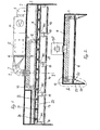
- a pressure chamber 2 is formed directly under the top wall, to which a pipe bend 3 is connected, with the outside of the painting booth 1 an additional fan 4 is connected, which receives a filter 5 and the dispensing end has an elastic connector 6, one of which Pipe elbow 7 is inserted through the cabin ceiling into the pressure chamber 2.
- the Inlet pipe opens into an air inlet duct 8, from which duct branches 9 extend, which are routed via duct bends 10, 10 'as connections into the distributor supply air duct are.
- the duct branches 9 with the duct bends 10, 10 'and Connections 12 lead the supply air into different zones 13, 14, 15, 16, which the Take lamp tubes and through the partitions and lamp holders 18, 19 are separated from each other.
- the space into which the distributor supply air duct opens is formed by the lamp boxes 25, and is designed as a pressure channel 23. This space receives the air nozzles 20, 21, 22, which the air jets 26 into the Deliver the painting area in a directed manner.
- FIGS. 4-6 corresponds in part to Representation according to Figures 1-3.
- the main difference between the two Embodiments is that the storage space between the lamp room and Outer wall consists of channel strands 27, 28, 29.
- the nozzles 30, 31 are each with individually connected to the sewer line.
- At 32 is the one emerging from the nozzles Air flow towards the interior of the cabin (against the object to be dried) directed.
- the embodiment of the additional device according to Figures 7, 8, 9 differs from that according to FIGS. 1, 2, 3 or 4, 5, 6 essentially in that the Supply air lines to the nozzles outside the pressure chamber, especially above the Ceiling are provided.
Landscapes
- Engineering & Computer Science (AREA)
- Mechanical Engineering (AREA)
- General Engineering & Computer Science (AREA)
- Coating Apparatus (AREA)
- Details Or Accessories Of Spraying Plant Or Apparatus (AREA)
- Drying Of Solid Materials (AREA)
- Nozzles (AREA)
Abstract
Description
- Fig. 1
- eine Darstellung (teilweise im Schnitt) einer Zusatzvorrichtung nach der Erfindung in einer Seitenansicht längs einer Seiteninnenwand einer Lackierkabine,
- Fig. 2
- eine Darstellung einer Schnittansicht I - I in Querrichtung zu Figur 1,
- Fig. 3
- in vergrößertem Maßstab den linken Teil A der Darstellung nach Figur 2,
- Fig. 4
- eine Darstellung einer abgeänderten Ausführungsform (teilweise im Schnitt) einer Zusatzvorrichtung der Erfindung in einer Seitenansicht längs einer Seiteninnenwand einer Lackierkabine,
- Fig. 5
- eine Darstellung einer Schnittansicht II - II in Querrichtung zu Figur 4,
- Fig. 6
- in vergrößertem Maßstab den linken Teil B der Darstellung nach Figur 5,
- Figuren 7, 8, 9
- zeigen eine abgeänderte Ausführungsform der Zusatzvorrichtung nach der Erfindung in einer Seiten-Schnittansicht, einer Quer-Schnittansicht und einer Aufsicht.
Claims (9)
- Zusatzvorrichtung für Lackier- und Trocknungsanlagen, Farbspritzanlagen zum Lacktrocknen von Fahrzeugen und Fahrzeugteilen, insbesondere zum Trocknen in Verbindung mit Wasserlack, mit einem geschlossenen Kabinengehäuse, einer Filterdecke, durch die hindurch Luft über den Deckenquerschnitt verteilt gegen das Fahrzeug gerichtet und am Kabinenboden abgesaugt wird,
dadurch gekennzeichnet, dassa) zwischen Kabinendecke und Filterdecke ein Druckraum ausgebildet ist, aus dem über ein auf der Außenseite der Kabine angeordnetes Zusatzgebläse mit Filtereinheit Luft entnommen und einem Kanalsystem zugeführt wird,b) ein zwischen Kabinendecke und Filterdecke oder über der Kabinendecke vorgesehenes Zuluftkanalsystem vorgesehen ist, dem diese Zuluft zugeführt und darin verteilt wird,c) unterhalb der Filterdecke seitlich angeordnete Verzweigungs-Zuluftkanäle ausgebildet sind, an die Zuluft im Zuluftkanalsystem vom Zuluftgebläse mit Filtereinheit übergeben wird,d) die Verzweigungs-Zuluftkanäle zu im Bereich der Seitenwände angeordneten Düsen geführt sind, durch die die erwärmte Zuluft schräg nach unten und innen gegen das Fahrzeug gerichtet wird,e) die Verzweigungs-Zuluftkanäle seitlich der Filterdecke in einzelne Zonen geschaltet bzw. unterteilt sind. - Zusatzvorrichtung nach Anspruch 1, dadurch gekennzeichnet, dass die in Zonen oder Felder unterteilten Zuluftkanäle wahlweise einzeln, in Gruppen oder in ihrer Gesamtheit mit Zuluft an das Verzweigungs-Zuluftverteilersystem anschließbar sind.
- Zusatzvorrichtung nach Anspruch 1 oder 2, dadurch gekennzeichnet, dass im Druckraum ein Teilluftstrom vom Zusatzgebläse mit Filtereinheit abgezweigt wird.
- Zusatzvorrichtung nach einem der Ansprüche 1 bis 3, dadurch gekennzeichnet, dass der Zuluftstrom über das Verzweigungs-Zuluftkanalsystem einem vollständig abgedichteten Druckkanal zugeführt wird, und über Düsen am Ausgang des Druckkanals an das Fahrzeug abgegeben wird.
- Zusatzvorrichtung nach einem der Ansprüche 1 bis 3, dadurch gekennzeichnet, dass der Zuluftstrom über das Verzweigungs-Zuluftkanalsystem an zwischen den Beleuchtungslampen angeordneten Ausblasdüsen herangeführt und in Richtung auf das zu trocknende Objekt gerichtet wird.
- Zusatzvorrichtung nach Anspruch 4 oder 5, dadurch gekennzeichnet, dass die Düsen einzeln oder gruppenweise so einstellbar angeordnet sind, dass der Strömungswinkel der abgegebenen Blasluft dem zu trocknenden Objekt bzw. Fahrzeugabschnitt anpassbar ist.
- Zusatzvorrichtung nach einem der Ansprüche 1 bis 6, dadurch gekennzeichnet, dass für eine Zonenabschaltung Absperrklappen oder entsprechende Luftsperren in Zuluftteilsträngen vorgesehen sind.
- Zusatzvorrichtung nach einem der Ansprüche 1 bis 7, dadurch gekennzeichnet, dass die Austrittsgeschwindigkeit des Zuluftteilstromes stufenlos regelbar ist.
- Zusatzvorrichtung nach einem der Ansprüche 1 - 8, dadurch gekennzeichnet, dass der Zuluftstrom über das Verzweigungs-Zuluftkanalsystem zwischen Beleuchtungs-bändern und Filterdeckenabschluß angeordnet ist und die Ausblasdüsen in Richtung auf das zu trocknende Objekt gerichtet sind.
Applications Claiming Priority (2)
| Application Number | Priority Date | Filing Date | Title |
|---|---|---|---|
| DE20214439U | 2002-09-17 | ||
| DE20214439U DE20214439U1 (de) | 2002-09-17 | 2002-09-17 | Zusatzvorrichtung für Farbspritzanlagen |
Publications (3)
| Publication Number | Publication Date |
|---|---|
| EP1400285A2 true EP1400285A2 (de) | 2004-03-24 |
| EP1400285A3 EP1400285A3 (de) | 2004-05-12 |
| EP1400285B1 EP1400285B1 (de) | 2008-03-26 |
Family
ID=7975206
Family Applications (1)
| Application Number | Title | Priority Date | Filing Date |
|---|---|---|---|
| EP02023176A Expired - Lifetime EP1400285B1 (de) | 2002-09-17 | 2002-10-16 | Zusatzvorrichtung für Farbspritzanlagen |
Country Status (3)
| Country | Link |
|---|---|
| EP (1) | EP1400285B1 (de) |
| AT (1) | ATE390211T1 (de) |
| DE (3) | DE20214439U1 (de) |
Cited By (4)
| Publication number | Priority date | Publication date | Assignee | Title |
|---|---|---|---|---|
| EP1967804A1 (de) | 2007-03-06 | 2008-09-10 | Alfa.Dis | Trocknungsvorrichtung und Verfahren für bemalte Körper, und Vorrichtung zur Zirkulation von Trocknungsluft in einer solchen Vorrichtung und bei einem solchen Verfahren |
| CN106827154A (zh) * | 2016-12-20 | 2017-06-13 | 重庆坤秀门窗有限公司 | 一种套装门的制作工艺 |
| CN113996476A (zh) * | 2021-10-26 | 2022-02-01 | 广东奥迪威传感科技股份有限公司 | 滴灌喷涂生产线 |
| CN117019497A (zh) * | 2023-10-07 | 2023-11-10 | 江苏鑫弘汽车零部件制造有限公司 | 一种刹车片喷涂装置 |
Families Citing this family (4)
| Publication number | Priority date | Publication date | Assignee | Title |
|---|---|---|---|---|
| CN109675752B (zh) * | 2019-01-26 | 2021-01-12 | 江西中超泵业有限公司 | 一种离心泵泵壳加工用喷涂装置 |
| CN112013665A (zh) * | 2020-08-18 | 2020-12-01 | 涌明科技(上海)有限公司 | 一种半导体芯片除湿及抗氧化装置 |
| CN111992407B (zh) * | 2020-09-01 | 2021-08-17 | 兴三星云科技有限公司 | 超长立体式锌铝合金铸件喷塑涂装流水线及其加工方法 |
| CN118268095B (zh) * | 2024-05-09 | 2025-12-30 | 浙江泰通医化设备股份有限公司 | 一种回转真空粉碎干燥机 |
Family Cites Families (4)
| Publication number | Priority date | Publication date | Assignee | Title |
|---|---|---|---|---|
| DE69301001T3 (de) * | 1992-04-30 | 1999-04-15 | Imperial Chemical Industries Plc, London | Lackierkabine und Verfahren zur Beschleunigung der Verdampfung des Verdünners aus einer Beschichtung auf einer Plattenoberfläche |
| US5456023A (en) * | 1994-06-28 | 1995-10-10 | Ransburg Corporation | Advance cure paint spray booth |
| BE1009345A3 (nl) * | 1995-04-19 | 1997-02-04 | Belmeko Engineering Nv | Behandelingswijze en- inrichting met gedwongen luchtcirculatie. |
| GB9702473D0 (en) * | 1997-02-07 | 1997-03-26 | Junair Spraybooths Ltd | Spraybooth |
-
2002
- 2002-09-17 DE DE20214439U patent/DE20214439U1/de not_active Expired - Lifetime
- 2002-10-16 AT AT02023176T patent/ATE390211T1/de active
- 2002-10-16 DE DE50211970T patent/DE50211970D1/de not_active Expired - Lifetime
- 2002-10-16 DE DE20221848U patent/DE20221848U1/de not_active Expired - Lifetime
- 2002-10-16 EP EP02023176A patent/EP1400285B1/de not_active Expired - Lifetime
Cited By (6)
| Publication number | Priority date | Publication date | Assignee | Title |
|---|---|---|---|---|
| EP1967804A1 (de) | 2007-03-06 | 2008-09-10 | Alfa.Dis | Trocknungsvorrichtung und Verfahren für bemalte Körper, und Vorrichtung zur Zirkulation von Trocknungsluft in einer solchen Vorrichtung und bei einem solchen Verfahren |
| CN106827154A (zh) * | 2016-12-20 | 2017-06-13 | 重庆坤秀门窗有限公司 | 一种套装门的制作工艺 |
| CN106827154B (zh) * | 2016-12-20 | 2019-01-22 | 重庆坤秀门窗有限公司 | 一种套装门的制作工艺 |
| CN113996476A (zh) * | 2021-10-26 | 2022-02-01 | 广东奥迪威传感科技股份有限公司 | 滴灌喷涂生产线 |
| CN117019497A (zh) * | 2023-10-07 | 2023-11-10 | 江苏鑫弘汽车零部件制造有限公司 | 一种刹车片喷涂装置 |
| CN117019497B (zh) * | 2023-10-07 | 2023-12-22 | 江苏鑫弘汽车零部件制造有限公司 | 一种刹车片喷涂装置 |
Also Published As
| Publication number | Publication date |
|---|---|
| ATE390211T1 (de) | 2008-04-15 |
| DE20221848U1 (de) | 2008-06-26 |
| DE50211970D1 (de) | 2008-05-08 |
| EP1400285A3 (de) | 2004-05-12 |
| EP1400285B1 (de) | 2008-03-26 |
| DE20214439U1 (de) | 2002-12-19 |
Similar Documents
| Publication | Publication Date | Title |
|---|---|---|
| EP3387354B1 (de) | Behandlungsanlage und verfahren zum behandeln von werkstücken | |
| DE1427597B2 (de) | Farbspritzkanal fuer die spritzbehandlung von durch ihn hindurchbewegbaren gegenstaenden | |
| DE3314590A1 (de) | Verfahren zum ventilieren einer flaechenbehandlungsanlage und vorrichtung zur durchfuehrung dieses verfahrens | |
| WO2012016637A1 (de) | Modulare anlage zur oberflächenbehandlung von gegenständen | |
| EP3017875A1 (de) | Reinigungsverfahren und reinigungsvorrichtung für ein oder mehrere teile eines applikationssystems | |
| EP1565268B1 (de) | Düsenanordnung | |
| DE102018115234A1 (de) | Temperiervorrichtung zum Temperieren von Gegenständen | |
| EP1400285A2 (de) | Zusatzvorrichtung für Farbspritzanlagen | |
| DE102008013714A1 (de) | Vorrichtung und Verfahren zum Zuführen von Luft zu einem Applikationsbereich einer Lackieranlage | |
| EP0777534B1 (de) | Vorrichtung zur sprühbeschichtung von werkstücken mit farbe | |
| CH628093A5 (de) | Verfahren zum aufbringen eines rostschutzmittels. | |
| EP2244839B2 (de) | Lackieranlage | |
| EP0829313A2 (de) | Automatisch arbeitende Reinigungsanlage für Werkstücke | |
| DE2932392A1 (de) | Spritzkabine | |
| EP1715962A2 (de) | Anordnung und verfahren zur mehrschichtigen lackbeschichtung von fadenmaterial | |
| DE19746415C1 (de) | Kühlzone einer Lackieranlage und Verfahren zur Minimierung der Bildung von Lacklösemittelkondensat im Deckenbereich dieser Kühlzone | |
| DE102011122056A1 (de) | Anlage zum Beschichten von Gegenständen | |
| WO1997014508A1 (de) | Einrichtung zum transport fein verteilter, bei der oberflächenbehandlung von gegenständen anfallender medien | |
| WO2011054115A1 (de) | Beschichtungsvorrichtung für werkstücke sowie verfahren zum betreiben der beschichtungsvorrichtung | |
| DE102019128267A1 (de) | Abschreckvorrichtung zum chargenweisen Abschrecken von Metallbauteilen und bevorzugte Verwendung | |
| EP4294683B1 (de) | Vorrichtung zum kontaktlosen entfernen von auf fahrzeugaussenoberflächen verbliebenen wassertropfen nach einer fahrzeugwäsche | |
| WO2014177261A1 (de) | Wechseleinrichtung für beschichtungsmedien und beschichtungssystem zum beschichten von gegenstände | |
| DE19701010A1 (de) | Verfahren zur Sanierung der Innenwände festverlegter Rohrleitungen | |
| EP2486984A2 (de) | Verfahren zur Aufbereitung von Druckluft sowie Vorrichtung zur Aufbereitung von Druckluft | |
| DE202009005748U1 (de) | Tunnelfinisher |
Legal Events
| Date | Code | Title | Description |
|---|---|---|---|
| PUAI | Public reference made under article 153(3) epc to a published international application that has entered the european phase |
Free format text: ORIGINAL CODE: 0009012 |
|
| AK | Designated contracting states |
Kind code of ref document: A2 Designated state(s): AT BE BG CH CY CZ DE DK EE ES FI FR GB GR IE IT LI LU MC NL PT SE SK TR |
|
| AX | Request for extension of the european patent |
Extension state: AL LT LV MK RO SI |
|
| PUAL | Search report despatched |
Free format text: ORIGINAL CODE: 0009013 |
|
| AK | Designated contracting states |
Kind code of ref document: A3 Designated state(s): AT BE BG CH CY CZ DE DK EE ES FI FR GB GR IE IT LI LU MC NL PT SE SK TR |
|
| AX | Request for extension of the european patent |
Extension state: AL LT LV MK RO SI |
|
| 17P | Request for examination filed |
Effective date: 20041109 |
|
| AKX | Designation fees paid |
Designated state(s): AT BE BG CH CY CZ DE DK EE ES FI FR GB GR IE IT LI LU MC NL PT SE SK TR |
|
| RAP1 | Party data changed (applicant data changed or rights of an application transferred) |
Owner name: WOLF VERWALTUNGS GMBH & CO. KG |
|
| 17Q | First examination report despatched |
Effective date: 20070427 |
|
| GRAP | Despatch of communication of intention to grant a patent |
Free format text: ORIGINAL CODE: EPIDOSNIGR1 |
|
| GRAS | Grant fee paid |
Free format text: ORIGINAL CODE: EPIDOSNIGR3 |
|
| GRAA | (expected) grant |
Free format text: ORIGINAL CODE: 0009210 |
|
| AK | Designated contracting states |
Kind code of ref document: B1 Designated state(s): AT BE BG CH CY CZ DE DK EE ES FI FR GB GR IE IT LI LU MC NL PT SE SK TR |
|
| REG | Reference to a national code |
Ref country code: GB Ref legal event code: FG4D Free format text: NOT ENGLISH |
|
| REG | Reference to a national code |
Ref country code: IE Ref legal event code: FG4D Free format text: LANGUAGE OF EP DOCUMENT: GERMAN Ref country code: CH Ref legal event code: EP |
|
| REF | Corresponds to: |
Ref document number: 50211970 Country of ref document: DE Date of ref document: 20080508 Kind code of ref document: P |
|
| PG25 | Lapsed in a contracting state [announced via postgrant information from national office to epo] |
Ref country code: FI Free format text: LAPSE BECAUSE OF FAILURE TO SUBMIT A TRANSLATION OF THE DESCRIPTION OR TO PAY THE FEE WITHIN THE PRESCRIBED TIME-LIMIT Effective date: 20080326 |
|
| REG | Reference to a national code |
Ref country code: CH Ref legal event code: NV Representative=s name: MEYER & KOLLEGEN |
|
| NLV1 | Nl: lapsed or annulled due to failure to fulfill the requirements of art. 29p and 29m of the patents act | ||
| REG | Reference to a national code |
Ref country code: IE Ref legal event code: FD4D |
|
| PG25 | Lapsed in a contracting state [announced via postgrant information from national office to epo] |
Ref country code: PT Free format text: LAPSE BECAUSE OF FAILURE TO SUBMIT A TRANSLATION OF THE DESCRIPTION OR TO PAY THE FEE WITHIN THE PRESCRIBED TIME-LIMIT Effective date: 20080901 Ref country code: SE Free format text: LAPSE BECAUSE OF FAILURE TO SUBMIT A TRANSLATION OF THE DESCRIPTION OR TO PAY THE FEE WITHIN THE PRESCRIBED TIME-LIMIT Effective date: 20080626 Ref country code: SK Free format text: LAPSE BECAUSE OF FAILURE TO SUBMIT A TRANSLATION OF THE DESCRIPTION OR TO PAY THE FEE WITHIN THE PRESCRIBED TIME-LIMIT Effective date: 20080326 Ref country code: ES Free format text: LAPSE BECAUSE OF FAILURE TO SUBMIT A TRANSLATION OF THE DESCRIPTION OR TO PAY THE FEE WITHIN THE PRESCRIBED TIME-LIMIT Effective date: 20080707 Ref country code: CZ Free format text: LAPSE BECAUSE OF FAILURE TO SUBMIT A TRANSLATION OF THE DESCRIPTION OR TO PAY THE FEE WITHIN THE PRESCRIBED TIME-LIMIT Effective date: 20080326 |
|
| PG25 | Lapsed in a contracting state [announced via postgrant information from national office to epo] |
Ref country code: NL Free format text: LAPSE BECAUSE OF FAILURE TO SUBMIT A TRANSLATION OF THE DESCRIPTION OR TO PAY THE FEE WITHIN THE PRESCRIBED TIME-LIMIT Effective date: 20080326 |
|
| EN | Fr: translation not filed | ||
| PG25 | Lapsed in a contracting state [announced via postgrant information from national office to epo] |
Ref country code: IE Free format text: LAPSE BECAUSE OF FAILURE TO SUBMIT A TRANSLATION OF THE DESCRIPTION OR TO PAY THE FEE WITHIN THE PRESCRIBED TIME-LIMIT Effective date: 20080326 Ref country code: DK Free format text: LAPSE BECAUSE OF FAILURE TO SUBMIT A TRANSLATION OF THE DESCRIPTION OR TO PAY THE FEE WITHIN THE PRESCRIBED TIME-LIMIT Effective date: 20080326 |
|
| PLBE | No opposition filed within time limit |
Free format text: ORIGINAL CODE: 0009261 |
|
| STAA | Information on the status of an ep patent application or granted ep patent |
Free format text: STATUS: NO OPPOSITION FILED WITHIN TIME LIMIT |
|
| 26N | No opposition filed |
Effective date: 20081230 |
|
| BERE | Be: lapsed |
Owner name: WOLF VERWALTUNGS G.M.B.H. & CO. KG Effective date: 20081031 |
|
| PG25 | Lapsed in a contracting state [announced via postgrant information from national office to epo] |
Ref country code: FR Free format text: LAPSE BECAUSE OF FAILURE TO SUBMIT A TRANSLATION OF THE DESCRIPTION OR TO PAY THE FEE WITHIN THE PRESCRIBED TIME-LIMIT Effective date: 20090116 Ref country code: BG Free format text: LAPSE BECAUSE OF FAILURE TO SUBMIT A TRANSLATION OF THE DESCRIPTION OR TO PAY THE FEE WITHIN THE PRESCRIBED TIME-LIMIT Effective date: 20080626 Ref country code: EE Free format text: LAPSE BECAUSE OF FAILURE TO SUBMIT A TRANSLATION OF THE DESCRIPTION OR TO PAY THE FEE WITHIN THE PRESCRIBED TIME-LIMIT Effective date: 20080326 |
|
| PG25 | Lapsed in a contracting state [announced via postgrant information from national office to epo] |
Ref country code: MC Free format text: LAPSE BECAUSE OF NON-PAYMENT OF DUE FEES Effective date: 20081031 |
|
| REG | Reference to a national code |
Ref country code: CH Ref legal event code: PL |
|
| GBPC | Gb: european patent ceased through non-payment of renewal fee |
Effective date: 20081016 |
|
| PG25 | Lapsed in a contracting state [announced via postgrant information from national office to epo] |
Ref country code: IT Free format text: LAPSE BECAUSE OF FAILURE TO SUBMIT A TRANSLATION OF THE DESCRIPTION OR TO PAY THE FEE WITHIN THE PRESCRIBED TIME-LIMIT Effective date: 20080326 |
|
| PG25 | Lapsed in a contracting state [announced via postgrant information from national office to epo] |
Ref country code: BE Free format text: LAPSE BECAUSE OF NON-PAYMENT OF DUE FEES Effective date: 20081031 Ref country code: CY Free format text: LAPSE BECAUSE OF FAILURE TO SUBMIT A TRANSLATION OF THE DESCRIPTION OR TO PAY THE FEE WITHIN THE PRESCRIBED TIME-LIMIT Effective date: 20080326 |
|
| PG25 | Lapsed in a contracting state [announced via postgrant information from national office to epo] |
Ref country code: LI Free format text: LAPSE BECAUSE OF NON-PAYMENT OF DUE FEES Effective date: 20081031 Ref country code: CH Free format text: LAPSE BECAUSE OF NON-PAYMENT OF DUE FEES Effective date: 20081031 |
|
| PG25 | Lapsed in a contracting state [announced via postgrant information from national office to epo] |
Ref country code: GB Free format text: LAPSE BECAUSE OF NON-PAYMENT OF DUE FEES Effective date: 20081016 |
|
| PG25 | Lapsed in a contracting state [announced via postgrant information from national office to epo] |
Ref country code: LU Free format text: LAPSE BECAUSE OF NON-PAYMENT OF DUE FEES Effective date: 20081016 |
|
| PG25 | Lapsed in a contracting state [announced via postgrant information from national office to epo] |
Ref country code: TR Free format text: LAPSE BECAUSE OF FAILURE TO SUBMIT A TRANSLATION OF THE DESCRIPTION OR TO PAY THE FEE WITHIN THE PRESCRIBED TIME-LIMIT Effective date: 20080326 |
|
| PG25 | Lapsed in a contracting state [announced via postgrant information from national office to epo] |
Ref country code: GR Free format text: LAPSE BECAUSE OF FAILURE TO SUBMIT A TRANSLATION OF THE DESCRIPTION OR TO PAY THE FEE WITHIN THE PRESCRIBED TIME-LIMIT Effective date: 20080627 |
|
| REG | Reference to a national code |
Ref country code: DE Ref legal event code: R082 Ref document number: 50211970 Country of ref document: DE Representative=s name: PATENTANWALTSKANZLEI MEYER, DE |
|
| REG | Reference to a national code |
Ref country code: DE Ref legal event code: R082 Ref document number: 50211970 Country of ref document: DE Representative=s name: PATENTANWALTSKANZLEI MEYER, DE Effective date: 20140630 Ref country code: DE Ref legal event code: R081 Ref document number: 50211970 Country of ref document: DE Owner name: WOLF ANLAGEN-TECHNIK GMBH & CO. KG, DE Free format text: FORMER OWNER: WOLF VERWALTUNGS GMBH & CO. KG, 85290 GEISENFELD, DE Effective date: 20140630 |
|
| REG | Reference to a national code |
Ref country code: AT Ref legal event code: PC Ref document number: 390211 Country of ref document: AT Kind code of ref document: T Owner name: WOLF ANLAGEN-TECHNIK GMBH & CO.KG, DE Effective date: 20141215 |
|
| REG | Reference to a national code |
Ref country code: DE Ref legal event code: R079 Ref document number: 50211970 Country of ref document: DE Free format text: PREVIOUS MAIN CLASS: B05B0015120000 Ipc: B05B0016000000 |
|
| PGFP | Annual fee paid to national office [announced via postgrant information from national office to epo] |
Ref country code: AT Payment date: 20211019 Year of fee payment: 20 Ref country code: DE Payment date: 20210830 Year of fee payment: 20 |
|
| REG | Reference to a national code |
Ref country code: DE Ref legal event code: R071 Ref document number: 50211970 Country of ref document: DE |
|
| REG | Reference to a national code |
Ref country code: AT Ref legal event code: MK07 Ref document number: 390211 Country of ref document: AT Kind code of ref document: T Effective date: 20221016 |
|
| P01 | Opt-out of the competence of the unified patent court (upc) registered |
Effective date: 20230523 |