EP1400285B1 - Dispositif auxiliaire pour une installation de peinture au pistolet - Google Patents
Dispositif auxiliaire pour une installation de peinture au pistolet Download PDFInfo
- Publication number
- EP1400285B1 EP1400285B1 EP02023176A EP02023176A EP1400285B1 EP 1400285 B1 EP1400285 B1 EP 1400285B1 EP 02023176 A EP02023176 A EP 02023176A EP 02023176 A EP02023176 A EP 02023176A EP 1400285 B1 EP1400285 B1 EP 1400285B1
- Authority
- EP
- European Patent Office
- Prior art keywords
- air supply
- air
- filter
- junctioned
- additional device
- Prior art date
- Legal status (The legal status is an assumption and is not a legal conclusion. Google has not performed a legal analysis and makes no representation as to the accuracy of the status listed.)
- Expired - Lifetime
Links
Images


Classifications
-
- F—MECHANICAL ENGINEERING; LIGHTING; HEATING; WEAPONS; BLASTING
- F26—DRYING
- F26B—DRYING SOLID MATERIALS OR OBJECTS BY REMOVING LIQUID THEREFROM
- F26B21/00—Arrangements for supplying or controlling air or other gases for drying solid materials or objects
- F26B21/003—Air or gas filters
-
- B—PERFORMING OPERATIONS; TRANSPORTING
- B05—SPRAYING OR ATOMISING IN GENERAL; APPLYING FLUENT MATERIALS TO SURFACES, IN GENERAL
- B05B—SPRAYING APPARATUS; ATOMISING APPARATUS; NOZZLES
- B05B16/00—Spray booths
- B05B16/20—Arrangements for spraying in combination with other operations, e.g. drying; Arrangements enabling a combination of spraying operations
-
- B—PERFORMING OPERATIONS; TRANSPORTING
- B05—SPRAYING OR ATOMISING IN GENERAL; APPLYING FLUENT MATERIALS TO SURFACES, IN GENERAL
- B05B—SPRAYING APPARATUS; ATOMISING APPARATUS; NOZZLES
- B05B16/00—Spray booths
- B05B16/60—Ventilation arrangements specially adapted therefor
-
- F—MECHANICAL ENGINEERING; LIGHTING; HEATING; WEAPONS; BLASTING
- F26—DRYING
- F26B—DRYING SOLID MATERIALS OR OBJECTS BY REMOVING LIQUID THEREFROM
- F26B21/00—Arrangements for supplying or controlling air or other gases for drying solid materials or objects
- F26B21/20—Circulating air or gases in closed cycles, e.g. wholly within the drying enclosure
- F26B21/25—Circulating air or gases in closed cycles, e.g. wholly within the drying enclosure partly outside the drying enclosure
-
- F—MECHANICAL ENGINEERING; LIGHTING; HEATING; WEAPONS; BLASTING
- F26—DRYING
- F26B—DRYING SOLID MATERIALS OR OBJECTS BY REMOVING LIQUID THEREFROM
- F26B21/00—Arrangements for supplying or controlling air or other gases for drying solid materials or objects
- F26B21/50—Ducting arrangements from the source of air or other gases to the materials or objects being dried
-
- B—PERFORMING OPERATIONS; TRANSPORTING
- B05—SPRAYING OR ATOMISING IN GENERAL; APPLYING FLUENT MATERIALS TO SURFACES, IN GENERAL
- B05D—PROCESSES FOR APPLYING FLUENT MATERIALS TO SURFACES, IN GENERAL
- B05D3/00—Pretreatment of surfaces to which liquids or other fluent materials are to be applied; After-treatment of applied coatings, e.g. intermediate treating of an applied coating preparatory to subsequent applications of liquids or other fluent materials
- B05D3/02—Pretreatment of surfaces to which liquids or other fluent materials are to be applied; After-treatment of applied coatings, e.g. intermediate treating of an applied coating preparatory to subsequent applications of liquids or other fluent materials by baking
- B05D3/0254—After-treatment
- B05D3/0272—After-treatment with ovens
-
- B—PERFORMING OPERATIONS; TRANSPORTING
- B05—SPRAYING OR ATOMISING IN GENERAL; APPLYING FLUENT MATERIALS TO SURFACES, IN GENERAL
- B05D—PROCESSES FOR APPLYING FLUENT MATERIALS TO SURFACES, IN GENERAL
- B05D7/00—Processes, other than flocking, specially adapted for applying liquids or other fluent materials to particular surfaces or for applying particular liquids or other fluent materials
- B05D7/14—Processes, other than flocking, specially adapted for applying liquids or other fluent materials to particular surfaces or for applying particular liquids or other fluent materials to metal, e.g. car bodies
-
- F—MECHANICAL ENGINEERING; LIGHTING; HEATING; WEAPONS; BLASTING
- F26—DRYING
- F26B—DRYING SOLID MATERIALS OR OBJECTS BY REMOVING LIQUID THEREFROM
- F26B2210/00—Drying processes and machines for solid objects characterised by the specific requirements of the drying goods
- F26B2210/12—Vehicle bodies, e.g. after being painted
Definitions
- the invention relates to an additional device according to the preamble of claim 1.
- the removal of water from the paint and the rapid drying of the paint from the sprayed objects can be accelerated by the fact that a high air turbulence is generated on the painted surfaces, whereby the residence time of painted objects, eg. B. vehicle parts, to a value of about 50 - 60% can be reduced.
- painted objects eg. B. vehicle parts
- the air velocities directed against the vehicle from the filter blanket are about 0.2 to 0.4 m / sec
- air velocities on the order of 20 m / sec are preferred be directed via nozzles against the vehicle parts to be dried.
- the object of the invention is to provide an improved over the prior art additional device for painting and drying equipment available, in which the effectiveness is improved.
- Decisive for this solution according to the invention is the generation of high air turbulence on the surfaces to be dried of a painted vehicle or a corresponding object, so that the paint dries as quickly as possible, ie, that excess water is removed as quickly as possible from the paint and thus the drying time of water-based paint is reduced as much as possible.
- the preheated air stream used for the drying process is targeted via air nozzles directed against the object to be dried, with a speed or intensity which is a multiple of the air velocity with which in conventional painting air over the filter cover is directed against a vehicle.
- This supply air high intensity and speed is achieved by air from a pressure chamber between cabin ceiling and filter cover via an additional fan, the z. B. is located outside the cabin, sucked and transported via a separate Zuluftkanalsystem to the air nozzles, which are installed in the cabin interior on the side walls approximately in the area of the existing lamp tubes (just above the lamps or between the lamps).
- the fan promotes the air taken from the pressure chamber via a closed supply air piping system or supply air duct system, the z. B.
- the air nozzles may optionally be located immediately below the filter cover and separate from the lamp tubes and connected to a separate, lateral supply air duct or at the exit of a Zu Kunststoffrohres, which are housed in the lamp sections side walls, which receive the holder and the terminals of the lamps housed ,
- the nozzles are preferably installed on the inside walls of the cabin or, exceptionally, on the inside walls of the front and rear walls of the cabin.
- the piping system is divided into zones according to a specific embodiment of the invention with respect to the air distribution piping system, so that the pipelines in the individual zones can be switched on and off independently of one another depending on the object to be treated in the cubicle. Accordingly, the pipelines are connected to individual zones and others are not, or the Pipelines are connected to all zones.
- the unnecessary zones can be separated by closures, flaps or the like from the supply air, so that certain nozzles can be activated depending on the desired effect and others not.
- the blowing direction of the nozzles can be changed by adjusting the Düsenauslrawö réelle so that the air flow in the form of turbulence directed to the respective object and optimal effect can be achieved.
- correspondingly suitable nozzles from the prior art are known, so that a more detailed description of the nozzles themselves is unnecessary.
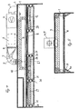
- a pressure chamber 2 is formed, to which a pipe bend 3 is connected, which is connected outside the spray booth 1 with an additional blower 4, which receives a filter 5 and at the discharge end has an elastic terminal 6, of which a Pipe bend 7 is inserted through the cabin ceiling in the pressure chamber 2.
- the insertion tube opens into a supply air duct 8, emanating from the channel branches 9, which are guided via ducts 10, 10 'as connections in the distributor supply air duct.
- the channel branches 9 with the channel baffles 10, 10 'and the terminals 12 lead the supply air into different zones 13, 14, 15, 16 which receive the lamp tubes and which are separated by the partitions and lamp holders 18, 19.
- the space into which the distributor supply air channel opens is formed by the lamp boxes 25, and is designed as a pressure channel 23. This space receives the air nozzles 20, 21, 22, which deliver the air jets 26 directed into the painting room.
- FIGS. 4 to 6 illustrated embodiment corresponds in parts of the illustration according to the Figures 1 - 3 ,
- the essential difference between the two embodiments is that the storage space between the lamp chamber and the outer wall consists of channel strands 27, 28, 29.
- the nozzles 30, 31 are each connected to the channel strand individually.
- the air flow exiting the nozzles is directed toward the interior of the cabin (against the object to be dried).
- the embodiment of the additional device according to the FIGS. 7, 8, 9 is different from the one after the FIGS. 1, 2 . 3 or 4, 5 . 6 essentially in that the supply air ducts are provided to the nozzles outside the pressure chamber, in particular over the ceiling.
Landscapes
- Engineering & Computer Science (AREA)
- Mechanical Engineering (AREA)
- General Engineering & Computer Science (AREA)
- Coating Apparatus (AREA)
- Details Or Accessories Of Spraying Plant Or Apparatus (AREA)
- Drying Of Solid Materials (AREA)
- Nozzles (AREA)
Claims (8)
- Equipement supplémentaire pour appareils de peinture et de séchage et pour équipements de séchage de la peinture de voitures et d'équipements automobiles, spécialement pour le séchage de la peinture à base d'eau, avec une enveloppe cabine fermée (1), un couvercle filtrant, au travers duquel l'air est éventuellement dirigé vers le véhicule et aspiré au niveau du sol,
où un espace pressurisé (2) est créé entre le sommet de la cabine et le filtre, d'où l'air est extrait au moyen de ventilateurs additionnels (4) placés à l'extérieur de la cabine avec un système filtrant (5) et transmis à un système de canaux (8, 9, 10), où un système de canaux d'alimentation en air est prévu, entre le dessus de la cabine et le haut du filtre ou bien au dessus de la cabine, au travers duquel l'air est envoyé puis redistribué,
où les canaux coudés d'alimentation en air (8, 9) sont placés sur le côté sous le haut du filtre et au travers desquels l'air distribué est administré au système de canaux d'alimentation grâce au ventilateur d'alimentation en air (4) équipé d'un appareil filtrant (5),
où les canaux coudés d'alimentation en air (8, 9) sont connectés aux buses de soufflage (30, 31) placées dans les emplacements des murs latéraux et au travers desquelles l'alimentation en air chauffé est dirigée inclinée vers le bas et l'intérieur en direction du véhicule,
où les canaux coudés d'alimentation en air sont connectées ou subdivisés en zones individuelles en série latéralement au haut du filtre,
caractérisée en ce que
le flot d'alimentation en air dirigé vers les buses de soufflage (30, 31) au travers du système de canaux d'alimentation (8, 9, 27, 28, 29) et placés entre les lampes d'éclairage et dirigés en direction de l'objet à sécher. - Equipement additionnel selon la revendication 1, caractérisée en ce que des canaux d'alimentation en air subdivisés en zones ou champs étant capables d'être connectés au système de distribution d'air coudé, individuellement, en groupe ou dans son ensemble.
- Equipement additionnel selon les revendications 1 ou 2, caractérisée en ce que l'absorption d'une partie de flot d'air par un ventilateur additionnel équipé de filtres dans l'espace pressurisé.
- Equipement additionnel selon les revendications 1 à 3, caractérisée en ce que le flot de distribution d'air étant dirigé au travers de canaux pressurisés entièrement hermétiques au-dessus du système d'approvisionnement en air coudé et étant dirigé sur le véhicule au travers de buses à la sortie du conduit pressurisé.
- Equipement additionnel selon les revendications 1 ou 4, caractérisée en ce que les buses étant montées individuellement ou en groupes, ajustées de telle manière que l'angle du flux d'air émis soit adaptable à l'objet ou à la pièce automobile à sécher.
- Equipement additionnel selon les revendications 1 à 5, caractérisée en ce que des vannes de balance ou bien des soupapes à air prévues dans les partitions d'alimentation en air afin de pouvoir désactiver les zones.
- Equipement additionnel selon les revendications 1 à 6, caractérisée en ce que la vitesse d'émission du flot partiel d'alimentation d'air étant indéfiniment variable.
- Equipement additionnel selon les revendications 1 à 7, caractérisée en ce que le flot d'alimentation en air au travers du système de canaux coudés d'alimentation en air étant placés entre les charnières d'éclairage et le bord du haut du filtre et étant dirigé en direction de l'objet à sécher.
Applications Claiming Priority (2)
| Application Number | Priority Date | Filing Date | Title |
|---|---|---|---|
| DE20214439U | 2002-09-17 | ||
| DE20214439U DE20214439U1 (de) | 2002-09-17 | 2002-09-17 | Zusatzvorrichtung für Farbspritzanlagen |
Publications (3)
| Publication Number | Publication Date |
|---|---|
| EP1400285A2 EP1400285A2 (fr) | 2004-03-24 |
| EP1400285A3 EP1400285A3 (fr) | 2004-05-12 |
| EP1400285B1 true EP1400285B1 (fr) | 2008-03-26 |
Family
ID=7975206
Family Applications (1)
| Application Number | Title | Priority Date | Filing Date |
|---|---|---|---|
| EP02023176A Expired - Lifetime EP1400285B1 (fr) | 2002-09-17 | 2002-10-16 | Dispositif auxiliaire pour une installation de peinture au pistolet |
Country Status (3)
| Country | Link |
|---|---|
| EP (1) | EP1400285B1 (fr) |
| AT (1) | ATE390211T1 (fr) |
| DE (3) | DE20214439U1 (fr) |
Cited By (1)
| Publication number | Priority date | Publication date | Assignee | Title |
|---|---|---|---|---|
| CN111992407A (zh) * | 2020-09-01 | 2020-11-27 | 兴三星云科技有限公司 | 超长立体式锌铝合金铸件喷塑涂装流水线及其加工方法 |
Families Citing this family (7)
| Publication number | Priority date | Publication date | Assignee | Title |
|---|---|---|---|---|
| ATE456015T1 (de) | 2007-03-06 | 2010-02-15 | Alfa Dis | Trocknungsvorrichtung und verfahren für bemalte körper, und vorrichtung zur zirkulation von trocknungsluft in einer solchen vorrichtung und bei einem solchen verfahren |
| CN106827154B (zh) * | 2016-12-20 | 2019-01-22 | 重庆坤秀门窗有限公司 | 一种套装门的制作工艺 |
| CN109675752B (zh) * | 2019-01-26 | 2021-01-12 | 江西中超泵业有限公司 | 一种离心泵泵壳加工用喷涂装置 |
| CN112013665A (zh) * | 2020-08-18 | 2020-12-01 | 涌明科技(上海)有限公司 | 一种半导体芯片除湿及抗氧化装置 |
| CN113996476B (zh) * | 2021-10-26 | 2023-04-07 | 广东奥迪威传感科技股份有限公司 | 滴灌喷涂生产线 |
| CN117019497B (zh) * | 2023-10-07 | 2023-12-22 | 江苏鑫弘汽车零部件制造有限公司 | 一种刹车片喷涂装置 |
| CN118268095B (zh) * | 2024-05-09 | 2025-12-30 | 浙江泰通医化设备股份有限公司 | 一种回转真空粉碎干燥机 |
Family Cites Families (4)
| Publication number | Priority date | Publication date | Assignee | Title |
|---|---|---|---|---|
| DE69301001T3 (de) * | 1992-04-30 | 1999-04-15 | Imperial Chemical Industries Plc, London | Lackierkabine und Verfahren zur Beschleunigung der Verdampfung des Verdünners aus einer Beschichtung auf einer Plattenoberfläche |
| US5456023A (en) * | 1994-06-28 | 1995-10-10 | Ransburg Corporation | Advance cure paint spray booth |
| BE1009345A3 (nl) * | 1995-04-19 | 1997-02-04 | Belmeko Engineering Nv | Behandelingswijze en- inrichting met gedwongen luchtcirculatie. |
| GB9702473D0 (en) * | 1997-02-07 | 1997-03-26 | Junair Spraybooths Ltd | Spraybooth |
-
2002
- 2002-09-17 DE DE20214439U patent/DE20214439U1/de not_active Expired - Lifetime
- 2002-10-16 AT AT02023176T patent/ATE390211T1/de active
- 2002-10-16 DE DE50211970T patent/DE50211970D1/de not_active Expired - Lifetime
- 2002-10-16 DE DE20221848U patent/DE20221848U1/de not_active Expired - Lifetime
- 2002-10-16 EP EP02023176A patent/EP1400285B1/fr not_active Expired - Lifetime
Cited By (2)
| Publication number | Priority date | Publication date | Assignee | Title |
|---|---|---|---|---|
| CN111992407A (zh) * | 2020-09-01 | 2020-11-27 | 兴三星云科技有限公司 | 超长立体式锌铝合金铸件喷塑涂装流水线及其加工方法 |
| CN111992407B (zh) * | 2020-09-01 | 2021-08-17 | 兴三星云科技有限公司 | 超长立体式锌铝合金铸件喷塑涂装流水线及其加工方法 |
Also Published As
| Publication number | Publication date |
|---|---|
| ATE390211T1 (de) | 2008-04-15 |
| DE20221848U1 (de) | 2008-06-26 |
| DE50211970D1 (de) | 2008-05-08 |
| EP1400285A2 (fr) | 2004-03-24 |
| EP1400285A3 (fr) | 2004-05-12 |
| DE20214439U1 (de) | 2002-12-19 |
Similar Documents
| Publication | Publication Date | Title |
|---|---|---|
| DE69817157T2 (de) | Trocknungsvorrichtung in einer spritzkabine | |
| DE2844118C2 (de) | Überzugauftragskabine | |
| DE1427595C3 (de) | Farbspritzkanal für die Spritzbehandlung von durch ihn hindurch bewegbaren Gegenständen | |
| DE2540983C2 (de) | Oberflächenbehandlungsanlage und Verfahren zur Belüftung derselben | |
| DE1427597B2 (de) | Farbspritzkanal fuer die spritzbehandlung von durch ihn hindurchbewegbaren gegenstaenden | |
| WO2012016637A1 (fr) | Dispositif de traitement de surface d'objets | |
| EP1400285B1 (fr) | Dispositif auxiliaire pour une installation de peinture au pistolet | |
| EP0777534B1 (fr) | Dispositif de mise en peinture de pieces par pulverisation | |
| DE19937193B4 (de) | Verfahren zum Trocknen von wasserhaltigem Basislack sowie Einrichtung und Nachrüstsatz für Lackierkabinen zur Durchführung des Verfahrens | |
| DE102008013714A1 (de) | Vorrichtung und Verfahren zum Zuführen von Luft zu einem Applikationsbereich einer Lackieranlage | |
| EP2244839B2 (fr) | Installation de peinture | |
| DE102016013589A1 (de) | Trockenraum | |
| DE102013000754A1 (de) | Vorrichtung zum Temperieren von Gegenständen | |
| DE19527415A1 (de) | Verfahren und Vorrichtung zum Trocknen von keramischen Formlingen | |
| DE2851046A1 (de) | Luftauslassvorrichtung fuer raumklimatisierungs- und belueftungsanlagen | |
| DE19746415C1 (de) | Kühlzone einer Lackieranlage und Verfahren zur Minimierung der Bildung von Lacklösemittelkondensat im Deckenbereich dieser Kühlzone | |
| DE102011122056A1 (de) | Anlage zum Beschichten von Gegenständen | |
| DE2303430C3 (de) | Vorrichtung zum Reinigen von gasförmigen Stoffen, welche Farbstoff, Lack bzw. Zellulose enthalten | |
| DE19736799C1 (de) | Luftauslaßvorrichtung für Lüftungs- und Klimaanlagen | |
| DE202004014233U1 (de) | Belüftungsvorrichtung für Lackier- und/oder Trocknungsanlagen sowie eine solche Lackier- und/oder Trocknungsanlage | |
| DE1646206B2 (de) | Vorrichtung zum ueberziehen von gegenstaenden mit thermoplastischem material | |
| WO2019025377A1 (fr) | Ensemble ventilateur | |
| EP4294683B1 (fr) | Dispositif pour l'élimination sans contact de gouttes d'eau restant sur des surfaces extérieures de véhicule après un lavage de véhicule | |
| DE102019213430A1 (de) | Trennvorrichtung, Behandlungsanlage, Verfahren zum Trennen zweier Raumbereiche und Verfahren zum Behandeln von Werkstücken | |
| DE102008019231A1 (de) | Lackiervorrichtung |
Legal Events
| Date | Code | Title | Description |
|---|---|---|---|
| PUAI | Public reference made under article 153(3) epc to a published international application that has entered the european phase |
Free format text: ORIGINAL CODE: 0009012 |
|
| AK | Designated contracting states |
Kind code of ref document: A2 Designated state(s): AT BE BG CH CY CZ DE DK EE ES FI FR GB GR IE IT LI LU MC NL PT SE SK TR |
|
| AX | Request for extension of the european patent |
Extension state: AL LT LV MK RO SI |
|
| PUAL | Search report despatched |
Free format text: ORIGINAL CODE: 0009013 |
|
| AK | Designated contracting states |
Kind code of ref document: A3 Designated state(s): AT BE BG CH CY CZ DE DK EE ES FI FR GB GR IE IT LI LU MC NL PT SE SK TR |
|
| AX | Request for extension of the european patent |
Extension state: AL LT LV MK RO SI |
|
| 17P | Request for examination filed |
Effective date: 20041109 |
|
| AKX | Designation fees paid |
Designated state(s): AT BE BG CH CY CZ DE DK EE ES FI FR GB GR IE IT LI LU MC NL PT SE SK TR |
|
| RAP1 | Party data changed (applicant data changed or rights of an application transferred) |
Owner name: WOLF VERWALTUNGS GMBH & CO. KG |
|
| 17Q | First examination report despatched |
Effective date: 20070427 |
|
| GRAP | Despatch of communication of intention to grant a patent |
Free format text: ORIGINAL CODE: EPIDOSNIGR1 |
|
| GRAS | Grant fee paid |
Free format text: ORIGINAL CODE: EPIDOSNIGR3 |
|
| GRAA | (expected) grant |
Free format text: ORIGINAL CODE: 0009210 |
|
| AK | Designated contracting states |
Kind code of ref document: B1 Designated state(s): AT BE BG CH CY CZ DE DK EE ES FI FR GB GR IE IT LI LU MC NL PT SE SK TR |
|
| REG | Reference to a national code |
Ref country code: GB Ref legal event code: FG4D Free format text: NOT ENGLISH |
|
| REG | Reference to a national code |
Ref country code: IE Ref legal event code: FG4D Free format text: LANGUAGE OF EP DOCUMENT: GERMAN Ref country code: CH Ref legal event code: EP |
|
| REF | Corresponds to: |
Ref document number: 50211970 Country of ref document: DE Date of ref document: 20080508 Kind code of ref document: P |
|
| PG25 | Lapsed in a contracting state [announced via postgrant information from national office to epo] |
Ref country code: FI Free format text: LAPSE BECAUSE OF FAILURE TO SUBMIT A TRANSLATION OF THE DESCRIPTION OR TO PAY THE FEE WITHIN THE PRESCRIBED TIME-LIMIT Effective date: 20080326 |
|
| REG | Reference to a national code |
Ref country code: CH Ref legal event code: NV Representative=s name: MEYER & KOLLEGEN |
|
| NLV1 | Nl: lapsed or annulled due to failure to fulfill the requirements of art. 29p and 29m of the patents act | ||
| REG | Reference to a national code |
Ref country code: IE Ref legal event code: FD4D |
|
| PG25 | Lapsed in a contracting state [announced via postgrant information from national office to epo] |
Ref country code: PT Free format text: LAPSE BECAUSE OF FAILURE TO SUBMIT A TRANSLATION OF THE DESCRIPTION OR TO PAY THE FEE WITHIN THE PRESCRIBED TIME-LIMIT Effective date: 20080901 Ref country code: SE Free format text: LAPSE BECAUSE OF FAILURE TO SUBMIT A TRANSLATION OF THE DESCRIPTION OR TO PAY THE FEE WITHIN THE PRESCRIBED TIME-LIMIT Effective date: 20080626 Ref country code: SK Free format text: LAPSE BECAUSE OF FAILURE TO SUBMIT A TRANSLATION OF THE DESCRIPTION OR TO PAY THE FEE WITHIN THE PRESCRIBED TIME-LIMIT Effective date: 20080326 Ref country code: ES Free format text: LAPSE BECAUSE OF FAILURE TO SUBMIT A TRANSLATION OF THE DESCRIPTION OR TO PAY THE FEE WITHIN THE PRESCRIBED TIME-LIMIT Effective date: 20080707 Ref country code: CZ Free format text: LAPSE BECAUSE OF FAILURE TO SUBMIT A TRANSLATION OF THE DESCRIPTION OR TO PAY THE FEE WITHIN THE PRESCRIBED TIME-LIMIT Effective date: 20080326 |
|
| PG25 | Lapsed in a contracting state [announced via postgrant information from national office to epo] |
Ref country code: NL Free format text: LAPSE BECAUSE OF FAILURE TO SUBMIT A TRANSLATION OF THE DESCRIPTION OR TO PAY THE FEE WITHIN THE PRESCRIBED TIME-LIMIT Effective date: 20080326 |
|
| EN | Fr: translation not filed | ||
| PG25 | Lapsed in a contracting state [announced via postgrant information from national office to epo] |
Ref country code: IE Free format text: LAPSE BECAUSE OF FAILURE TO SUBMIT A TRANSLATION OF THE DESCRIPTION OR TO PAY THE FEE WITHIN THE PRESCRIBED TIME-LIMIT Effective date: 20080326 Ref country code: DK Free format text: LAPSE BECAUSE OF FAILURE TO SUBMIT A TRANSLATION OF THE DESCRIPTION OR TO PAY THE FEE WITHIN THE PRESCRIBED TIME-LIMIT Effective date: 20080326 |
|
| PLBE | No opposition filed within time limit |
Free format text: ORIGINAL CODE: 0009261 |
|
| STAA | Information on the status of an ep patent application or granted ep patent |
Free format text: STATUS: NO OPPOSITION FILED WITHIN TIME LIMIT |
|
| 26N | No opposition filed |
Effective date: 20081230 |
|
| BERE | Be: lapsed |
Owner name: WOLF VERWALTUNGS G.M.B.H. & CO. KG Effective date: 20081031 |
|
| PG25 | Lapsed in a contracting state [announced via postgrant information from national office to epo] |
Ref country code: FR Free format text: LAPSE BECAUSE OF FAILURE TO SUBMIT A TRANSLATION OF THE DESCRIPTION OR TO PAY THE FEE WITHIN THE PRESCRIBED TIME-LIMIT Effective date: 20090116 Ref country code: BG Free format text: LAPSE BECAUSE OF FAILURE TO SUBMIT A TRANSLATION OF THE DESCRIPTION OR TO PAY THE FEE WITHIN THE PRESCRIBED TIME-LIMIT Effective date: 20080626 Ref country code: EE Free format text: LAPSE BECAUSE OF FAILURE TO SUBMIT A TRANSLATION OF THE DESCRIPTION OR TO PAY THE FEE WITHIN THE PRESCRIBED TIME-LIMIT Effective date: 20080326 |
|
| PG25 | Lapsed in a contracting state [announced via postgrant information from national office to epo] |
Ref country code: MC Free format text: LAPSE BECAUSE OF NON-PAYMENT OF DUE FEES Effective date: 20081031 |
|
| REG | Reference to a national code |
Ref country code: CH Ref legal event code: PL |
|
| GBPC | Gb: european patent ceased through non-payment of renewal fee |
Effective date: 20081016 |
|
| PG25 | Lapsed in a contracting state [announced via postgrant information from national office to epo] |
Ref country code: IT Free format text: LAPSE BECAUSE OF FAILURE TO SUBMIT A TRANSLATION OF THE DESCRIPTION OR TO PAY THE FEE WITHIN THE PRESCRIBED TIME-LIMIT Effective date: 20080326 |
|
| PG25 | Lapsed in a contracting state [announced via postgrant information from national office to epo] |
Ref country code: BE Free format text: LAPSE BECAUSE OF NON-PAYMENT OF DUE FEES Effective date: 20081031 Ref country code: CY Free format text: LAPSE BECAUSE OF FAILURE TO SUBMIT A TRANSLATION OF THE DESCRIPTION OR TO PAY THE FEE WITHIN THE PRESCRIBED TIME-LIMIT Effective date: 20080326 |
|
| PG25 | Lapsed in a contracting state [announced via postgrant information from national office to epo] |
Ref country code: LI Free format text: LAPSE BECAUSE OF NON-PAYMENT OF DUE FEES Effective date: 20081031 Ref country code: CH Free format text: LAPSE BECAUSE OF NON-PAYMENT OF DUE FEES Effective date: 20081031 |
|
| PG25 | Lapsed in a contracting state [announced via postgrant information from national office to epo] |
Ref country code: GB Free format text: LAPSE BECAUSE OF NON-PAYMENT OF DUE FEES Effective date: 20081016 |
|
| PG25 | Lapsed in a contracting state [announced via postgrant information from national office to epo] |
Ref country code: LU Free format text: LAPSE BECAUSE OF NON-PAYMENT OF DUE FEES Effective date: 20081016 |
|
| PG25 | Lapsed in a contracting state [announced via postgrant information from national office to epo] |
Ref country code: TR Free format text: LAPSE BECAUSE OF FAILURE TO SUBMIT A TRANSLATION OF THE DESCRIPTION OR TO PAY THE FEE WITHIN THE PRESCRIBED TIME-LIMIT Effective date: 20080326 |
|
| PG25 | Lapsed in a contracting state [announced via postgrant information from national office to epo] |
Ref country code: GR Free format text: LAPSE BECAUSE OF FAILURE TO SUBMIT A TRANSLATION OF THE DESCRIPTION OR TO PAY THE FEE WITHIN THE PRESCRIBED TIME-LIMIT Effective date: 20080627 |
|
| REG | Reference to a national code |
Ref country code: DE Ref legal event code: R082 Ref document number: 50211970 Country of ref document: DE Representative=s name: PATENTANWALTSKANZLEI MEYER, DE |
|
| REG | Reference to a national code |
Ref country code: DE Ref legal event code: R082 Ref document number: 50211970 Country of ref document: DE Representative=s name: PATENTANWALTSKANZLEI MEYER, DE Effective date: 20140630 Ref country code: DE Ref legal event code: R081 Ref document number: 50211970 Country of ref document: DE Owner name: WOLF ANLAGEN-TECHNIK GMBH & CO. KG, DE Free format text: FORMER OWNER: WOLF VERWALTUNGS GMBH & CO. KG, 85290 GEISENFELD, DE Effective date: 20140630 |
|
| REG | Reference to a national code |
Ref country code: AT Ref legal event code: PC Ref document number: 390211 Country of ref document: AT Kind code of ref document: T Owner name: WOLF ANLAGEN-TECHNIK GMBH & CO.KG, DE Effective date: 20141215 |
|
| REG | Reference to a national code |
Ref country code: DE Ref legal event code: R079 Ref document number: 50211970 Country of ref document: DE Free format text: PREVIOUS MAIN CLASS: B05B0015120000 Ipc: B05B0016000000 |
|
| PGFP | Annual fee paid to national office [announced via postgrant information from national office to epo] |
Ref country code: AT Payment date: 20211019 Year of fee payment: 20 Ref country code: DE Payment date: 20210830 Year of fee payment: 20 |
|
| REG | Reference to a national code |
Ref country code: DE Ref legal event code: R071 Ref document number: 50211970 Country of ref document: DE |
|
| REG | Reference to a national code |
Ref country code: AT Ref legal event code: MK07 Ref document number: 390211 Country of ref document: AT Kind code of ref document: T Effective date: 20221016 |
|
| P01 | Opt-out of the competence of the unified patent court (upc) registered |
Effective date: 20230523 |