EP1400298A2 - Agencement d'une scie à onglet avec une capacité de coupe augmentée - Google Patents
Agencement d'une scie à onglet avec une capacité de coupe augmentée Download PDFInfo
- Publication number
- EP1400298A2 EP1400298A2 EP03020390A EP03020390A EP1400298A2 EP 1400298 A2 EP1400298 A2 EP 1400298A2 EP 03020390 A EP03020390 A EP 03020390A EP 03020390 A EP03020390 A EP 03020390A EP 1400298 A2 EP1400298 A2 EP 1400298A2
- Authority
- EP
- European Patent Office
- Prior art keywords
- axis
- housing
- miter saw
- saw
- upper blade
- Prior art date
- Legal status (The legal status is an assumption and is not a legal conclusion. Google has not performed a legal analysis and makes no representation as to the accuracy of the status listed.)
- Withdrawn
Links
Images

Classifications
-
- B—PERFORMING OPERATIONS; TRANSPORTING
- B23—MACHINE TOOLS; METAL-WORKING NOT OTHERWISE PROVIDED FOR
- B23D—PLANING; SLOTTING; SHEARING; BROACHING; SAWING; FILING; SCRAPING; LIKE OPERATIONS FOR WORKING METAL BY REMOVING MATERIAL, NOT OTHERWISE PROVIDED FOR
- B23D45/00—Sawing machines or sawing devices with circular saw blades or with friction saw discs
- B23D45/04—Sawing machines or sawing devices with circular saw blades or with friction saw discs with a circular saw blade or the stock carried by a pivoted lever
- B23D45/042—Sawing machines or sawing devices with circular saw blades or with friction saw discs with a circular saw blade or the stock carried by a pivoted lever with the saw blade carried by a pivoted lever
- B23D45/044—Sawing machines or sawing devices with circular saw blades or with friction saw discs with a circular saw blade or the stock carried by a pivoted lever with the saw blade carried by a pivoted lever the saw blade being adjustable according to angle of cut
-
- B—PERFORMING OPERATIONS; TRANSPORTING
- B23—MACHINE TOOLS; METAL-WORKING NOT OTHERWISE PROVIDED FOR
- B23D—PLANING; SLOTTING; SHEARING; BROACHING; SAWING; FILING; SCRAPING; LIKE OPERATIONS FOR WORKING METAL BY REMOVING MATERIAL, NOT OTHERWISE PROVIDED FOR
- B23D45/00—Sawing machines or sawing devices with circular saw blades or with friction saw discs
- B23D45/02—Sawing machines or sawing devices with circular saw blades or with friction saw discs with a circular saw blade or the stock mounted on a carriage
- B23D45/021—Sawing machines or sawing devices with circular saw blades or with friction saw discs with a circular saw blade or the stock mounted on a carriage with the saw blade mounted on a carriage
- B23D45/024—Sawing machines or sawing devices with circular saw blades or with friction saw discs with a circular saw blade or the stock mounted on a carriage with the saw blade mounted on a carriage the saw blade being adjustable according to depth or angle of cut
-
- B—PERFORMING OPERATIONS; TRANSPORTING
- B23—MACHINE TOOLS; METAL-WORKING NOT OTHERWISE PROVIDED FOR
- B23D—PLANING; SLOTTING; SHEARING; BROACHING; SAWING; FILING; SCRAPING; LIKE OPERATIONS FOR WORKING METAL BY REMOVING MATERIAL, NOT OTHERWISE PROVIDED FOR
- B23D47/00—Sawing machines or sawing devices working with circular saw blades, characterised only by constructional features of particular parts
-
- Y—GENERAL TAGGING OF NEW TECHNOLOGICAL DEVELOPMENTS; GENERAL TAGGING OF CROSS-SECTIONAL TECHNOLOGIES SPANNING OVER SEVERAL SECTIONS OF THE IPC; TECHNICAL SUBJECTS COVERED BY FORMER USPC CROSS-REFERENCE ART COLLECTIONS [XRACs] AND DIGESTS
- Y10—TECHNICAL SUBJECTS COVERED BY FORMER USPC
- Y10T—TECHNICAL SUBJECTS COVERED BY FORMER US CLASSIFICATION
- Y10T409/00—Gear cutting, milling, or planing
- Y10T409/10—Gear cutting
- Y10T409/101431—Gear tooth shape generating
- Y10T409/10477—Gear tooth shape generating by relative axial movement between synchronously indexing or rotating work and cutter
-
- Y—GENERAL TAGGING OF NEW TECHNOLOGICAL DEVELOPMENTS; GENERAL TAGGING OF CROSS-SECTIONAL TECHNOLOGIES SPANNING OVER SEVERAL SECTIONS OF THE IPC; TECHNICAL SUBJECTS COVERED BY FORMER USPC CROSS-REFERENCE ART COLLECTIONS [XRACs] AND DIGESTS
- Y10—TECHNICAL SUBJECTS COVERED BY FORMER USPC
- Y10T—TECHNICAL SUBJECTS COVERED BY FORMER US CLASSIFICATION
- Y10T83/00—Cutting
- Y10T83/869—Means to drive or to guide tool
- Y10T83/8773—Bevel or miter cut
Definitions
- This invention relates generally to miter saws and specifically to arrangements for increasing cutting capacity in slide and/or non-sliding miter saws.
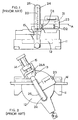
- non-sliding and slide miter saws both have a base 11, a rotatable table 12 attached to the base 11, a saw assembly 20 including a motor 21, a blade 22 rotatable about axis A and driven by the motor 21, a cover housing 23 covering motor 21, an upper blade guard 24 covering the upper part of blade 22, and a lower guard 25 (shown in broken lines) pivotably attached to upper blade guard 24 for covering the lower part of blade 21. Accordingly, the saw assembly 20 is pivoted downwardly for cutting a workpiece disposed on the base 11 and table 12.
- slide miter saws enable the user to move the saw assembly horizontally along the table. As shown in FIG. 2, most slide miter saws accomplish this by connecting the upper blade guard 24 (and thus the saw assembly 20) to a pivot arm, which in turn is connected to a trunnion 13, which is fixedly connected to at least one rail 14, which is slidably attached to a support housing 15 connected to the table 12 (see, e.g., US Patent No. 6,067,885). With such arrangement, the user would pull the saw assembly 20 forwardly, move the saw assembly 20 downwardly, then push the saw assembly 20 rearwardly for cutting the workpiece W.
- an improved miter saw is employed.
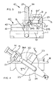
- the miter saw includes a base, a table rotatably attached to the base, a saw assembly connected to the table, the saw assembly comprising a motor, a blade rotatable about an axis and driven by the motor, an upper blade guard for covering an upper part of the blade and having a bottom surface, and a housing connected to the upper blade guard, the housing having a bottom surface disposed below the axis, wherein a first distance between the axis and the bottom surface of at least one of the housing and the upper blade guard at a first point along the axis near the upper blade guard is smaller than a second distance between the axis and the bottom surface of at least one of the housing and the upper blade guard at a second point along the axis, the second point being farther away from the upper blade guard than the first point.
- a slide miter saw 10 preferably has a base 11, a table 12 rotatably connected to the base 11, a support housing 15 pivotally connected to table 12, at least one (and preferably two) rail(s) 14 slidably connected to the support housing 15, a trunnion 13 attached to one end of the rail(s) 15, and a saw assembly 20 which comprises a pivot arm 26A pivotably attached to trunnion 13, a motor 21, a blade 22 rotatable about axis A and driven by the motor 21, an upper blade guard 24 for covering an upper part of blade 22, and a lower blade 25 pivotally attached to the upper blade guard 24 for covering a lower part of blade 22.
- the motor 21 is attached to the upper blade guard 17.
- the slide miter saw 10 may also have a movable fence assembly 40 attached to the base 11.
- Movable fence assembly 40 preferably extends laterally across table 12, against which a workpiece can be positioned and supported for performing a cutting operation thereon.
- Movable fence assembly 40 may include a fixed fence 41 attached to base 11, and a movable fence 42 connected to the fixed fence 41.
- movable fence 42 is slidably attached to fixed fence 41.
- Motor 21 may be covered by a cover housing 23 attached to the upper blade guard 24.
- Cover housing 23 may cover motor 21 and/or any transmissions disposed between the motor 21 and blade 22.
- Cover housing 23 may have a lower or bottom surface 23S, which is preferably below the axis A.
- upper blade guard 24 may have a lower or bottom surface 24S, which may be below axis A.
- blade 22 is mounted on a spindle 16, which extends into cover housing 23, and is driven by motor 21.
- Spindle 16 may be supported by bearings 17, 18.
- Blade 22 may be clamped unto spindle 16 via clamps 26, 27 disposed on both sides of blade 22, and held in place by a bolt 28, which is preferably threaded into spindle 16.
- a pocket 30 may be created by manipulating the distances between axis A and bottom surfaces 23S and/or 24S.
- point Y is farther away from the upper blade guard 24 than point X.
- points X and Y are disposed along axis A on the same side of blade 22.
- pocket 30 is created.
- the height and width of pocket 30 is about 3.33 inches and about 1.744 inches, respectively, for a miter saw that carries a blade with a diameter of about 8.5 inches.
- a user could cut a 3 1 ⁇ 4" base molding placed vertically against fence assembly 40 at a miter angle of about 42° to about 48°. Such cut is achieved when the saw assembly 20 is placed near the fence and moved downwardly in a chopping action, rather than sliding it across the workpiece.
- pocket 30 can be modified according to design requirements and specifications, etc.
Landscapes
- Engineering & Computer Science (AREA)
- Mechanical Engineering (AREA)
- Sawing (AREA)
Priority Applications (1)
| Application Number | Priority Date | Filing Date | Title |
|---|---|---|---|
| EP20050023455 EP1621276B1 (fr) | 2002-09-17 | 2003-09-10 | Agencement d'une scie à onglet avec une capacité de coupe augmentée |
Applications Claiming Priority (2)
| Application Number | Priority Date | Filing Date | Title |
|---|---|---|---|
| US245439 | 1994-05-18 | ||
| US10/245,439 US20040052599A1 (en) | 2002-09-17 | 2002-09-17 | Miter saw arrangement for increased cutting capacity |
Related Child Applications (1)
| Application Number | Title | Priority Date | Filing Date |
|---|---|---|---|
| EP20050023455 Division EP1621276B1 (fr) | 2002-09-17 | 2003-09-10 | Agencement d'une scie à onglet avec une capacité de coupe augmentée |
Publications (2)
| Publication Number | Publication Date |
|---|---|
| EP1400298A2 true EP1400298A2 (fr) | 2004-03-24 |
| EP1400298A3 EP1400298A3 (fr) | 2004-08-11 |
Family
ID=28791703
Family Applications (2)
| Application Number | Title | Priority Date | Filing Date |
|---|---|---|---|
| EP20050023455 Expired - Lifetime EP1621276B1 (fr) | 2002-09-17 | 2003-09-10 | Agencement d'une scie à onglet avec une capacité de coupe augmentée |
| EP20030020390 Withdrawn EP1400298A3 (fr) | 2002-09-17 | 2003-09-10 | Agencement d'une scie à onglet avec une capacité de coupe augmentée |
Family Applications Before (1)
| Application Number | Title | Priority Date | Filing Date |
|---|---|---|---|
| EP20050023455 Expired - Lifetime EP1621276B1 (fr) | 2002-09-17 | 2003-09-10 | Agencement d'une scie à onglet avec une capacité de coupe augmentée |
Country Status (5)
| Country | Link |
|---|---|
| US (1) | US20040052599A1 (fr) |
| EP (2) | EP1621276B1 (fr) |
| CN (1) | CN1500584A (fr) |
| SE (1) | SE527312C2 (fr) |
| TW (1) | TW200406291A (fr) |
Families Citing this family (3)
| Publication number | Priority date | Publication date | Assignee | Title |
|---|---|---|---|---|
| JP4552759B2 (ja) * | 2005-05-27 | 2010-09-29 | 日立工機株式会社 | 卓上切断機 |
| GB2443639B (en) * | 2006-11-09 | 2010-08-25 | Ian Briggs | Wet weather cover for a sliding compound mitre saw |
| JP5429524B2 (ja) * | 2008-03-11 | 2014-02-26 | 日立工機株式会社 | 卓上切断機 |
Family Cites Families (15)
| Publication number | Priority date | Publication date | Assignee | Title |
|---|---|---|---|---|
| US3565136A (en) * | 1969-04-21 | 1971-02-23 | Black & Decker Mfg Co | Depth of cut adjustment construction for a radial-arm saw |
| US4152961A (en) * | 1978-01-18 | 1979-05-08 | The Singer Company | Radial saw |
| US4694721A (en) * | 1986-04-08 | 1987-09-22 | Delta International Machinery Corp. | Motor pack for circular saw |
| US4817581A (en) * | 1988-02-10 | 1989-04-04 | Federal-Mogul Corporation | Adjustable support for cutting apparatus |
| JP2573057B2 (ja) | 1989-07-07 | 1997-01-16 | 株式会社マキタ | 卓上丸鋸盤 |
| US5285708A (en) * | 1992-05-18 | 1994-02-15 | Porter-Cable Corporation | Miter saw alignment system |
| DE69313011T2 (de) * | 1992-05-22 | 1998-03-19 | Makita Corp | Gehrungssäge |
| US5265511A (en) * | 1992-08-13 | 1993-11-30 | Milwaukee Electric Tool Corporation | Controlled axial position hinge assembly |
| US5249496A (en) * | 1992-08-13 | 1993-10-05 | Milwaukee Electric Tool Corporation | Indexing detent override mechanism |
| CA2096786A1 (fr) * | 1992-08-13 | 1994-02-14 | Andrew Lubomir Itzov | Scie a moteur munie d'une tringlerie de commande du protecteur de lame amovible |
| US5404779A (en) * | 1993-06-09 | 1995-04-11 | Tapco Products Company, Inc. | Saw table with compound movement of saw |
| GB9314164D0 (en) * | 1993-07-08 | 1993-08-18 | Black & Decker Inc | Chop saw arrangement |
| US5755148A (en) * | 1995-07-07 | 1998-05-26 | Black & Decker Inc. | Adjustable fence for a compound miter saw |
| US5802943A (en) * | 1996-12-05 | 1998-09-08 | Black & Decker Inc. | Bevel locking system for a sliding compound miter saw |
| TW496222U (en) | 2001-07-20 | 2002-07-21 | Lee Yeong Ind Co Ltd | Circular saw with horizontal stretch guiding for sawing |
-
2002
- 2002-09-17 US US10/245,439 patent/US20040052599A1/en not_active Abandoned
-
2003
- 2003-09-05 SE SE0302384A patent/SE527312C2/sv not_active IP Right Cessation
- 2003-09-08 TW TW92124740A patent/TW200406291A/zh unknown
- 2003-09-10 EP EP20050023455 patent/EP1621276B1/fr not_active Expired - Lifetime
- 2003-09-10 EP EP20030020390 patent/EP1400298A3/fr not_active Withdrawn
- 2003-09-16 CN CNA031581862A patent/CN1500584A/zh active Pending
Also Published As
| Publication number | Publication date |
|---|---|
| CN1500584A (zh) | 2004-06-02 |
| SE0302384D0 (sv) | 2003-09-05 |
| EP1400298A3 (fr) | 2004-08-11 |
| SE527312C2 (sv) | 2006-02-07 |
| SE0302384L (sv) | 2004-03-18 |
| US20040052599A1 (en) | 2004-03-18 |
| TW200406291A (en) | 2004-05-01 |
| EP1621276A1 (fr) | 2006-02-01 |
| EP1621276B1 (fr) | 2013-01-02 |
Similar Documents
| Publication | Publication Date | Title |
|---|---|---|
| US6470778B1 (en) | Dust collector for a power tool | |
| CA2064619C (fr) | Scie a onglet motorisee | |
| US7819044B2 (en) | Fence arrangement for a slide miter saw | |
| EP1614511B1 (fr) | Garde pour la lame d'une scie | |
| EP1400297A2 (fr) | Scie à onglets du type glissant | |
| EP1550525A2 (fr) | Une scie à onglet | |
| EP1398123A3 (fr) | Mécanisme de butée pour l'angle de biseau pour une scie à onglet | |
| EP1621302A1 (fr) | Dispositif de butée pour des scies à onglets | |
| EP1386685B1 (fr) | Système de protection d'une butée pour une scie à onglet coulissante | |
| US6994007B2 (en) | Chop saw | |
| EP1400298A2 (fr) | Agencement d'une scie à onglet avec une capacité de coupe augmentée | |
| EP1716987B1 (fr) | Dispositif de butée pour scie à onglet | |
| CA2302032C (fr) | Scie a onglets | |
| EP0949048B1 (fr) | Scie à onglet à butée angulairement ajustable | |
| EP1623800B1 (fr) | Dispositif de verrouillage d'une table pour des scies | |
| JP3215966B2 (ja) | スライド式卓上丸鋸盤 | |
| EP1852227B1 (fr) | Ensemble de protection de lame pour scies | |
| CA3097979A1 (en) | Miter saw | |
| JPH0857808A (ja) | 卓上丸鋸盤 | |
| EP1182000B1 (fr) | Scie à onglets | |
| EP1614512A1 (fr) | Commande de la profondeur pour une scie à table |
Legal Events
| Date | Code | Title | Description |
|---|---|---|---|
| PUAI | Public reference made under article 153(3) epc to a published international application that has entered the european phase |
Free format text: ORIGINAL CODE: 0009012 |
|
| AK | Designated contracting states |
Kind code of ref document: A2 Designated state(s): AT BE BG CH CY CZ DE DK EE ES FI FR GB GR HU IE IT LI LU MC NL PT RO SE SI SK TR |
|
| AX | Request for extension of the european patent |
Extension state: AL LT LV MK |
|
| PUAL | Search report despatched |
Free format text: ORIGINAL CODE: 0009013 |
|
| AK | Designated contracting states |
Kind code of ref document: A3 Designated state(s): AT BE BG CH CY CZ DE DK EE ES FI FR GB GR HU IE IT LI LU MC NL PT RO SE SI SK TR |
|
| AX | Request for extension of the european patent |
Extension state: AL LT LV MK |
|
| 17P | Request for examination filed |
Effective date: 20040922 |
|
| 17Q | First examination report despatched |
Effective date: 20041215 |
|
| AKX | Designation fees paid |
Designated state(s): AT BE BG CH CY CZ DE DK EE ES FI FR GB GR HU IE IT LI LU MC NL PT RO SE SI SK TR |
|
| STAA | Information on the status of an ep patent application or granted ep patent |
Free format text: STATUS: THE APPLICATION IS DEEMED TO BE WITHDRAWN |
|
| 18D | Application deemed to be withdrawn |
Effective date: 20051112 |