EP1400332A1 - Verfahren und Vorrichtung zum Dosieren eines Additives bei der Zufuhr einer Spritzgiesspresse, sowie Spritzgiesspresse mit einer Dosiervorrichtung - Google Patents
Verfahren und Vorrichtung zum Dosieren eines Additives bei der Zufuhr einer Spritzgiesspresse, sowie Spritzgiesspresse mit einer Dosiervorrichtung Download PDFInfo
- Publication number
- EP1400332A1 EP1400332A1 EP02020872A EP02020872A EP1400332A1 EP 1400332 A1 EP1400332 A1 EP 1400332A1 EP 02020872 A EP02020872 A EP 02020872A EP 02020872 A EP02020872 A EP 02020872A EP 1400332 A1 EP1400332 A1 EP 1400332A1
- Authority
- EP
- European Patent Office
- Prior art keywords
- additive
- phase
- extrusion screw
- polymer
- flow rate
- Prior art date
- Legal status (The legal status is an assumption and is not a legal conclusion. Google has not performed a legal analysis and makes no representation as to the accuracy of the status listed.)
- Granted
Links
- 239000000654 additive Substances 0.000 title claims abstract description 124
- 230000000996 additive effect Effects 0.000 title claims abstract description 121
- 238000001746 injection moulding Methods 0.000 title claims abstract description 55
- 238000000034 method Methods 0.000 title claims abstract description 14
- 238000009747 press moulding Methods 0.000 title 1
- 238000001125 extrusion Methods 0.000 claims abstract description 102
- 229920000642 polymer Polymers 0.000 claims abstract description 93
- 238000012546 transfer Methods 0.000 claims abstract description 76
- 239000008187 granular material Substances 0.000 claims abstract description 17
- 230000005484 gravity Effects 0.000 claims abstract description 16
- 238000002347 injection Methods 0.000 claims description 71
- 239000007924 injection Substances 0.000 claims description 71
- 238000013519 translation Methods 0.000 claims description 24
- 239000000463 material Substances 0.000 claims description 20
- 239000004033 plastic Substances 0.000 claims description 12
- 229920003023 plastic Polymers 0.000 claims description 12
- 230000006835 compression Effects 0.000 claims description 11
- 238000007906 compression Methods 0.000 claims description 11
- 238000003475 lamination Methods 0.000 claims description 9
- 230000003252 repetitive effect Effects 0.000 claims description 5
- 230000001360 synchronised effect Effects 0.000 claims description 2
- 238000004519 manufacturing process Methods 0.000 description 15
- 239000000203 mixture Substances 0.000 description 13
- 239000007788 liquid Substances 0.000 description 9
- 239000000243 solution Substances 0.000 description 9
- IKHGUXGNUITLKF-UHFFFAOYSA-N Acetaldehyde Chemical compound CC=O IKHGUXGNUITLKF-UHFFFAOYSA-N 0.000 description 8
- 235000021183 entrée Nutrition 0.000 description 8
- 238000010438 heat treatment Methods 0.000 description 8
- 229920000139 polyethylene terephthalate Polymers 0.000 description 8
- 239000005020 polyethylene terephthalate Substances 0.000 description 8
- 239000002861 polymer material Substances 0.000 description 8
- 239000000047 product Substances 0.000 description 8
- 238000010586 diagram Methods 0.000 description 7
- 239000000975 dye Substances 0.000 description 6
- 230000001627 detrimental effect Effects 0.000 description 5
- 238000009434 installation Methods 0.000 description 5
- 238000010030 laminating Methods 0.000 description 5
- 239000007787 solid Substances 0.000 description 5
- 239000012467 final product Substances 0.000 description 4
- 229920002959 polymer blend Polymers 0.000 description 4
- 238000006073 displacement reaction Methods 0.000 description 3
- 230000000903 blocking effect Effects 0.000 description 2
- 238000004040 coloring Methods 0.000 description 2
- 230000007423 decrease Effects 0.000 description 2
- 230000007547 defect Effects 0.000 description 2
- 238000013461 design Methods 0.000 description 2
- 239000012768 molten material Substances 0.000 description 2
- 230000002572 peristaltic effect Effects 0.000 description 2
- -1 polyethylene terephthalate Polymers 0.000 description 2
- 230000002250 progressing effect Effects 0.000 description 2
- 238000012360 testing method Methods 0.000 description 2
- 229920001169 thermoplastic Polymers 0.000 description 2
- 239000004416 thermosoftening plastic Substances 0.000 description 2
- OYPRJOBELJOOCE-UHFFFAOYSA-N Calcium Chemical compound [Ca] OYPRJOBELJOOCE-UHFFFAOYSA-N 0.000 description 1
- BVKZGUZCCUSVTD-UHFFFAOYSA-L Carbonate Chemical compound [O-]C([O-])=O BVKZGUZCCUSVTD-UHFFFAOYSA-L 0.000 description 1
- 241001080024 Telles Species 0.000 description 1
- 238000005299 abrasion Methods 0.000 description 1
- 238000003556 assay Methods 0.000 description 1
- 229910052791 calcium Inorganic materials 0.000 description 1
- 239000011575 calcium Substances 0.000 description 1
- 230000015556 catabolic process Effects 0.000 description 1
- 230000008859 change Effects 0.000 description 1
- 239000007795 chemical reaction product Substances 0.000 description 1
- 239000003638 chemical reducing agent Substances 0.000 description 1
- 238000004140 cleaning Methods 0.000 description 1
- 230000002301 combined effect Effects 0.000 description 1
- 150000001875 compounds Chemical class 0.000 description 1
- 125000004122 cyclic group Chemical group 0.000 description 1
- 238000006731 degradation reaction Methods 0.000 description 1
- 230000006866 deterioration Effects 0.000 description 1
- 238000001035 drying Methods 0.000 description 1
- 239000000428 dust Substances 0.000 description 1
- 230000000694 effects Effects 0.000 description 1
- 239000000945 filler Substances 0.000 description 1
- 239000004088 foaming agent Substances 0.000 description 1
- 235000013305 food Nutrition 0.000 description 1
- 230000007062 hydrolysis Effects 0.000 description 1
- 238000006460 hydrolysis reaction Methods 0.000 description 1
- 230000006872 improvement Effects 0.000 description 1
- 238000013101 initial test Methods 0.000 description 1
- 238000005259 measurement Methods 0.000 description 1
- 239000000155 melt Substances 0.000 description 1
- 210000000056 organ Anatomy 0.000 description 1
- 239000000843 powder Substances 0.000 description 1
- 230000008569 process Effects 0.000 description 1
- 238000012545 processing Methods 0.000 description 1
- 230000000750 progressive effect Effects 0.000 description 1
- 239000012748 slip agent Substances 0.000 description 1
- 239000000454 talc Substances 0.000 description 1
- 229910052623 talc Inorganic materials 0.000 description 1
- 238000012549 training Methods 0.000 description 1
- 230000009466 transformation Effects 0.000 description 1
- 238000011144 upstream manufacturing Methods 0.000 description 1
- 230000000007 visual effect Effects 0.000 description 1
Images

Classifications
-
- B—PERFORMING OPERATIONS; TRANSPORTING
- B29—WORKING OF PLASTICS; WORKING OF SUBSTANCES IN A PLASTIC STATE IN GENERAL
- B29C—SHAPING OR JOINING OF PLASTICS; SHAPING OF MATERIAL IN A PLASTIC STATE, NOT OTHERWISE PROVIDED FOR; AFTER-TREATMENT OF THE SHAPED PRODUCTS, e.g. REPAIRING
- B29C45/00—Injection moulding, i.e. forcing the required volume of moulding material through a nozzle into a closed mould; Apparatus therefor
- B29C45/17—Component parts, details or accessories; Auxiliary operations
- B29C45/46—Means for plasticising or homogenising the moulding material or forcing it into the mould
- B29C45/53—Means for plasticising or homogenising the moulding material or forcing it into the mould using injection ram or piston
- B29C45/54—Means for plasticising or homogenising the moulding material or forcing it into the mould using injection ram or piston and plasticising screw
-
- B—PERFORMING OPERATIONS; TRANSPORTING
- B29—WORKING OF PLASTICS; WORKING OF SUBSTANCES IN A PLASTIC STATE IN GENERAL
- B29C—SHAPING OR JOINING OF PLASTICS; SHAPING OF MATERIAL IN A PLASTIC STATE, NOT OTHERWISE PROVIDED FOR; AFTER-TREATMENT OF THE SHAPED PRODUCTS, e.g. REPAIRING
- B29C45/00—Injection moulding, i.e. forcing the required volume of moulding material through a nozzle into a closed mould; Apparatus therefor
- B29C45/17—Component parts, details or accessories; Auxiliary operations
- B29C45/18—Feeding the material into the injection moulding apparatus, i.e. feeding the non-plastified material into the injection unit
- B29C45/1816—Feeding auxiliary material, e.g. colouring material
-
- B—PERFORMING OPERATIONS; TRANSPORTING
- B29—WORKING OF PLASTICS; WORKING OF SUBSTANCES IN A PLASTIC STATE IN GENERAL
- B29C—SHAPING OR JOINING OF PLASTICS; SHAPING OF MATERIAL IN A PLASTIC STATE, NOT OTHERWISE PROVIDED FOR; AFTER-TREATMENT OF THE SHAPED PRODUCTS, e.g. REPAIRING
- B29C45/00—Injection moulding, i.e. forcing the required volume of moulding material through a nozzle into a closed mould; Apparatus therefor
- B29C45/17—Component parts, details or accessories; Auxiliary operations
- B29C45/76—Measuring, controlling or regulating
-
- B—PERFORMING OPERATIONS; TRANSPORTING
- B29—WORKING OF PLASTICS; WORKING OF SUBSTANCES IN A PLASTIC STATE IN GENERAL
- B29C—SHAPING OR JOINING OF PLASTICS; SHAPING OF MATERIAL IN A PLASTIC STATE, NOT OTHERWISE PROVIDED FOR; AFTER-TREATMENT OF THE SHAPED PRODUCTS, e.g. REPAIRING
- B29C45/00—Injection moulding, i.e. forcing the required volume of moulding material through a nozzle into a closed mould; Apparatus therefor
- B29C45/17—Component parts, details or accessories; Auxiliary operations
- B29C45/46—Means for plasticising or homogenising the moulding material or forcing it into the mould
- B29C45/461—Injection of measured doses
-
- B—PERFORMING OPERATIONS; TRANSPORTING
- B29—WORKING OF PLASTICS; WORKING OF SUBSTANCES IN A PLASTIC STATE IN GENERAL
- B29K—INDEXING SCHEME ASSOCIATED WITH SUBCLASSES B29B, B29C OR B29D, RELATING TO MOULDING MATERIALS OR TO MATERIALS FOR MOULDS, REINFORCEMENTS, FILLERS OR PREFORMED PARTS, e.g. INSERTS
- B29K2067/00—Use of polyesters or derivatives thereof, as moulding material
-
- B—PERFORMING OPERATIONS; TRANSPORTING
- B29—WORKING OF PLASTICS; WORKING OF SUBSTANCES IN A PLASTIC STATE IN GENERAL
- B29K—INDEXING SCHEME ASSOCIATED WITH SUBCLASSES B29B, B29C OR B29D, RELATING TO MOULDING MATERIALS OR TO MATERIALS FOR MOULDS, REINFORCEMENTS, FILLERS OR PREFORMED PARTS, e.g. INSERTS
- B29K2105/00—Condition, form or state of moulded material or of the material to be shaped
- B29K2105/0005—Condition, form or state of moulded material or of the material to be shaped containing compounding ingredients
Definitions
- the present invention relates to an improvement made in the field of automatic dosing of an additive, such as for example a dye, at the entrance of an injection molding machine which is fed by gravity with at least one polymer material in the form of granules.
- an additive such as for example a dye
- the invention advantageously, but not exclusively, finds its application to the manufacture of plastic preforms, in particular based on PET (polyethylene terephthalate) by injection into a mold of a mixture polymer / additive.
- the screw extruder usually comprises at minus a worm screw called extrusion screw, rotatably mounted on itself inside a heating sleeve, and equipped on the one hand with an organ motor for its rotational drive on itself, and on the other hand a thrust member, of the piston type, for its forced displacement in forward translation of the sheath, i.e. towards the exit scabbard.
- the barrel of the extrusion screw is continuously supplied, generally by gravity, with at least one polymer material under form of granules.
- the gravity introduction of the polymer granules is made in the rear part of the sheath.
- the polymer granules are dried before introduction into the sheath the extruder, for example by being heated in a drying hopper upstream whose outlet is connected to the inlet inlet of the barrel the extruder.
- injection molding machines There are mainly two types of injection molding machines: injection molding machines with injection pot; direct injection presses, also called reciprocal machines.
- the outlet of the sleeve of the extrusion screw is connected to the inlet of the injection pot by a connection conduit fitted with a valve-type member, or equivalent for closing / opening the duct.
- the injection pot is equipped with a piston which allows the material to be injected into the mold molten polymer present in the injection pot.
- the injection molding machine operates on a repetitive operating cycle including a so-called transfer phase followed by a so-called plasticization phase:
- valve or equivalent between the sheath of the extrusion screw and the injection pot is open, the outlet of the sleeve communicating with the inlet of the injection pot.
- This transfer phase is characterized by a displacement of the extrusion screw in forward translation and under pressure by means of the screw thrust member.
- the material present in the sheath the front of the screw head is thus pushed by the screw towards the outlet of the sleeve and is transferred into the connection pipe and into the injection pot.
- the extrusion screw can, simultaneously with its forced displacement in translation by the thrust member, be or not driven in rotation on herself.
- valve or equivalent between the sheath of the extrusion screw and the injection pot is closed, the outlet of the sleeve being isolated from the inlet of the injection pot.
- This plasticization phase is characterized by training in controlled speed rotation of the extrusion screw along its axis longitudinal.
- the polymer material present in the sheath under the combined effects of temperature and mechanical shear of the material between the screw and the sleeve, gradually passes, as and measurement of its progress in the sheath, from the solid state (granules) to the molten state by being kneaded (progressive plasticization of the material polymer).
- the polymer material which is conveyed towards the front of the sheath pushes back in translation towards rear of the extrusion screw (recoil of the extrusion screw).
- the polymer material is not plasticized necessarily only during the laminating phase but that this plasticization can in certain cases also continue during the aforementioned transfer phase.
- Injection of the polymer material in the molten state present in the pot injection, by means of the auxiliary piston with which said pot is fitted, is performed in masked time during the plasticization phase, which advantageously makes it possible to obtain low operating cycles duration and therefore high production rates and / or design a machine whose plasticization phase can be longer long and less aggressive, and / or design a machine with a shorter screw length for the same plasticizing flow.
- the outlet of the barrel the extruder is designed to be connected directly to the inlet of the injection mold.
- the injection molding machine thus operates on a cycle of repetitive operation including a so-called injection phase followed a plasticization phase.
- the extrusion screw is pushed in translation forward under pressure by means of the screw thrust member.
- the material present in the sheath at the front of the screw head is thus pushed by the screw towards the outlet of the sleeve and is injected directly into the mold at the outlet of the sheath.
- This phase is similar to the plasticization phase previously described for injection molding machines with injection pot.
- the polymer material is not necessarily plasticized only during the plasticization phase, but this plasticization may in some cases also continue during the phase injection.
- the injection of molten polymer material into the mold is produced directly by the extrusion screw, during its translation forward under pressure by the thrust member, not so separated by an auxiliary piston.
- the invention can be applied to any known type of press inject with extrusion screw, and in particular as well with inject with pot and auxiliary injection piston, only with injection presses direct.
- transfer phase will mean not only the previously described transfer phase of a press press cycle inject with injection pot, but also the injection phase of a direct injection press, that is to say more generally the phase during which the extrusion screw is pushed in translation at force forward.
- plasticization phase will mean in a way general the phase during which the extrusion screw is driven only in rotation and moves in translation backwards, and thus covers the aforementioned phase of plasticization of a cycle of a press inject with injection pot or cycle of a direct injection press.
- plastic preforms which are products intermediate and are later intended to be stretched and blown in a mold to form plastic bottles (final products)
- coloring of parts is made by adding a dye to the polymer.
- This dye can be of the solid type (powder or granules) or of the liquid type.
- additives in order to confer properties specific to the final product, it is common to add to the polymer additives, as the case may be in liquid or solid form, which are not necessarily dyes.
- additives additive acetaldehyde reducer, slip agent, additive for blocking UV rays ("UV blocker"), an additive to accelerate the infrared heating, foaming agent, fillers various, for example to reduce the material cost (talc, carbonate of calcium, %), additive to reduce the electrostatic charge of end product, etc ...
- Addition of additive is carried out by introducing the additive into the sheath of the extrusion screw generally through the same intake opening as the polymer.
- the amount of additive added per unit of time is also automatically controlled by means of a dosage.
- This metering device comprises for example a pump peristaltic feed or equivalent in the case of a liquid additive, or a dosing screw or equivalent in the case of an additive in the form of granules or powdery product.
- the metering device (pump, screw, ...) of the metering device is automatically controlled by control means, depending in particular a predetermined setpoint, which is calculated by the operator of the injection molding machine.
- This deposit depends on the total quantity of additive required per cycle depending on the average amount of polymer used in each cycle to mold one or more products and the concentration of additive sought in each molded final product.
- this setpoint is for example the speed of rotation of the dosing screw.
- This setpoint and the estimated duration of a cycle are entered into the dosing as operating parameters of the control means dosing device electronics.
- control means automatically control the metering member to in particular starting from the aforementioned instruction, which instruction is identical and constant for the transfer and plasticization phases of a cycle.
- the means of control can also be designed to account for actual operation of the extrusion screw, by controlling the dosing according to a cycle time which is not a constant predetermined, but which is a variable calculated in each cycle, from the actual measured duration of previous cycles.
- a first drawback is a significant drop (in practice one or more tens of degrees Celsius) of the temperature of the polymer at the inlet of the barrel of the extrusion screw.
- This lowering of temperature is generally detrimental to the process plasticizing the polymer.
- it requires increasing the heating temperature of the barrel of the extrusion screw, which is detrimental to the transformation of the polymer.
- increasing the temperature of screw heating increases the risk of product production secondary from degradation of the polymer, such as acetaldehyde.
- the increase in the heating temperature of the barrel of the extrusion screw constitutes a loss from an energy point of view and thereby increases manufacturing costs.
- a second disadvantage is a damaging generation of dust, due to abrasion of the granules ente them in the mixer.
- a third disadvantage lies in the constraint and the difficulty cleaning the mixer, especially when changing the additive.
- the main objective of the invention is to propose a new solution to the aforementioned problems of lack of uniformity of quantity of additive in the molded product and slip of the extrusion screw of the injection molding machine, that is to say a solution which makes it possible to obtain a more homogeneous additive concentration throughout the final product and which reduces the risk of the screw slipping.
- This solution should also to overcome the aforementioned drawbacks inherent in the solution of the prior art with mixer (additive / polymer premix), and particular should avoid a detrimental lowering of the temperature of the polymer at the entrance of the extrusion screw.
- the aforementioned objective is achieved by means of a new method of dosing of at least one additive at the inlet of an injection molding machine comprising an extrusion screw which is fed continuously and by gravity with at minus a polymer in the form of granules, and which functions according to a repetitive operating cycle comprising a first phase called transfer during which the extrusion screw is moved in translation forward, followed by a second phase called plasticization during which the extrusion screw is driven only in rotation and is moves in translation backwards.
- the additive (A) to be dosed being introduced inside the sheath of the extrusion screw the injection molding machine at the same time as the polymer (P), in order to take into account the difference between the actual polymer input flow (P) in the transfer phase and the actual polymer input flow rate (P) in the phase plasticization, additive (A) is introduced at the inlet of the extrusion screw with an additive input flow during the transfer phase which is different from the additive input flow rate during the plasticization phase.
- the invention also has for other objects a metering device automatic of at least one additive at the entry of an injection molding machine, a injection molding machine equipped with such a metering device, and a production of plastic articles, and in particular plastic preforms, comprising said injection press connected to an injection mold.
- the metering device of the invention is known in that it comprises a metering member controlled by control means in sort of automatically adjusting the rate of introduction of the additive from a predetermined setpoint, called the additive input flow rate setpoint.
- the means of control control the metering device based on at least two separate additive input flow setpoints: at least one setpoint Specific additive input rate (DAT) for the transfer phase of the injection molding machine, and at least a second input flow setpoint specific additive (DAP) for the plasticization phase of the inject.
- DAT setpoint Specific additive input rate
- DAP second input flow setpoint specific additive
- the invention is based and follows from the new observation that has been made that this polymer input flow rate is not substantially constant at during a cycle, but varies significantly between the phase of transfer and plasticization phase. Dosage methods and device mentioned above of the invention thus advantageously take into account of this difference in polymer inlet flow between the phases of transfer and plasticization of a cycle.
- the threads of the screw when they are plumb with the polymer inlet opening are at least partially filled with polymer, and the quantity of polymer introduced between each net only compensates for the (small) amount of molten polymer which leaves the thread progressing towards the front of the screw.
- the translation speeds of the screw are generally different between the plasticization phase and the transfer phase.
- the speed of recoil the extrusion screw depends in particular on the rheological characteristics of the polymer used, which allow its plasticization, that is to say its passage from the state of solid crystalline granules to the state of amorphous molten polymer.
- this translation speed is determined so generally obtain a short duration of the transfer phase, and preferably as short as possible, without any deterioration properties of the polymer in the transfer phase.
- the phase translation speed transfer of the extrusion screw is greater than the translation speed of the screw in the plasticization phase, which corresponds to a duration of the transfer phase which is less than the duration of the lamination.
- the combination of the two aforementioned factors thus results in practical for a significant increase in the polymer input flow in transfer phase, relative to the polymer input flow rate in the lamination.
- the assay method of the invention is more particularly characterized by an additive input flow rate during the transfer phase which is greater than the additive input flow rate during of the plasticization phase.
- the metering method of the invention is more particularly characterized by an additive input flow rate during the transfer phase which is lower than the additive input flow rate during of the plasticization phase.
- each additive input flow setpoint for the transfer phase and each additive input flow set point for the plasticization phase could be determined by the user of the injection molding machine and entries as parameters.
- the additive input flow setpoints are calculated automatically at each operating cycle, depending in particular on parameters structure and operation of the injection molding machine.
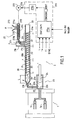
- FIG. 1 shows an installation allowing the manufacture of plastic preforms, from a polymer blend (P) / Additive (A), and comprising a multi-cavity mold 1, the inlet of which is connected to the output of an injection molding machine 2, described in detail below.
- the invention is obviously not limited to the manufacture of preforms plastics, but generally extends to the manufacture of all plastic part by injection into a mold of a mixture polymer (s) / additive (s).
- the mold 1 has two cavities 1 a, being specified that in practice a mold 1 could also include a single cavity 1 has or more commonly a greater number of cavities 1 a allowing the manufacture, at each injection cycle, of a plurality of preforms simultaneously.
- the injection press is a pot press injection, it being specified that a person skilled in the art can easily and immediately transpose the teaching of the description below to any other known type of injection press, and in particular a press direct injection in which the extrusion screw acts as a piston for injecting the material into the mold 1.
- the polymer P could be a mixture of several polymers, or that the injection molding machine could have several polymer gravity intake openings, each opening being dedicated to a given polymer.
- the additive applies to the additive.
- Polymer P consists of any type of polymer known thermoplastic or by any mixture of polymers known thermoplastics, which is capable of being transformed by plasticization in an injection molding machine of the type of FIG. 1, the most commonly used is PET.
- the polymer or polymer mixture P comes at the entrance of the injection molding machine in the form of granules or equivalents, which have preferably been previously dried and which are fed continuously and by gravity, for example from a dryer (not shown in the figures) connected to the inlet of the press inject.
- the temperature of the polymer P at the inlet of the injection molding machine is for example of the order from 140 ° C-150 ° C.
- Additive A is, in the illustrated embodiment, an additive in the form of solid granules, it being specified that in a way general, in the context of the invention, the additive may be only in granular form, but also in pulverulent, liquid, or semi-liquid (paste).
- This additive is for example, and in a non-exclusive and non-limiting manner of the invention, a dye food.
- the extrusion screw 20 is a screw endless equipped with F threads of constant diameter and carried by a body 20b.
- This body 20b consists of a first cylindrical rear portion intended to delimit, with the cylindrical wall of the sheath 21, a zone Z1 so-called feed, a median frustoconical part with increasing section intended to delimit, with the cylindrical wall of the sheath 21, a zone Z2 called compression, and a front cylindrical portion intended to delimit, with the cylindrical wall of the sleeve 21, a so-called transport zone Z3.
- the valve 26 is in the open position.
- Piston 24 is in position initial removed and delimits with the walls of the chamber 23a a volume (or in other words a predetermined quantity) of material to be injected into the mold at each injection cycle.
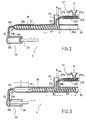
- the extrusion screw 20 is translated to force forward along its longitudinal axis 20a by the thrust member rear 22, into its position, known as the end of transfer, illustrated on the figure 2.
- the screw has thus been moved in translation over a distance substantially corresponding to the length L.
- the melted material (mixture polymer and additive melt A) present in space E is pushed by the extrusion screw 20 acting as a piston and is transferred to the connection conduit 25 and in the chamber 23a of the injection pot 23 which is thus filled with said molten mixture.
- the extrusion screw can simultaneously its forced translation, be rotated on itself or be motionless in rotation.
- the valve 26 is brought to the closed position, and insulates the sheath 21 of the injection pot 23.
- the extrusion screw 20 is rotated on itself along its axis 20a.
- the material (polymer mixture P / additive A) between the screw 20 and the sheath 21 is heated and kneaded, and progresses to gradually towards the front of the sleeve 21 towards the exit 21 b of the sleeve 21, while on the contrary the extrusion screw 20 moves backwards building on the material.
- the polymer P and the additive A melt under the effects combined mechanical shear forces between the sheath 21 and the screw 20, and heating by the heating sleeve 21, said polymer thus undergoing a plasticization and being intimately mixed with the additive A.
- the space E at the front of the extrusion screw 20 gradually increases in filling with melted material (polymer mixture P / additive A).
- the mold 1 is closed, and the piston 24 is pushed in. kind of injecting into the mold the amount of molten material (polymer P / additive A) contained in chamber 23a, then is drawn backwards sort of return to its original position, which determines the volume (quantity) of material injected in each cycle.
- the extrusion screw is stationary in translation and in rotation in its end-of-plasticization position in FIG. 1, awaiting the signal authorizing the start of the transfer phase.
- the duration of this third phase is short compared to the first two phases aforementioned transfer and plasticization.
- the threads F of the screw which are located to the right of the intake opening 21 a of the sleeve 21 are filled with a mixture of polymer and additive, only one small part of molten material progressing forward as of the withdrawal towards the rear of the extrusion screw 20, and being replaced by polymer and additive granules.
- the input rate of polymer by gravity in the plasticization phase is lower.
- the outlet pipe 274 aforementioned on the one hand is partly coaxial with a vertical conduit 21 c, which allows the gravity introduction of the polymer P at the inlet of the sleeve 21 of the extrusion screw 20, and on the other hand makes it possible to convey the additive A to the closer to the intake opening 21a of the sleeve 21.
- the motor 272 rotates the dosing screw 270 with a speed of rotation, which is automatically adjusted by the means 275 via control signal 276.
- Additive A is routed by this screw 270 to the outlet 271 b of the sleeve 271.
- the flow of additive A at the outlet of the sleeve 271 corresponds to the input flow rate of the additive into the sleeve 21 of the extrusion screw 20, and is directly proportional to the speed of rotation of the dosing screw 270.
- the invention is not limited to the implementation of a device for dosing with a dosing screw, but extends to any dosing device comprising a metering member equivalent to the dosing screw, and allowing to adjust automatically the feed rate of additive A at the inlet of the injection molding.
- the dosing device of Figure 1 is suitable for automatically add granular or powdery additive A, but is not on the other hand, it cannot be used to dose a liquid additive. So, and non-limiting manner of the invention, when the additive is in the form liquid, the metering device 27 of FIG. 1 is replaced by a dosing device based on the use of a peristaltic pump, a specific screw dosing pump for liquid or equivalent.
- the calculation module 275a is a programmed module, implemented for example, and in a limiting manner of the invention, in the form of a industrial programmable controller, or an electronic card specific comprising a programmed processing unit based on a microprocessor or microcontroller.
- this calculation module 275a is advantageously synchronized with the actual cycle of the injection molding machine 2, by a synchronization signal (SYNC), coming from the automation of injection press control.
- SYNC synchronization signal
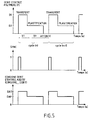
- An example of a timing diagram for this synchronization signal (SYNC) is given in figure 5.
- the above parameters% A and QM are constants which are specific to the production.
- the Dv and Cr parameters are predetermined constants which characterize the injection molding machine.
- the parameter Bd is a specific constant of the polymer P to be injected. For example for PET, Bd is 0.8.
- control means 275 of the device dosage 27 will now be explained with reference to FIGS. 4 and 5.
- control means 275 advantageously allow to take into account the difference previously described between the inlet flow rate of polymer P into the screw of extrusion 20 in the transfer phase and the inlet flow rate of polymer P in the extrusion screw 20 in the plasticization phase, calculating automatically, for each new cycle, and from the parameters mentioned above, two additive input flow instructions DAT and DAP which are specific to the transfer phase and the phase of lamination.
- control means 275 More particularly, with reference to the flowchart of the figure 4, an example of operation of the control means 275 goes to present be described.
- the initial test 40 of the flow diagram of FIG. 4 makes it possible to synchronize the progress of the following stages with a change synchronization signal status (SYNC) characterizing the start of the transfer phase of a cycle (see also timing diagrams in the figure 5).
- SYNC change synchronization signal status
- the calculation module 275 triggers a time delay (step 41), the duration is equal to the aforementioned parameter TT (duration of the transfer phase) and delivers for the variable speed drive 275b (step 42) a setpoint of flow (CONSIGNMENT_DEBIT) which is equal to the variable DAT (setpoint of additive input flow in transfer phase); the current value of this variable DAT was previously calculated (during the third phase waiting for the previous cycle).
- the 275b variable speed drive controls the motor 272 of the dosing screw 270 with a speed (V1) allowing to obtain a real flow rate of additive A at the inlet of the extrusion screw 20 which is substantially equal to the calculated DAT flow setpoint.
- the calculation module 275 triggers a new time delay (step 44) whose duration is equal to the aforementioned parameter TP (duration of the plasticization phase) and delivers for the variable speed drive 275b (step 45) a flow instruction (CONSIGNE_DEBIT) which is equal to the DAP variable (additive input flow setpoint during plasticization); the current value of this DAP variable was previously calculated (during the third waiting phase of the cycle previous).
- variable speed drive 275b drives the motor 272 of the screw dosing 270 with a speed (V2) (which is lower than the above speed V1) making it possible to obtain a real additive flow rate, at the inlet of the screw extrusion 20, which is substantially equal to the calculated DAP setpoint.
- the DAT setpoint which is calculated for each cycle is greater than the DAP setpoint (additive input flow rate in the plasticization phase), said DAT and DAP instructions being calculated automatically so as to keep account for the difference in polymer input flow rate between the transfer (D1) and the plasticization phase (D2), and to obtain at the sleeve 21 of the extrusion screw 20 a concentration of additive in the polymer / additive mixture which is substantially constant over the entire cycle time.
- the calculation module 275 delivers for the variator speed 275b (step 45) a flow instruction (CONSIGNE_DEBIT) which is zero.
- the dosing screw 27 is stopped during this waiting phase.
- the calculation module 275 calculates (FIG. 4 / step 48) the DAT and DAP variables for the operating cycle next.
- the parameters TP and TT which are used by the calculation module 275a, can be predetermined constants.
- the variables TP and / or TT are preferably machine variables, which are automatically calculated at each cycle (in a manner known per se) and supplied to the calculation module 275 by the automation control of the injection press 2. For example, these variables are updated each time new cycle, based on their previous values on a number predetermined from previous cycles, and in particular by calculating the average of their values over a predetermined number of cycles precedents.
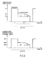
- the means of calculation 275a of the command means so that, from the moment where the compression zone Z2 of the screw 20 is located at the right of the opening intake 21 a of the sleeve 21, said calculation means 275a calculate a setpoint ("CONSIGNE_DEBIT") which decreases for example linearly in time from the current DAP value, according to a predetermined slope depending in particular on the taper of the area of compression Z2 of screw 20.
Landscapes
- Engineering & Computer Science (AREA)
- Manufacturing & Machinery (AREA)
- Mechanical Engineering (AREA)
- Injection Moulding Of Plastics Or The Like (AREA)
Priority Applications (4)
| Application Number | Priority Date | Filing Date | Title |
|---|---|---|---|
| EP20020020872 EP1400332B1 (de) | 2002-09-18 | 2002-09-18 | Verfahren und Vorrichtung zum Dosieren eines Additives bei der Zufuhr einer Spritzgiesspresse, sowie Spritzgiesspresse mit einer Dosiervorrichtung |
| DE60238322T DE60238322D1 (de) | 2002-09-18 | 2002-09-18 | Verfahren und Vorrichtung zum Dosieren eines Additives bei der Zufuhr einer Spritzgiesspresse, sowie Spritzgiesspresse mit einer Dosiervorrichtung |
| PCT/EP2003/007596 WO2004026557A1 (fr) | 2002-09-18 | 2003-07-14 | Procede et dispositif de dosage d'un additif a l'entree d'une presse a injecter, et presse a injecter equipee d'un dispositif de dosage |
| AU2003250054A AU2003250054A1 (en) | 2002-09-18 | 2003-07-14 | Additive-dosing method and device for use at the inlet of an injection-moulding press and dosing device-equipped injection-moulding press |
Applications Claiming Priority (1)
| Application Number | Priority Date | Filing Date | Title |
|---|---|---|---|
| EP20020020872 EP1400332B1 (de) | 2002-09-18 | 2002-09-18 | Verfahren und Vorrichtung zum Dosieren eines Additives bei der Zufuhr einer Spritzgiesspresse, sowie Spritzgiesspresse mit einer Dosiervorrichtung |
Publications (2)
| Publication Number | Publication Date |
|---|---|
| EP1400332A1 true EP1400332A1 (de) | 2004-03-24 |
| EP1400332B1 EP1400332B1 (de) | 2010-11-17 |
Family
ID=31896872
Family Applications (1)
| Application Number | Title | Priority Date | Filing Date |
|---|---|---|---|
| EP20020020872 Expired - Lifetime EP1400332B1 (de) | 2002-09-18 | 2002-09-18 | Verfahren und Vorrichtung zum Dosieren eines Additives bei der Zufuhr einer Spritzgiesspresse, sowie Spritzgiesspresse mit einer Dosiervorrichtung |
Country Status (4)
| Country | Link |
|---|---|
| EP (1) | EP1400332B1 (de) |
| AU (1) | AU2003250054A1 (de) |
| DE (1) | DE60238322D1 (de) |
| WO (1) | WO2004026557A1 (de) |
Cited By (21)
| Publication number | Priority date | Publication date | Assignee | Title |
|---|---|---|---|---|
| EP2257417A4 (de) * | 2008-02-21 | 2011-10-12 | Husky Injection Molding | Verfahren zur senkung des acetaldehydgehalts in einem formartikel |
| CN104526995A (zh) * | 2014-12-17 | 2015-04-22 | 泰瑞机器股份有限公司 | 一种具有清料功能的塑料挤注成型机 |
| WO2018183629A1 (en) * | 2017-03-29 | 2018-10-04 | Maguire Products, Inc. | Dual signal additive feeding method and apparatus |
| US20190118413A1 (en) | 2012-05-31 | 2019-04-25 | Mohawk Industries, Inc. | Systems and methods for manufacturing bulked continuous filament from colored recycled pet |
| US10487422B2 (en) | 2012-05-31 | 2019-11-26 | Aladdin Manufacturing Corporation | Methods for manufacturing bulked continuous filament from colored recycled pet |
| US10493660B2 (en) | 2012-05-31 | 2019-12-03 | Aladdin Manufacturing Corporation | Systems and methods for manufacturing bulked continuous filament |
| US10538016B2 (en) | 2012-05-31 | 2020-01-21 | Aladdin Manufacturing Corporation | Methods for manufacturing bulked continuous carpet filament |
| US10597513B2 (en) | 2013-07-17 | 2020-03-24 | Stephen B. Maguire | Cottonseed oil based additive compositions for plastics molding and extrusion |
| US10647046B2 (en) | 2012-05-31 | 2020-05-12 | Aladdin Manufacturing Corporation | Methods for manufacturing bulked continuous filament |
| US10654211B2 (en) | 2012-05-31 | 2020-05-19 | Aladdin Manufacturing Corporation | Methods for manufacturing bulked continuous filament |
| US10695953B2 (en) | 2012-05-31 | 2020-06-30 | Aladdin Manufacturing Corporation | Methods for manufacturing bulked continuous carpet filament |
| US10751915B2 (en) | 2016-11-10 | 2020-08-25 | Aladdin Manufacturing Corporation | Polyethylene terephthalate coloring systems and methods |
| US10767031B2 (en) | 2013-07-17 | 2020-09-08 | Stephen B. Maguire | Cottonseed oil based liquid color composition and plastics coloring method using the same |
| WO2021044265A1 (en) * | 2019-09-05 | 2021-03-11 | 3M Innovative Properties Company | Method and system of delivering additives for molding |
| US11045979B2 (en) | 2012-05-31 | 2021-06-29 | Aladdin Manufacturing Corporation | Methods for manufacturing bulked continuous filament from recycled PET |
| US11242622B2 (en) | 2018-07-20 | 2022-02-08 | Aladdin Manufacturing Corporation | Bulked continuous carpet filament manufacturing from polytrimethylene terephthalate |
| US11279071B2 (en) | 2017-03-03 | 2022-03-22 | Aladdin Manufacturing Corporation | Method of manufacturing bulked continuous carpet filament |
| US11351747B2 (en) | 2017-01-30 | 2022-06-07 | Aladdin Manufacturing Corporation | Systems and methods for manufacturing bulked continuous filament from colored recycled PET |
| US11473216B2 (en) | 2017-09-15 | 2022-10-18 | Aladdin Manufacturing Corporation | Polyethylene terephthalate coloring systems and methods |
| US11795297B2 (en) | 2013-07-17 | 2023-10-24 | Stephen B. Maguire | Plastics coloring using cottonseed oil-based liquid color compositions |
| US12343903B2 (en) | 2019-06-05 | 2025-07-01 | Aladdin Manufacturing Corporation | Methods for manufacturing bulked continuous carpet filament |
Families Citing this family (2)
| Publication number | Priority date | Publication date | Assignee | Title |
|---|---|---|---|---|
| DE102017126946A1 (de) | 2017-11-16 | 2019-05-16 | Kraussmaffei Technologies Gmbh | Verfahren zur Herstellung von Kunststoff-Formteilen |
| TWI886988B (zh) * | 2024-06-03 | 2025-06-11 | 國立高雄科技大學 | 微型成型裝置 |
Citations (7)
| Publication number | Priority date | Publication date | Assignee | Title |
|---|---|---|---|---|
| JPS6158714A (ja) * | 1984-08-31 | 1986-03-26 | Aida Eng Ltd | 熱可塑性樹脂の計量射出装置 |
| WO1986006321A1 (en) * | 1985-05-02 | 1986-11-06 | Brunel University | Forming articles from composite materials |
| US4678420A (en) * | 1984-02-06 | 1987-07-07 | Inoue-Japax Research Incorporated | Injection molding machine with auxiliary packing means |
| JPH01176540A (ja) * | 1987-12-29 | 1989-07-12 | Meiki Co Ltd | 射出成形機 |
| JPH03251420A (ja) * | 1990-03-01 | 1991-11-08 | Meiki Co Ltd | 射出成形機における液状着色剤の注入制御方法及びそのための注入装置 |
| JPH04156312A (ja) * | 1990-10-20 | 1992-05-28 | Shisuko:Kk | 着色樹脂成形装置 |
| JPH106364A (ja) * | 1996-06-21 | 1998-01-13 | Denki Kagaku Kogyo Kk | 成形品の製造方法 |
-
2002
- 2002-09-18 DE DE60238322T patent/DE60238322D1/de not_active Expired - Lifetime
- 2002-09-18 EP EP20020020872 patent/EP1400332B1/de not_active Expired - Lifetime
-
2003
- 2003-07-14 WO PCT/EP2003/007596 patent/WO2004026557A1/fr not_active Ceased
- 2003-07-14 AU AU2003250054A patent/AU2003250054A1/en not_active Abandoned
Patent Citations (7)
| Publication number | Priority date | Publication date | Assignee | Title |
|---|---|---|---|---|
| US4678420A (en) * | 1984-02-06 | 1987-07-07 | Inoue-Japax Research Incorporated | Injection molding machine with auxiliary packing means |
| JPS6158714A (ja) * | 1984-08-31 | 1986-03-26 | Aida Eng Ltd | 熱可塑性樹脂の計量射出装置 |
| WO1986006321A1 (en) * | 1985-05-02 | 1986-11-06 | Brunel University | Forming articles from composite materials |
| JPH01176540A (ja) * | 1987-12-29 | 1989-07-12 | Meiki Co Ltd | 射出成形機 |
| JPH03251420A (ja) * | 1990-03-01 | 1991-11-08 | Meiki Co Ltd | 射出成形機における液状着色剤の注入制御方法及びそのための注入装置 |
| JPH04156312A (ja) * | 1990-10-20 | 1992-05-28 | Shisuko:Kk | 着色樹脂成形装置 |
| JPH106364A (ja) * | 1996-06-21 | 1998-01-13 | Denki Kagaku Kogyo Kk | 成形品の製造方法 |
Non-Patent Citations (5)
| Title |
|---|
| PATENT ABSTRACTS OF JAPAN vol. 010, no. 222 (M - 504) 2 August 1986 (1986-08-02) * |
| PATENT ABSTRACTS OF JAPAN vol. 013, no. 455 (M - 879) 13 October 1989 (1989-10-13) * |
| PATENT ABSTRACTS OF JAPAN vol. 016, no. 047 (M - 1208) 6 February 1992 (1992-02-06) * |
| PATENT ABSTRACTS OF JAPAN vol. 016, no. 446 (M - 1311) 17 September 1992 (1992-09-17) * |
| PATENT ABSTRACTS OF JAPAN vol. 1998, no. 05 30 April 1998 (1998-04-30) * |
Cited By (49)
| Publication number | Priority date | Publication date | Assignee | Title |
|---|---|---|---|---|
| EP2257417A4 (de) * | 2008-02-21 | 2011-10-12 | Husky Injection Molding | Verfahren zur senkung des acetaldehydgehalts in einem formartikel |
| US8794818B2 (en) | 2008-02-21 | 2014-08-05 | Husky Injection Molding Systems Ltd. | Method of decreasing acetaldehyde level in a molded article |
| US11780145B2 (en) | 2012-05-31 | 2023-10-10 | Aladdin Manufacturing Corporation | Method for manufacturing recycled polymer |
| US10695953B2 (en) | 2012-05-31 | 2020-06-30 | Aladdin Manufacturing Corporation | Methods for manufacturing bulked continuous carpet filament |
| US20190118413A1 (en) | 2012-05-31 | 2019-04-25 | Mohawk Industries, Inc. | Systems and methods for manufacturing bulked continuous filament from colored recycled pet |
| US10487422B2 (en) | 2012-05-31 | 2019-11-26 | Aladdin Manufacturing Corporation | Methods for manufacturing bulked continuous filament from colored recycled pet |
| US10493660B2 (en) | 2012-05-31 | 2019-12-03 | Aladdin Manufacturing Corporation | Systems and methods for manufacturing bulked continuous filament |
| US10532495B2 (en) | 2012-05-31 | 2020-01-14 | Aladdin Manufacturing Corporation | Methods for manufacturing bulked continuous filament from recycled PET |
| US10532496B2 (en) | 2012-05-31 | 2020-01-14 | Aladdin Manufacturing Corporation | Methods for manufacturing bulked continuous filament |
| US10538016B2 (en) | 2012-05-31 | 2020-01-21 | Aladdin Manufacturing Corporation | Methods for manufacturing bulked continuous carpet filament |
| US12420453B2 (en) | 2012-05-31 | 2025-09-23 | Aladdin Manufacturing Corporation | Systems for manufacturing bulked continuous carpet filament |
| US10639818B2 (en) | 2012-05-31 | 2020-05-05 | Aladdin Manufacturing Corporation | Methods for manufacturing bulked continuous filament |
| US10647046B2 (en) | 2012-05-31 | 2020-05-12 | Aladdin Manufacturing Corporation | Methods for manufacturing bulked continuous filament |
| US10654211B2 (en) | 2012-05-31 | 2020-05-19 | Aladdin Manufacturing Corporation | Methods for manufacturing bulked continuous filament |
| US11273579B2 (en) | 2012-05-31 | 2022-03-15 | Aladdin Manufacturing Corporation | Systems and methods for manufacturing bulked continuous filament |
| US10744681B2 (en) | 2012-05-31 | 2020-08-18 | Aladdin Manufacturing Corporation | Methods for manufacturing bulked continuous filament |
| US12215200B2 (en) | 2012-05-31 | 2025-02-04 | Aladdin Manufacturing Corporation | Methods for manufacturing bulked continuous filament |
| US12172356B2 (en) | 2012-05-31 | 2024-12-24 | Aladdin Manufacturing Corporation | Methods for manufacturing bulked continuous filament |
| US12109730B2 (en) | 2012-05-31 | 2024-10-08 | Aladdin Manufacturing Corporation | Systems and methods for manufacturing bulked continuous filament |
| US12070886B2 (en) | 2012-05-31 | 2024-08-27 | Aladdin Manufacturing Corporation | Systems and methods for manufacturing bulked continuous filament |
| US11007673B2 (en) | 2012-05-31 | 2021-05-18 | Aladdin Manufacturing Corporation | Methods for manufacturing bulked continuous filament from colored recycled PET |
| US11045979B2 (en) | 2012-05-31 | 2021-06-29 | Aladdin Manufacturing Corporation | Methods for manufacturing bulked continuous filament from recycled PET |
| US11911930B2 (en) | 2012-05-31 | 2024-02-27 | Aladdin Manufacturing Corporation | Methods for manufacturing bulked continuous filament from recycled PET |
| US11179868B2 (en) | 2012-05-31 | 2021-11-23 | Aladdin Manufacturing Corporation | Systems and methods for manufacturing bulked continuous filament |
| US11724418B2 (en) | 2012-05-31 | 2023-08-15 | Aladdin Manufacturing Corporation | Methods for manufacturing bulked continuous carpet filament |
| US11426913B2 (en) | 2012-05-31 | 2022-08-30 | Aladdin Manufacturing Corporation | Methods for manufacturing bulked continuous filament |
| US11427694B2 (en) | 2012-05-31 | 2022-08-30 | Aladdin Manufacturing Corporation | Methods for manufacturing bulked continuous filament |
| US11292174B2 (en) | 2012-05-31 | 2022-04-05 | Aladdin Manufacturing Corporation | Systems and methods for manufacturing bulked continuous filament |
| US11795297B2 (en) | 2013-07-17 | 2023-10-24 | Stephen B. Maguire | Plastics coloring using cottonseed oil-based liquid color compositions |
| US10597513B2 (en) | 2013-07-17 | 2020-03-24 | Stephen B. Maguire | Cottonseed oil based additive compositions for plastics molding and extrusion |
| US11602883B2 (en) | 2013-07-17 | 2023-03-14 | Riverdale Global, Llc | Cottonseed oil liquid color composition and method |
| US10767031B2 (en) | 2013-07-17 | 2020-09-08 | Stephen B. Maguire | Cottonseed oil based liquid color composition and plastics coloring method using the same |
| US10919206B2 (en) | 2013-07-17 | 2021-02-16 | Stephen B. Maguire | Cottonseed oil based liquid color composition and plastics coloring method using the same |
| CN104526995A (zh) * | 2014-12-17 | 2015-04-22 | 泰瑞机器股份有限公司 | 一种具有清料功能的塑料挤注成型机 |
| US10751915B2 (en) | 2016-11-10 | 2020-08-25 | Aladdin Manufacturing Corporation | Polyethylene terephthalate coloring systems and methods |
| US11840039B2 (en) | 2017-01-30 | 2023-12-12 | Aladdin Manufacturing Corporation | Systems and methods for manufacturing bulked continuous filament from colored recycled PET |
| US12420509B2 (en) | 2017-01-30 | 2025-09-23 | Aladdin Manufacturing Corporation | Systems and methods for manufacturing bulked continuous filament from colored recycled PET |
| US11351747B2 (en) | 2017-01-30 | 2022-06-07 | Aladdin Manufacturing Corporation | Systems and methods for manufacturing bulked continuous filament from colored recycled PET |
| US11279071B2 (en) | 2017-03-03 | 2022-03-22 | Aladdin Manufacturing Corporation | Method of manufacturing bulked continuous carpet filament |
| WO2018183629A1 (en) * | 2017-03-29 | 2018-10-04 | Maguire Products, Inc. | Dual signal additive feeding method and apparatus |
| US20210237324A1 (en) * | 2017-03-29 | 2021-08-05 | Maguire Products, Inc. | Dual signal additive feeding method and apparatus |
| US11618973B2 (en) | 2017-09-15 | 2023-04-04 | Aladdin Manufacturing Corporation | Polyethylene terephthalate coloring systems and methods |
| US11473216B2 (en) | 2017-09-15 | 2022-10-18 | Aladdin Manufacturing Corporation | Polyethylene terephthalate coloring systems and methods |
| US11242622B2 (en) | 2018-07-20 | 2022-02-08 | Aladdin Manufacturing Corporation | Bulked continuous carpet filament manufacturing from polytrimethylene terephthalate |
| US11926930B2 (en) | 2018-07-20 | 2024-03-12 | Aladdin Manufacturing Corporation | Bulked continuous carpet filament manufacturing from polytrimethylene terephthalate |
| US12595594B2 (en) | 2018-07-20 | 2026-04-07 | Aladdin Manufacturing Corporation | Bulked continuous carpet filament manufacturing from polytrimethylene terephthalate |
| US12343903B2 (en) | 2019-06-05 | 2025-07-01 | Aladdin Manufacturing Corporation | Methods for manufacturing bulked continuous carpet filament |
| WO2021044265A1 (en) * | 2019-09-05 | 2021-03-11 | 3M Innovative Properties Company | Method and system of delivering additives for molding |
| CN114340868A (zh) * | 2019-09-05 | 2022-04-12 | 3M创新有限公司 | 递送用于模塑的添加剂的方法和系统 |
Also Published As
| Publication number | Publication date |
|---|---|
| DE60238322D1 (de) | 2010-12-30 |
| AU2003250054A1 (en) | 2004-04-08 |
| WO2004026557A1 (fr) | 2004-04-01 |
| EP1400332B1 (de) | 2010-11-17 |
Similar Documents
| Publication | Publication Date | Title |
|---|---|---|
| EP1400332B1 (de) | Verfahren und Vorrichtung zum Dosieren eines Additives bei der Zufuhr einer Spritzgiesspresse, sowie Spritzgiesspresse mit einer Dosiervorrichtung | |
| EP0605781B1 (de) | Verfahren und Apparat zum kontinuierlichen Mischen von Kautschuk | |
| US6241932B1 (en) | Method and system for reducing polymer degradation products in two stage injection molding machines | |
| EP0541441B1 (de) | Herstellungsverfahren zum Formen eines Verbundproduktes | |
| JP5894336B2 (ja) | 射出成形方法、及び、射出成形装置 | |
| US20160009010A1 (en) | Injection molding apparatus and injection molding method | |
| JPH04219221A (ja) | バリヤスクリュ | |
| FR2821525A1 (fr) | Procede et installation de preparation en continu de produits alimentaires sous forme de pellets expansables | |
| FR3093457A1 (fr) | Machine de Mélangeage et d’Extrusion à Bi-Vis avec Éléments Amovibles | |
| US20040108611A1 (en) | Injecting liquid additives into plastic extruders | |
| EP0630810A1 (de) | Verfahren und Gerät zur Volumendosierung pastöser Massen | |
| EP0325076A1 (de) | Verfahren und Vorrichtung zum Spritzgiessen von gemischten Stoffen | |
| FR2572899A1 (fr) | Procede et installation de fabrication d'un produit fourre | |
| EP1133384A1 (de) | Verfahren und vorrichtung zur herstellung eines vorformlings durch benutzung von trocknungsmitteln, und aus diesem vorformling hergestellter kunststoffbehälter | |
| JP2010005840A (ja) | 射出成形機の制御方法および射出成形機の射出装置 | |
| FR3066135B1 (fr) | Production de recipients avec recyclage par extrudeuse bivis | |
| ES2354812T3 (es) | Procedimiento y dispositivo de dosificación de un aditivo a la entrada de una prensa de inyectar, y prensa de inyectar equipada de un dispositivo de dosificación. | |
| CN116749428A (zh) | 一种防堵式注塑机 | |
| EP0311520A1 (de) | Verfahren und Maschine zur Herstellung eines Endproduktes mittels Extrusion, ausgehend von einem thermoplastischen extrudierfähigen Material hygroskopischer Natur | |
| FR2599294A1 (fr) | Appareil d'extrusion a deux extrudeuses | |
| FR2693677A1 (fr) | Procédé, vis sans fin et presse pour l'injection de charges successives de matière plastique à mouler. | |
| BE568274A (de) | ||
| CH425186A (fr) | Procédé de moulage de matières plastiques, et dispositif pour la mise en oeuvre de ce procédé | |
| FR2794398A1 (fr) | Procede et dispositif de moulage d'une piece bi-matiere avec brassage de la matiere de peau | |
| BE520968A (de) |
Legal Events
| Date | Code | Title | Description |
|---|---|---|---|
| PUAI | Public reference made under article 153(3) epc to a published international application that has entered the european phase |
Free format text: ORIGINAL CODE: 0009012 |
|
| AK | Designated contracting states |
Kind code of ref document: A1 Designated state(s): AT BE BG CH CY CZ DE DK EE ES FI FR GB GR IE IT LI LU MC NL PT SE SK TR |
|
| AX | Request for extension of the european patent |
Extension state: AL LT LV MK RO SI |
|
| 17P | Request for examination filed |
Effective date: 20040823 |
|
| AKX | Designation fees paid |
Designated state(s): DE ES FR GB IT |
|
| 17Q | First examination report despatched |
Effective date: 20081218 |
|
| GRAP | Despatch of communication of intention to grant a patent |
Free format text: ORIGINAL CODE: EPIDOSNIGR1 |
|
| GRAS | Grant fee paid |
Free format text: ORIGINAL CODE: EPIDOSNIGR3 |
|
| GRAA | (expected) grant |
Free format text: ORIGINAL CODE: 0009210 |
|
| RAP1 | Party data changed (applicant data changed or rights of an application transferred) |
Owner name: AMCOR LIMITED |
|
| AK | Designated contracting states |
Kind code of ref document: B1 Designated state(s): DE ES FR GB IT |
|
| REG | Reference to a national code |
Ref country code: GB Ref legal event code: FG4D Free format text: NOT ENGLISH |
|
| REF | Corresponds to: |
Ref document number: 60238322 Country of ref document: DE Date of ref document: 20101230 Kind code of ref document: P |
|
| REG | Reference to a national code |
Ref country code: ES Ref legal event code: FG2A Effective date: 20110308 |
|
| PLBE | No opposition filed within time limit |
Free format text: ORIGINAL CODE: 0009261 |
|
| STAA | Information on the status of an ep patent application or granted ep patent |
Free format text: STATUS: NO OPPOSITION FILED WITHIN TIME LIMIT |
|
| 26N | No opposition filed |
Effective date: 20110818 |
|
| REG | Reference to a national code |
Ref country code: DE Ref legal event code: R097 Ref document number: 60238322 Country of ref document: DE Effective date: 20110818 |
|
| PGFP | Annual fee paid to national office [announced via postgrant information from national office to epo] |
Ref country code: GB Payment date: 20120828 Year of fee payment: 11 |
|
| PGFP | Annual fee paid to national office [announced via postgrant information from national office to epo] |
Ref country code: IT Payment date: 20120829 Year of fee payment: 11 Ref country code: FR Payment date: 20121004 Year of fee payment: 11 Ref country code: DE Payment date: 20120827 Year of fee payment: 11 Ref country code: ES Payment date: 20120910 Year of fee payment: 11 |
|
| GBPC | Gb: european patent ceased through non-payment of renewal fee |
Effective date: 20130918 |
|
| REG | Reference to a national code |
Ref country code: DE Ref legal event code: R119 Ref document number: 60238322 Country of ref document: DE Effective date: 20140401 |
|
| REG | Reference to a national code |
Ref country code: FR Ref legal event code: ST Effective date: 20140530 |
|
| PG25 | Lapsed in a contracting state [announced via postgrant information from national office to epo] |
Ref country code: GB Free format text: LAPSE BECAUSE OF NON-PAYMENT OF DUE FEES Effective date: 20130918 |
|
| PG25 | Lapsed in a contracting state [announced via postgrant information from national office to epo] |
Ref country code: FR Free format text: LAPSE BECAUSE OF NON-PAYMENT OF DUE FEES Effective date: 20130930 Ref country code: DE Free format text: LAPSE BECAUSE OF NON-PAYMENT OF DUE FEES Effective date: 20140401 Ref country code: IT Free format text: LAPSE BECAUSE OF NON-PAYMENT OF DUE FEES Effective date: 20130918 |
|
| REG | Reference to a national code |
Ref country code: ES Ref legal event code: FD2A Effective date: 20150504 |
|
| PG25 | Lapsed in a contracting state [announced via postgrant information from national office to epo] |
Ref country code: ES Free format text: LAPSE BECAUSE OF NON-PAYMENT OF DUE FEES Effective date: 20130919 |