EP1400357A1 - Rouleau d'impression avec indicateur d'usure et procédé pour déterminer l'usure sur des rouleaux ou manches d'impression ou anilox - Google Patents
Rouleau d'impression avec indicateur d'usure et procédé pour déterminer l'usure sur des rouleaux ou manches d'impression ou anilox Download PDFInfo
- Publication number
- EP1400357A1 EP1400357A1 EP03020910A EP03020910A EP1400357A1 EP 1400357 A1 EP1400357 A1 EP 1400357A1 EP 03020910 A EP03020910 A EP 03020910A EP 03020910 A EP03020910 A EP 03020910A EP 1400357 A1 EP1400357 A1 EP 1400357A1
- Authority
- EP
- European Patent Office
- Prior art keywords
- wear
- roll
- indicator
- colorant
- cells
- Prior art date
- Legal status (The legal status is an assumption and is not a legal conclusion. Google has not performed a legal analysis and makes no representation as to the accuracy of the status listed.)
- Withdrawn
Links
- 238000000034 method Methods 0.000 title claims abstract description 20
- 238000007774 anilox coating Methods 0.000 title description 6
- 230000007246 mechanism Effects 0.000 claims abstract description 22
- 239000000758 substrate Substances 0.000 claims abstract description 15
- 230000002596 correlated effect Effects 0.000 claims abstract 3
- 239000003086 colorant Substances 0.000 claims description 43
- 238000005524 ceramic coating Methods 0.000 claims description 10
- 230000008569 process Effects 0.000 claims description 3
- 239000011248 coating agent Substances 0.000 claims description 2
- 238000000576 coating method Methods 0.000 claims description 2
- 230000003292 diminished effect Effects 0.000 claims description 2
- 230000000779 depleting effect Effects 0.000 claims 1
- 238000001514 detection method Methods 0.000 abstract description 5
- CURLTUGMZLYLDI-UHFFFAOYSA-N Carbon dioxide Chemical compound O=C=O CURLTUGMZLYLDI-UHFFFAOYSA-N 0.000 description 5
- 239000000919 ceramic Substances 0.000 description 4
- 229910002092 carbon dioxide Inorganic materials 0.000 description 3
- 239000001569 carbon dioxide Substances 0.000 description 3
- 230000009467 reduction Effects 0.000 description 3
- 230000000007 visual effect Effects 0.000 description 3
- 238000004519 manufacturing process Methods 0.000 description 2
- 229910000831 Steel Inorganic materials 0.000 description 1
- WGLPBDUCMAPZCE-UHFFFAOYSA-N Trioxochromium Chemical compound O=[Cr](=O)=O WGLPBDUCMAPZCE-UHFFFAOYSA-N 0.000 description 1
- 230000005856 abnormality Effects 0.000 description 1
- 230000004888 barrier function Effects 0.000 description 1
- 230000008901 benefit Effects 0.000 description 1
- 230000015572 biosynthetic process Effects 0.000 description 1
- 229910000423 chromium oxide Inorganic materials 0.000 description 1
- 238000010276 construction Methods 0.000 description 1
- 230000003628 erosive effect Effects 0.000 description 1
- 238000005530 etching Methods 0.000 description 1
- 238000010147 laser engraving Methods 0.000 description 1
- 229910052751 metal Inorganic materials 0.000 description 1
- 239000002184 metal Substances 0.000 description 1
- 238000012986 modification Methods 0.000 description 1
- 230000004048 modification Effects 0.000 description 1
- 230000000737 periodic effect Effects 0.000 description 1
- 229910001220 stainless steel Inorganic materials 0.000 description 1
- 239000010935 stainless steel Substances 0.000 description 1
- 239000010959 steel Substances 0.000 description 1
- 239000000126 substance Substances 0.000 description 1
Images



Classifications
-
- B—PERFORMING OPERATIONS; TRANSPORTING
- B41—PRINTING; LINING MACHINES; TYPEWRITERS; STAMPS
- B41F—PRINTING MACHINES OR PRESSES
- B41F31/00—Inking arrangements or devices
- B41F31/26—Construction of inking rollers
-
- B—PERFORMING OPERATIONS; TRANSPORTING
- B41—PRINTING; LINING MACHINES; TYPEWRITERS; STAMPS
- B41F—PRINTING MACHINES OR PRESSES
- B41F31/00—Inking arrangements or devices
- B41F31/02—Ducts, containers, supply or metering devices
- B41F31/027—Ink rail devices for inking ink rollers
-
- Y—GENERAL TAGGING OF NEW TECHNOLOGICAL DEVELOPMENTS; GENERAL TAGGING OF CROSS-SECTIONAL TECHNOLOGIES SPANNING OVER SEVERAL SECTIONS OF THE IPC; TECHNICAL SUBJECTS COVERED BY FORMER USPC CROSS-REFERENCE ART COLLECTIONS [XRACs] AND DIGESTS
- Y10—TECHNICAL SUBJECTS COVERED BY FORMER USPC
- Y10S—TECHNICAL SUBJECTS COVERED BY FORMER USPC CROSS-REFERENCE ART COLLECTIONS [XRACs] AND DIGESTS
- Y10S507/00—Earth boring, well treating, and oil field chemistry
- Y10S507/906—Solid inorganic additive in defined physical form
Definitions
- Modern printing rolls may be formed in a number of ways, including by overcoating a smooth metallic core with a metal layer, followed by applying an outer ceramic coating.
- the outer ceramic coating then may be engraved using a laser to form a desired cell pattern in the ceramic.
- Various printing rolls or sleeves exemplified by anilox rolls, engraved rolls, form rolls, meter rolls, knurled rolls, ink applicator rolls, sleeves, ink transfer rolls, and the like may utilize the present invention if they wear during use.
- Printing rolls and/or sleeves typically include a series of engraved cells or the like upon their outer surface. The cells are configured to receive and transfer colorants such as ink in the formation of an image or coloration on a substrate.
- ink from a reservoir is transferred to a roll, such as an anilox roll.
- the anilox roll then transfers the ink to a printing plate, which may be mounted to the surface of a print cylinder.
- the web or substrate is printed when the print cylinder and inked printing plate roll over the web, transferring the image to the web. This process may be repeated thousands of times.
- the outer surface of printing rolls may experience significant amounts of wear, which are the subject of this invention.
- cells in the outer surface of the roll are worn away and their volumes are reduced. These cells, which sometimes form an inverted pyramid or a hexagon, supply a fixed quantity of ink that is passed to the web or substrate during printing, based on the volume of the cell.
- Printing personnel may compensate for such wear by adjusting the intensity of ink applied to the roll.
- the amount of wear has been estimated, and the ink concentration applied to the roll was periodically adjusted to increase the intensity of the ink, thereby compensating for such wear.
- To determine the actual amount of wear it has usually been required that the roll be removed from service, and examined with a magnifying apparatus, such as a microscope.
- the periodic compensation for roll wear to maintain a consistent image is a significant challenge in conducting such printing processes.
- What is needed in the printing industry is an apparatus and method for accurately and quickly determining the amount of wear that has been experienced by a roll.
- An apparatus that provides to printing personnel updated or "real time” information regarding the amount of wear experienced by the outer surface of such rolls would be very desirable.
- Such an apparatus and method of use of same could enable more accurate and more convenient adjustment of the amount of colorant or ink applied, thereby improving the continuity of high quality, consistent printing.
- An apparatus or method that could supply wear data or information without requiring that the roll be dismounted and examined by magnification devices would be particularly useful.
- the print machinery is out of alignment, resulting in uneven wear along the length of the roll, or a roll when provided is "out of round". It would also be important for printing personnel to be aware of such abnormalities which can lend to off quality production. Wear indicating apparatus and methods that could alert to uneven wear, out of round rolls and the like would be therefore quite useful.
- a printing device for applying colorant to a substrate receives colorant from a reservoir to a substrate.
- a wear indicator mechanism is configured to detect wear and transfer the colorant of the outer circumferential surface of the roll.
- the roll may be an anilox roll with a ceramic coating on its outer surface.
- an outer sleeve is applied to the exterior surface.
- a system for determining the amount of wear that has been experienced by a roll or sleeve in a printing system is provided.
- a reservoir supplies colorant to the roll which is metered by a doctor blade, with respect to the plurality of transferring cells located on the outer surface of the roll.
- the transferring cells receive colorant from the reservoir and transfer the colorant to a substrate.
- One or more doctor blades wipe across the surface of the roll, metering colorant to the transferring cells.
- the doctor blades function as a dam or barrier for the colorant reservoir.
- the printing roll rotates while bearing against the doctor blade(s), and the portion of the outer circumferential surface on the roll that is engaged by a doctor blade defines a wear surface, and does wear during use.
- a wear indicator mechanism or means provided on the outer circumferential surface of the roll measures the amount of wear experienced by the roll.
- the wear indicator includes a plurality of indicator cells at various predetermined depths upon the outer circumferential surface of the roll.
- a single indicator cell is employed.
- the indicator cells may be provided in alignment with a wear scale, which provides numerical or other indication of the amount of wear that has been experienced by the wear surface of a roll.
- other embodiments do not employ a scale or other indicia, but instead rely upon erasure of a textured surface to indicate the degree of wear upon a roll.
- a method for detecting the amount of wear experienced by a printing roll includes providing a cylindrical roll having a wear-detection mechanism configured to detect depletion of the outer surface of the cylindrical roll.
- the roll is rotated, thereby transferring ink from a supply to a substrate.
- the wear indicator mechanism makes it possible to observe the amount of roll wear.
- a printing system generally 20 is shown in which a colorant supply unit 21 supplies colorant to a roll 22 .
- Colorant supply unit 21 transfers colorant which is held within a reservoir 27 of a body 26 .
- a first doctor blade 28 and a second doctor blade 29 (shown in phantom in Figure 1 ) form the limits of reservoir 27 , and bear against the outer surface of the roll 22 to meter colorant into transferring cells of the roll (cells not shown).
- the portion of the roll subject to the respective first and second doctor blades 28-29 is shown as wear surface zone 39 in Figure 3 .
- Figure 1 shows one embodiment of a wear indicator mechanism generally 25 which will be fully described herein.
- Colorant within the reservoir 27 may be ink or any other substance that provides a color or visually perceptible image. Ink is typically used as a colorant in such apparatus.
- FIG 2 a cross sectional view along lines 2-2 of Figure 1 is provided.
- a clamping bar 30 holds in place first doctor blade 28 , which bears against roll 22 .
- the wear indicator mechanism 25 is shown in phantom passing beneath the first doctor blade 28 .
- Alignment pin 31 is shown at the upper portion of the first doctor blade 28 , and a bolt 32 holds the clamping bar 30 in place against the body 26 of the inking unit 34 , though any suitable arrangement for securing doctor blades 28-29 may be provided.
- An elastic seal 33 is provided between the first doctor blade 28 and the body 26 to seal reservoir 27 at that point. In other applications, an outer sleeve is employed.
- the use of "roll” herein shall be construed to also cover the use of transfer sleeves and the like.
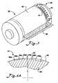
- FIG 3 shows a perspective view of a roll 22 which has been removed from a printing system such as 20 for purposes of illustration, and which forms an embodiment of the invention.
- the outer circumferential surface 40 of the roll 22 carries a wear indicator mechanism 25 .
- the wear surface zone 39 is shown as that portion of the roll contacting colorant between and/or beneath respective doctor blades 28-29 .
- a wear strip 41 is provided in the outer surface of roll 22 just outside the intended image area.
- Wear strip 41 includes of a plurality of wear indicator cells 43a-g (see Figure 4A ).
- the wear indicator cells 43a-g each correlate with a depletion indicia or value 44 juxtaposed thereto.
- the wear indicator cells 43a-g and depletion indicia or values 44 typically are positioned just outside the image pattern (but still within the wear zone of the first doctor blade 28 ) though could be placed within the image pattern if acceptable.
- the printed or engraved depletion indicia or values 44 are generally unaffected by wear upon wear surface zone 39 of roll 22 , but again, could be worn away along with its corresponding cell or cell portion.
- the depletion indicia or values 44 may be provided in the form of a depletion scale, using numerals, or other indicia.
- the depletion indicia or values 44 (or scale) may provide the percentage of wear that has been experienced by a roll 22 .
- the first wear cell to the left of "10" represents about 10 percent of the original colorant transferring via the transferring cell, and when worn off, indicates that the cells have lost about 10 percent of their depth or the like. This is only one means of detecting wear.
- Depletion values 44 may not be necessary if an operator has knowledge of the amount of wear represented by each indicator cell 43a-g . The operator may simply note the number of wear indicator cells 43a-g which are absent or remaining at any given time and will thereby ascertain the degree of wear. In some embodiments, a cross-hatching or texture may be provided upon the lower surface of indicator cells, and when such texture is removed, immediately provides a visual cue to the degree of wear.
- FIG 4A a partial cross sectional view of the wear strip 41 of the wear indicator mechanism 25 is shown.
- Engraved areas may be provided on the outer surface of the roll 22 .
- the engraved areas are cut into a hardened outer surface of the roll using a laser, such as a carbon dioxide laser.
- wear indicator cell 43a may be engraved to a predetermined depth, while wear indicator cell 43b is engraved to an even greater depth. Successively greater depths have been engraved into the outer circumferential surface 40 of the roll as one proceeds along the outer periphery of the roll from 43a-43g.
- the deepest and last wear indicator cell 43g is shown near the far right side of the Figure.
- wear indicator cells 43a-g there is no limit to the number of wear indicator cells 43a-g that may be provided. Furthermore, the wear indicator cells 43a-g could be provided within only one indicator cell, or could be spread among many such indicator cells. Etching or other suitable technique may be employed instead of engraving, to produce the wear indicator cell or cells.
- Figure 4B shows the roll previously seen in Figure 4A , except that the roll has experienced wear which has depleted the outer circumferential surface 40 as shown down to the depth of indicator cell 43d.
- wear indicator cells 43a, 43b, and 43c are no longer visible, having been worn away during operation of roll 22.
- an operator observing roll 22 which is shown in Figure 4B could readily observe that the wear indicator cell 43d is in alignment with a roll depletion value of about "40" (for example, as shown in Figure 3 ).
- indicator cells 43a-g it is not always necessary to use numerical values adjacent to indicator cells 43a-g , because the mere absence of such indicator cells 43a-g may indicate to an experienced operator that a given amount of wear has occurred. That is, an operator who is aware that rolls begin with a total of seven wear indicator cells 43a-g (as an example) would know that by observing only five of them, that two have been worn off, indicating to him a certain value of wear by the absence of a predetermined number of such positions 43a-g .
- FIG. 4C illustrates yet another embodiment of the invention in which a wear detection means 64 includes a single wear indicator cell 65 .
- Wear indicator cell 65 is configured to have a predetermined depth. When the depth is diminished by wear, a visual indicator is provided to reveal the amount of wear of said wear indicator cell 65 upon the printing roll 66 .
- the visual indication may be provided by the loss of a visible texture or other marking which is prepositioned upon the sloping surface 69 of the wear indicator cell 65.
- the sloping surface 69 extends from the outer circumferential surface 67 of the printing roll 66 to a bottom point 68 of the wear indicator cell 65 . The absence of such a texture would shorten the total length of the sloping surface 69 , indicating to an operator the degree of wear that has been experienced by printing roll 66 .
- FIG 4D yet another embodiment of the invention is illustrated in a top plan view, with a single indicator cell 74 providing a wear detection means by employing multiple depth portions or steps 75a-d in a concentric circular pattern upon the outer circumferential surface 77 of the printing roll 78 .
- a bottom point 76 is centered, and forms the deepest portion of the indicator cell 74 .
- a cross section of the indicator cell 74 of Figure 4D taken along line 4E-4E is provided in Figure 4E. Wear experienced by indicator cell 74 would deplete the printing roll 78 by first erasing depth position 75a, which would simply make the indicator cell 74 appear smaller in diameter.
- the size of the indicator cell 74 in total visible diameter would indicate the degree of wear experienced by the printing roll 78.
- FIG. 5 illustrates further embodiments of the invention in which it is possible to provide a roll 150 with wear indicator means 152a-h .
- wear indicator means 152a-d are located on the first end 154 of the roll 150
- wear indicator mechanism or means 152e-h are shown on the second end 155 of the roll 150 .
- Wear experienced by the outer circumferential surface 156 of the roll 150 may be measured at various positions around the roll, at both ends of the roll, or both.
- Wear indicator sets 152a-h could be provided in differing numbers of sets and at different locations around the circumference of the roll. For example, as shown in Figure 5 such wear indicator sets 152a-d are provided at 90 degrees from each other. In other applications, such wear indicator sets 152a-h may be provided at differing degree intervals, e.g. when three wear indicator sets are positioned around a roll 22 . Such sets 152a-h may be equally spaced to correlate evenness of wear around the roll.
- Figure 5 also illustrates the wear indicator sets 152a-h at both ends of a roll, e.g. 152a and 152e . Using such an arrangement, one can observe the two wear strips during use and ascertain the location at which wear is even along the roll.
- Figure 5 shows in combination two different features, that is, one feature of providing said wear indicator sets 152a-h on both ends of a roll, and a second feature providing said wear indicator sets in spaced groups around the circumference of a roll.
- One or both features may be employed independently.
- Some embodiments of the invention may employ both the first and second feature, as does the roll in Figure 5 .
- Printing rolls include transferring cells or transferring cell structures that may be of several types, including, without limitation, trihelical, pyramidal, quadrangular, hexagonal, or hexagonal. Other shapes are possible as well.
- a pyramidal shaped cell may be employed in the invention. Transferring cells usually are very small, and are not illustrated in Figures 1-5 although it is understood that such transferring cells appear on the outer circumferential surface of such printing rolls.
- Rolls may be provided in many different forms in the application of the invention. The invention of this application is not limited to any particular type of roll, but may apply to numerous roll types.
- Laser engraved rolls may include plasma sprayed ceramic coating (e.g. chromium oxide) that is ground and honed to a very smooth finish.
- a ceramic coating typically is extremely hard. Hardness is widely used as a guide to strength, wear, and erosion resistance of a coating.
- lasers of any type may be used in laser engraving.
- CO 2 carbon dioxide
- lasers can be used to manufacture laser engraved rolls.
- Such lasers may be used to generate pulses of energy, whereby each pulse is responsible for producing an impression in the ceramic.
- a laser beam must be focused upon the ceramic surface using special lenses.
- Commercially available lasers may be used available to persons of skill in the art. It should be understood, however, that the present invention is not limited to laser cut rolls. Any roll with cells that wear could be employed regardless of how the cells are processed. Just by way of example cells (both colorant transfer and wear indicator cells) could be either engraved, milled or the like.
- Doctor blades are typically installed near the edge of the roll and are subject to significant pressure. For that reason, they typically are made of steel, such as stainless steel.
- a wear strip 41 (see Figure 3 , as example).
- the wear strip 41 includes a plurality of engraved positions or cells at varying depths upon the outer circumferential surface of the roll.
- the wear indicator cells 43a-g may be provided in alignment with a depletion scale, enabling correlation of positions of the depletable wear strip with depletion scale values. In this way, an indication of the amount of wear experienced by a roll is provided.
- experienced operators may readily observe the degree of wear upon a roll simply by noting the number of wear indicator cells 43a-g that have been worn off during roll usage. If an operator knows the number of indicator cells 43a-g that are provided upon a new roll, he or she may immediately know the degree of wear without the necessity to dismount the roll and/or observe the cells of a roll under a high magnification microscope, which is a significant operational advantage.
Landscapes
- Lubricants (AREA)
- Inking, Control Or Cleaning Of Printing Machines (AREA)
- Colloid Chemistry (AREA)
Applications Claiming Priority (2)
| Application Number | Priority Date | Filing Date | Title |
|---|---|---|---|
| US247528 | 1999-02-10 | ||
| US10/247,528 US6786153B2 (en) | 2002-09-19 | 2002-09-19 | Printing rolls having wear indicators and methods for determining wear of printing and anilox rolls and sleeves |
Publications (1)
| Publication Number | Publication Date |
|---|---|
| EP1400357A1 true EP1400357A1 (fr) | 2004-03-24 |
Family
ID=31946438
Family Applications (1)
| Application Number | Title | Priority Date | Filing Date |
|---|---|---|---|
| EP03020910A Withdrawn EP1400357A1 (fr) | 2002-09-19 | 2003-09-16 | Rouleau d'impression avec indicateur d'usure et procédé pour déterminer l'usure sur des rouleaux ou manches d'impression ou anilox |
Country Status (2)
| Country | Link |
|---|---|
| US (3) | US6786153B2 (fr) |
| EP (1) | EP1400357A1 (fr) |
Families Citing this family (52)
| Publication number | Priority date | Publication date | Assignee | Title |
|---|---|---|---|---|
| US7651983B2 (en) * | 1996-07-24 | 2010-01-26 | M-I L.L.C. | Reduced abrasiveness with micronized weighting material |
| US7169738B2 (en) * | 2004-06-03 | 2007-01-30 | M-I L.L.C. | Method of using a sized barite as a weighting agent for drilling fluids |
| US20030203822A1 (en) * | 1996-07-24 | 2003-10-30 | Bradbury Andrew J. | Additive for increasing the density of a fluid for casing annulus pressure control |
| US7267291B2 (en) * | 1996-07-24 | 2007-09-11 | M-I Llc | Additive for increasing the density of an oil-based fluid and fluid comprising such additive |
| US6786153B2 (en) | 2002-09-19 | 2004-09-07 | Interflex Laser Engravers, Llc | Printing rolls having wear indicators and methods for determining wear of printing and anilox rolls and sleeves |
| US20090071649A1 (en) * | 1996-07-24 | 2009-03-19 | M-I Llc | Wellbore fluids for cement displacement operations |
| US20080064613A1 (en) | 2006-09-11 | 2008-03-13 | M-I Llc | Dispersant coated weighting agents |
| GB2315505B (en) * | 1996-07-24 | 1998-07-22 | Sofitech Nv | An additive for increasing the density of a fluid and fluid comprising such additve |
| US7918289B2 (en) | 1996-07-24 | 2011-04-05 | M-I L.L.C. | Method of completing a well with sand screens |
| US7618927B2 (en) * | 1996-07-24 | 2009-11-17 | M-I L.L.C. | Increased rate of penetration from low rheology wellbore fluids |
| EP1509676B1 (fr) * | 2002-05-24 | 2009-01-21 | 3M Innovative Properties Company | Utilisation de nanoparticules a surface modifiee pour la recuperation du petrole |
| JP4409459B2 (ja) * | 2005-02-17 | 2010-02-03 | 東京エレクトロン株式会社 | プラズマ処理装置およびその部品と部品の寿命検出方法 |
| US7487738B2 (en) * | 2005-02-17 | 2009-02-10 | Tokyo Electron Limited | Plasma processing apparatus and components thereof, and method for detecting life span of the components |
| WO2007039879A1 (fr) * | 2005-10-04 | 2007-04-12 | Koninklijke Philips Electronics, N.V. | Indicateur d'usure magnetique pour appareils de soins personnels |
| CA2573463C (fr) * | 2006-01-06 | 2013-07-23 | Craig Edward Harder | Dispositif magnetique contre l'usure |
| US20070261577A1 (en) * | 2006-04-26 | 2007-11-15 | Burrow William J | Printing roll with dead band helical pattern |
| US20080169130A1 (en) * | 2007-01-12 | 2008-07-17 | M-I Llc | Wellbore fluids for casing drilling |
| WO2009023415A2 (fr) | 2007-07-30 | 2009-02-19 | M-I Llc | Liquide annulaire isolant |
| US8252729B2 (en) * | 2008-01-17 | 2012-08-28 | Halliburton Energy Services Inc. | High performance drilling fluids with submicron-size particles as the weighting agent |
| US20090186781A1 (en) * | 2008-01-17 | 2009-07-23 | Hallibruton Energy Services, Inc., A Delaware Corporation | Drilling fluids comprising sub-micron precipitated barite as a component of the weighting agent and associated methods |
| US20090258799A1 (en) * | 2008-04-09 | 2009-10-15 | M-I Llc | Wellbore fluids possessing improved rheological and anti-sag properties |
| US20110136701A1 (en) * | 2008-08-22 | 2011-06-09 | M-I Swaco Norge As | High performance water based fluids |
| WO2010148226A2 (fr) * | 2009-06-17 | 2010-12-23 | M-I L.L.C. | Application de fibres dégradables dans des fluides en émulsion inverse pour la réduction des pertes de fluide |
| DE102009027582A1 (de) * | 2009-07-09 | 2011-01-13 | Hilti Aktiengesellschaft | Gewindefurchende Schraube |
| EA037172B1 (ru) | 2011-05-20 | 2021-02-15 | Эм-Ай Эл. Эл. Си. | Скважинный флюид, используемый с разбухающими элементами |
| NO333089B1 (no) * | 2011-07-11 | 2013-02-25 | Elkem As | Oljebrønnborevæsker, oljebrønnsementsammensetning og slurry av vektmateriale |
| US8622016B2 (en) * | 2011-10-04 | 2014-01-07 | Siemens Energy, Inc. | Wear indication system for compressor diaphragms of gas turbine engines |
| EP2586754A1 (fr) * | 2011-10-28 | 2013-05-01 | Services Pétroliers Schlumberger | Compositions et procédés pour compléter des puits souterrains |
| CA2862899C (fr) | 2012-01-27 | 2016-10-11 | William Marsh Rice University | Fluides de puits de forage renfermant des nanorubans de carbone magnetique et des nanorubans de carbone fonctionnalise magnetique et leurs procedes d'utilisation |
| GB2517881B (en) | 2012-07-09 | 2018-02-07 | M-I L L C | Oil-based wellbore fluid comprising surface-modified precipitated silica |
| US10000984B2 (en) | 2012-07-09 | 2018-06-19 | M-I L.L.C. | Wellbore fluid used with oil-swellable elements |
| US10400155B2 (en) | 2012-07-09 | 2019-09-03 | M-I L.L.C. | Insulating annular fluid |
| WO2014066295A1 (fr) | 2012-10-22 | 2014-05-01 | M-I L.L.C. | Fluides de forage conduisant l'électricité et leurs procédés d'utilisation |
| US9511955B2 (en) | 2012-10-31 | 2016-12-06 | Active Minerals International, Llc | Mineral suspending agent, method of making, and use thereof |
| US10273400B2 (en) | 2012-11-29 | 2019-04-30 | M-I L.L.C. | Colloidal silica and polymer system for insulating packer fluids |
| EP2928817A4 (fr) | 2012-12-04 | 2016-09-07 | Univ Rice William M | Nanoparticules carbonées comme additifs d'amélioration de la conductivité pour des émulsions eau-dans-huile, émulsions eau-dans-huile et fluides de puits de forage à base d'huile |
| USD709535S1 (en) * | 2012-12-14 | 2014-07-22 | Spiro International S.A. | Tubeformer |
| US9777207B2 (en) | 2013-01-29 | 2017-10-03 | Halliburton Energy Services, Inc. | Wellbore fluids comprising mineral particles and methods relating thereto |
| US9410065B2 (en) | 2013-01-29 | 2016-08-09 | Halliburton Energy Services, Inc. | Precipitated particles and wellbore fluids and methods relating thereto |
| US10407988B2 (en) | 2013-01-29 | 2019-09-10 | Halliburton Energy Services, Inc. | Wellbore fluids comprising mineral particles and methods relating thereto |
| JP5521169B1 (ja) * | 2013-04-03 | 2014-06-11 | 新潟精機株式会社 | メンテナンスライン及び丸ポイント付きリングゲージ |
| WO2016126230A1 (fr) * | 2015-02-02 | 2016-08-11 | Eastman Kodak Company | Rouleau anilox avec zone à faible énergie de surface |
| US10267718B2 (en) * | 2016-04-01 | 2019-04-23 | Caterpillar Inc. | Additive manufactured component that indicates wear and system and method thereof |
| US11591505B2 (en) | 2017-10-16 | 2023-02-28 | Terves, Llc | High density fluid for completion applications |
| US11078393B2 (en) | 2017-10-16 | 2021-08-03 | Terves, Llc | Non-toxic high-density fluid for completion applications |
| EP3776079B1 (fr) | 2018-04-06 | 2023-06-07 | Esko-Graphics Imaging GmbH | Procédé de marquage persistant de plaques flexo avec des informations de flux de travail et plaques marquées avec celles-ci |
| US11724533B2 (en) | 2018-04-06 | 2023-08-15 | Esko-Graphics Imaging Gmbh | System and process for persistent marking of flexo plates and plates marked therewith |
| US11419462B2 (en) * | 2019-03-07 | 2022-08-23 | Gojo Industries, Inc. | Wipes dispensing nozzles having wear indicators and wipes dispensers having the same |
| EP4042245B1 (fr) | 2019-10-07 | 2023-09-27 | Esko-Graphics Imaging GmbH | Système et procédé de marquage persistant de plaques flexographiques et plaques marquées avec celui-ci |
| WO2022112342A1 (fr) * | 2020-11-24 | 2022-06-02 | Esko-Graphics Imaging Gmbh | Plaques d'impression à structures d'impression ayant de multiples hauteurs et, systèmes et processus de fabrication ainsi que leurs procédés d'utilisation |
| EP4305125A1 (fr) * | 2021-03-09 | 2024-01-17 | ExxonMobil Technology and Engineering Company | Fluides à billes de verre creuses de faible densité (hgb) pour opérations de forage, de complétion et de reconditionnement de puits de forage |
| DE102021107098A1 (de) | 2021-03-23 | 2022-09-29 | ULMEX Industrie System GmbH & Co. KG | Verfahren und Maschine zur Prüfung einer Rasterwalze einer Druckvorrichtung |
Citations (3)
| Publication number | Priority date | Publication date | Assignee | Title |
|---|---|---|---|---|
| DE3336374A1 (de) * | 1983-10-06 | 1985-04-18 | Kurt Zecher GmbH, 4790 Paderborn | Farbuebertragungswalze |
| EP0748701A2 (fr) * | 1995-05-04 | 1996-12-18 | KURT ZECHER GmbH | Rouleau encreur avec implantation d'ions |
| EP1066991A2 (fr) * | 1999-06-29 | 2001-01-10 | Nokian Tyres PLC. | Indicateur d'usure pour bandages pneumatiques de véhicule |
Family Cites Families (69)
| Publication number | Priority date | Publication date | Assignee | Title |
|---|---|---|---|---|
| US2003701A (en) | 1935-02-19 | 1935-06-04 | Geo S Mepham Corp | Oil well drilling mud |
| US2556169A (en) | 1946-05-08 | 1951-06-12 | Dow Chemical Co | Method of treating well bore walls |
| US2706509A (en) * | 1950-04-01 | 1955-04-19 | Gates Rubber Co | Means for indicating tire tread wear |
| US2830948A (en) | 1956-01-30 | 1958-04-15 | Continental Oil Co | Well working composition |
| US3065172A (en) | 1959-10-14 | 1962-11-20 | Continental Oil Co | Low fluid loss composition |
| US3119448A (en) * | 1962-10-05 | 1964-01-28 | Cities Service Res & Dev Co | Permeable well cement |
| US3408296A (en) | 1965-01-25 | 1968-10-29 | Continental Oil Co | Low liquid loss composition |
| US3634235A (en) | 1967-12-21 | 1972-01-11 | Oil Base | Drilling fluid and method of use |
| US3507343A (en) | 1967-12-21 | 1970-04-21 | Nat Lead Co | Process of drilling wells |
| GB1414964A (en) * | 1971-10-19 | 1975-11-19 | English Clays Lovering Pochin | Copolymers and their use in the treatment of materials |
| US3992558A (en) | 1974-05-10 | 1976-11-16 | Raychem Corporation | Process of coating particles of less than 20 microns with a polymer coating |
| GB1472701A (en) | 1975-01-03 | 1977-05-04 | English Clays Lovering Pochin | Production of aqueous calcium carbonate suspensions |
| US4325514A (en) | 1975-12-05 | 1982-04-20 | English Clays Lovering Pochin & Company Limited | Comminution of minerals |
| US4217229A (en) | 1976-09-20 | 1980-08-12 | Halliburton Company | Oil well spacer fluids |
| US4369843A (en) | 1976-10-26 | 1983-01-25 | Texas Brine Corporation | Well completion and work over method |
| GB1599632A (en) | 1977-01-19 | 1981-10-07 | English Clays Lovering Pochin | Comminution of solid materials |
| US4269700A (en) | 1978-03-21 | 1981-05-26 | Occidental Research Corporation | Flotation of inorganic materials from glass using hydrocarbon sulfonates |
| US4230586A (en) | 1978-08-07 | 1980-10-28 | The Lubrizol Corporation | Aqueous well-drilling fluids |
| GB2049102A (en) * | 1979-05-03 | 1980-12-17 | Csi Corp | Transfer roll |
| GB2055412A (en) | 1979-08-08 | 1981-03-04 | Clark N O | Heavy minerals for drilling fluids |
| US4301973A (en) | 1979-12-17 | 1981-11-24 | Kennecott Corporation | Beneficiation of iron ore |
| GB2089397B (en) | 1980-12-12 | 1985-06-12 | Int Drilling Fluids Ltd | High density wellbore fluids |
| JPS57144028A (en) | 1981-02-27 | 1982-09-06 | Ricoh Co Ltd | Nonaqueous dispersion of fine particle |
| US4417007A (en) | 1981-06-30 | 1983-11-22 | Elkem Metals Company | Zinc rich paint formulations employing manganomanganic oxide fume pigment |
| US4519922A (en) | 1983-03-21 | 1985-05-28 | Halliburton Company | Environmentally compatible high density drill mud or blow-out control fluid |
| DE3344464A1 (de) | 1983-12-02 | 1985-07-25 | Heubach Hans Dr Gmbh Co Kg | Dauerhaft staubungsfreie pigment- und farbstoffpraeparate und verfahren zu ihrer herstellung |
| EP0164817B1 (fr) | 1984-03-21 | 1991-01-23 | Imperial Chemical Industries Plc | Détergent |
| NO158382C (no) | 1984-05-09 | 1988-08-31 | Otto Farstad | Vektmateriale for borevaeske. |
| IT1214920B (it) | 1985-01-16 | 1990-01-31 | Giuseppe Canestri | Agenti disperdenti polimerici migliorati;la loro costituzione chimica teorica e i metodi per realizzarli;prodotti e dispersioni che contengono i suddetti agenti disperdenti e le loro innovazioni strutturali |
| GB2185507B (en) | 1985-12-05 | 1988-12-29 | British Petroleum Co Plc | Shear thinning fluids |
| DE3709852A1 (de) | 1987-03-24 | 1988-10-06 | Silica Gel Gmbh Adsorptions Te | Stabile magnetische fluessigkeitszusammensetzungen und verfahren zu ihrer herstellung und ihre verwendung |
| DE3814853A1 (de) | 1987-05-02 | 1988-11-10 | Kansai Paint Co Ltd | Beschichtungsverfahren |
| IN172479B (fr) | 1988-03-08 | 1993-08-21 | Elkem As | |
| US5065946A (en) | 1988-07-21 | 1991-11-19 | Matsushita Electric Industrial Co., Ltd. | Media agitating mill and method for milling ceramic powder |
| US5213702A (en) | 1988-07-21 | 1993-05-25 | Matsushita Electric Industrial Co., Ltd. | Media agitating mill and method for milling ceramic powder |
| US5792727A (en) | 1990-05-16 | 1998-08-11 | Jacobs; Norman Laurie | Lubricant compositions |
| US5117909A (en) | 1990-10-25 | 1992-06-02 | Atlantic Richfield Company | Well conduit sealant and placement method |
| US5095987A (en) | 1991-01-31 | 1992-03-17 | Halliburton Company | Method of forming and using high density particulate slurries for well completion |
| US5307938A (en) | 1992-03-16 | 1994-05-03 | Glenn Lillmars | Treatment of iron ore to increase recovery through the use of low molecular weight polyacrylate dispersants |
| US5224422A (en) | 1992-03-17 | 1993-07-06 | John Marozzi | Flexographic printing system |
| US5476144A (en) | 1992-10-15 | 1995-12-19 | Shell Oil Company | Conversion of oil-base mud to oil mud-cement |
| US5504062A (en) | 1992-10-21 | 1996-04-02 | Baker Hughes Incorporated | Fluid system for controlling fluid losses during hydrocarbon recovery operations |
| US5401313A (en) * | 1993-02-10 | 1995-03-28 | Harcros Pigments, Inc. | Surface modified particles and method of making the same |
| FR2704231B1 (fr) | 1993-04-21 | 1995-06-09 | Schlumberger Cie Dowell | Fluides pétroliers leur préparation et leurs utilisations au forage, à la complétion et au traitement de puits, et en fracturation et traitements de matrice. |
| EP0668298B1 (fr) | 1993-07-20 | 1999-03-31 | Nippon Shokubai Co., Ltd. | Copolymere d'acide maleique, son procede d'obtention et son utilisation |
| US5415228A (en) | 1993-12-07 | 1995-05-16 | Schlumberger Technology Corporation - Dowell Division | Fluid loss control additives for use with gravel pack placement fluids |
| US5629271A (en) | 1994-03-25 | 1997-05-13 | Texas United Chemical Corporation | Methods of reducing fluid loss and polymer concentration of well drilling and servicing fluids |
| US5518996A (en) | 1994-04-11 | 1996-05-21 | Dowell, A Division Of Schlumberger Technology Corporation | Fluids for oilfield use having high-solids content |
| CA2154850A1 (fr) | 1994-07-28 | 1996-01-29 | Kay Cawiezel | Elimination des pertes de fluide |
| US5472051A (en) * | 1994-11-18 | 1995-12-05 | Halliburton Company | Low temperature set retarded well cement compositions and methods |
| US5728652A (en) | 1995-02-10 | 1998-03-17 | Texas United Chemical Company, Llc. | Brine fluids having improved rheological charactersitics |
| EG21132A (en) | 1995-12-15 | 2000-11-29 | Super Graphite Co | Drilling fluid loss prevention and lubrication additive |
| GB9611422D0 (en) * | 1996-05-31 | 1996-08-07 | Bp Exploration Operating | Coated scale inhibitors |
| US7267291B2 (en) * | 1996-07-24 | 2007-09-11 | M-I Llc | Additive for increasing the density of an oil-based fluid and fluid comprising such additive |
| US6786153B2 (en) | 2002-09-19 | 2004-09-07 | Interflex Laser Engravers, Llc | Printing rolls having wear indicators and methods for determining wear of printing and anilox rolls and sleeves |
| GB2315505B (en) | 1996-07-24 | 1998-07-22 | Sofitech Nv | An additive for increasing the density of a fluid and fluid comprising such additve |
| US20080064613A1 (en) | 2006-09-11 | 2008-03-13 | M-I Llc | Dispersant coated weighting agents |
| US20030203822A1 (en) | 1996-07-24 | 2003-10-30 | Bradbury Andrew J. | Additive for increasing the density of a fluid for casing annulus pressure control |
| US6806233B2 (en) | 1996-08-02 | 2004-10-19 | M-I Llc | Methods of using reversible phase oil based drilling fluid |
| FR2753963B1 (fr) | 1996-09-30 | 1998-12-24 | Schlumberger Cie Dowell | Coulis de cimentation et methode de conception d'une formulation |
| US5857950A (en) | 1996-11-06 | 1999-01-12 | Pamarco Incorporated | Fluid metering roll |
| US5855243A (en) | 1997-05-23 | 1999-01-05 | Exxon Production Research Company | Oil recovery method using an emulsion |
| DE19727541A1 (de) | 1997-06-28 | 1999-01-07 | Sueddeutsche Kalkstickstoff | Feststoff-Zusammensetzung auf Basis von Tonmineralien und deren Verwendung |
| US5800856A (en) * | 1997-10-03 | 1998-09-01 | Motorola, Inc. | Mask stencil wear indicator |
| US6293195B1 (en) | 1998-10-07 | 2001-09-25 | Alhsontech Sales Incorporated | Chambered flexographic ink units with quick-change, blade thickness compensating clamping mechanism |
| US6248698B1 (en) | 1999-11-12 | 2001-06-19 | Baker Hughes Incorporated | Synergistic mineral blends for control of filtration and rheology in silicate drilling fluids |
| SE0000215L (sv) * | 2000-01-25 | 2001-07-26 | Btg Eclepens Sa | Rakelknive |
| WO2003102975A1 (fr) | 2002-05-29 | 2003-12-11 | Dow Global Technologies Inc. | Particules de ferrite hexagonales ultrafines |
| US6821326B2 (en) | 2002-12-20 | 2004-11-23 | Arch Chemicals, Inc. | Small particle copper pyrithione |
-
2002
- 2002-09-19 US US10/247,528 patent/US6786153B2/en not_active Expired - Lifetime
-
2003
- 2003-09-16 EP EP03020910A patent/EP1400357A1/fr not_active Withdrawn
-
2004
- 2004-12-17 US US11/015,124 patent/US7727939B2/en not_active Expired - Fee Related
- 2004-12-17 US US11/015,125 patent/US7449431B2/en not_active Expired - Fee Related
Patent Citations (3)
| Publication number | Priority date | Publication date | Assignee | Title |
|---|---|---|---|---|
| DE3336374A1 (de) * | 1983-10-06 | 1985-04-18 | Kurt Zecher GmbH, 4790 Paderborn | Farbuebertragungswalze |
| EP0748701A2 (fr) * | 1995-05-04 | 1996-12-18 | KURT ZECHER GmbH | Rouleau encreur avec implantation d'ions |
| EP1066991A2 (fr) * | 1999-06-29 | 2001-01-10 | Nokian Tyres PLC. | Indicateur d'usure pour bandages pneumatiques de véhicule |
Also Published As
| Publication number | Publication date |
|---|---|
| US20050101492A1 (en) | 2005-05-12 |
| US7449431B2 (en) | 2008-11-11 |
| US7727939B2 (en) | 2010-06-01 |
| US20050101493A1 (en) | 2005-05-12 |
| US20040055489A1 (en) | 2004-03-25 |
| US6786153B2 (en) | 2004-09-07 |
Similar Documents
| Publication | Publication Date | Title |
|---|---|---|
| US6786153B2 (en) | Printing rolls having wear indicators and methods for determining wear of printing and anilox rolls and sleeves | |
| JPS61181646A (ja) | 平版印刷用インキ計量ロ−ラ− | |
| EP0857680A1 (fr) | Méthode pour coder des indices de longueur de rouleau sur un matériau à imprimer | |
| JPS61181645A (ja) | 平版印刷用インキ計量ロ−ラ− | |
| CA1097517A (fr) | Appareil de reglage de l'alimentation en encre de machines a imprimer rotatives | |
| EP2386822B1 (fr) | Procédé et dispositif de mesure de l'épaisseur de couches minces sur des surfaces de mesure de grande taille | |
| WO2001060620A1 (fr) | Racle | |
| CA2119048C (fr) | Methode de controle de la quantite d'encre d'impression disponible pour transfert d'un rouleau intermediaire d'encrage, remise en etat dudit rouleau et rouleau remis en etat | |
| US4800287A (en) | Measurement of image area from stored pixel data | |
| EP0272468A2 (fr) | Marques de contrôle de l'impression | |
| GB1586828A (en) | Fountain blade and apparatus for calibrating the same | |
| US3623430A (en) | Fountain keys for multiple point control of fountain blade | |
| US5134936A (en) | Set-up method for a printing system, and resulting printing system | |
| EP3370970B1 (fr) | Racloir, agencement d'encrage et utilisation d'un racloir dans l'impression flexographique | |
| Bohan et al. | Evaluation of pressures in flexographic printing | |
| US20090120355A1 (en) | Surface-Treated Doctor Blade | |
| DE3029048C2 (de) | Vorrichtung zum Messen der Vorspannung zweier gegeneinander angestellter Zylinder | |
| CA1198627A (fr) | Appareil de mesure d'une pellicule d'encre avec element mesureur a angle | |
| JP2014202545A (ja) | メンテナンスライン及び丸ポイント付きリングゲージ | |
| DE10008996B4 (de) | Herstellungsverfahren für Längenmessvorrichtungen in Strang- oder Bandform | |
| GB2356256A (en) | Backing member for a surface roughness tester | |
| EP0416073B1 (fr) | Dispositif de détermination directe et efficace du volume creux d'une trame ou du facteur de libération d'encre absolu et relatif de rouleau encreur, destiné notamment à l'impression flexographique | |
| JP4438155B2 (ja) | 印刷機のローラー調整方法とローラー調整装置、およびオフセット印刷機 | |
| EP1157838A1 (fr) | Procédé de contrôler de la quantité de solution de mouillage dans une machine à imprimer | |
| CA1130410A (fr) | Methode permettant d'evaluer les defauts d'impression |
Legal Events
| Date | Code | Title | Description |
|---|---|---|---|
| PUAI | Public reference made under article 153(3) epc to a published international application that has entered the european phase |
Free format text: ORIGINAL CODE: 0009012 |
|
| AK | Designated contracting states |
Kind code of ref document: A1 Designated state(s): AT BE BG CH CY CZ DE DK EE ES FI FR GB GR HU IE IT LI LU MC NL PT RO SE SI SK TR |
|
| AX | Request for extension of the european patent |
Extension state: AL LT LV MK |
|
| 17P | Request for examination filed |
Effective date: 20040828 |
|
| AKX | Designation fees paid |
Designated state(s): AT BE BG CH CY CZ DE DK EE ES FI FR GB GR HU IE IT LI LU MC NL PT RO SE SI SK TR |
|
| STAA | Information on the status of an ep patent application or granted ep patent |
Free format text: STATUS: THE APPLICATION IS DEEMED TO BE WITHDRAWN |
|
| 18D | Application deemed to be withdrawn |
Effective date: 20070303 |