EP1400458A1 - Für pharmazeutische Anwendungen dienender Spritzling sowie Verfahren zur Herstellung des Spritzlings - Google Patents
Für pharmazeutische Anwendungen dienender Spritzling sowie Verfahren zur Herstellung des Spritzlings Download PDFInfo
- Publication number
- EP1400458A1 EP1400458A1 EP03018445A EP03018445A EP1400458A1 EP 1400458 A1 EP1400458 A1 EP 1400458A1 EP 03018445 A EP03018445 A EP 03018445A EP 03018445 A EP03018445 A EP 03018445A EP 1400458 A1 EP1400458 A1 EP 1400458A1
- Authority
- EP
- European Patent Office
- Prior art keywords
- injection
- hot runner
- injection molding
- molding
- particular according
- Prior art date
- Legal status (The legal status is an assumption and is not a legal conclusion. Google has not performed a legal analysis and makes no representation as to the accuracy of the status listed.)
- Granted
Links
- 238000002347 injection Methods 0.000 title claims abstract description 57
- 239000007924 injection Substances 0.000 title claims abstract description 57
- 238000004519 manufacturing process Methods 0.000 title claims description 10
- 238000000465 moulding Methods 0.000 claims abstract description 56
- 230000001681 protective effect Effects 0.000 claims abstract description 33
- 229920002725 thermoplastic elastomer Polymers 0.000 claims abstract description 25
- 238000000034 method Methods 0.000 claims abstract description 18
- 239000012764 mineral filler Substances 0.000 claims abstract description 17
- 238000001802 infusion Methods 0.000 claims abstract description 6
- 239000004033 plastic Substances 0.000 claims description 47
- 238000001746 injection moulding Methods 0.000 claims description 46
- 238000007789 sealing Methods 0.000 claims description 42
- 229920001971 elastomer Polymers 0.000 claims description 9
- 239000000806 elastomer Substances 0.000 claims description 9
- 239000004014 plasticizer Substances 0.000 claims description 7
- 238000006073 displacement reaction Methods 0.000 claims description 3
- 238000005507 spraying Methods 0.000 claims description 3
- 239000007787 solid Substances 0.000 claims 2
- 229920000642 polymer Polymers 0.000 abstract 1
- 239000000463 material Substances 0.000 description 15
- 239000000945 filler Substances 0.000 description 5
- 239000007921 spray Substances 0.000 description 4
- 238000009825 accumulation Methods 0.000 description 2
- 238000013461 design Methods 0.000 description 2
- 230000000694 effects Effects 0.000 description 2
- 239000004413 injection moulding compound Substances 0.000 description 2
- HCWCAKKEBCNQJP-UHFFFAOYSA-N magnesium orthosilicate Chemical compound [Mg+2].[Mg+2].[O-][Si]([O-])([O-])[O-] HCWCAKKEBCNQJP-UHFFFAOYSA-N 0.000 description 2
- 229910052919 magnesium silicate Inorganic materials 0.000 description 2
- 235000019792 magnesium silicate Nutrition 0.000 description 2
- 239000000391 magnesium silicate Substances 0.000 description 2
- 239000002245 particle Substances 0.000 description 2
- 230000035515 penetration Effects 0.000 description 2
- 241001631457 Cannula Species 0.000 description 1
- BPQQTUXANYXVAA-UHFFFAOYSA-N Orthosilicate Chemical group [O-][Si]([O-])([O-])[O-] BPQQTUXANYXVAA-UHFFFAOYSA-N 0.000 description 1
- 238000013459 approach Methods 0.000 description 1
- 230000015572 biosynthetic process Effects 0.000 description 1
- 230000006735 deficit Effects 0.000 description 1
- 238000005194 fractionation Methods 0.000 description 1
- 239000011521 glass Substances 0.000 description 1
- 238000010438 heat treatment Methods 0.000 description 1
- 230000005764 inhibitory process Effects 0.000 description 1
- 238000010327 methods by industry Methods 0.000 description 1
- 239000000203 mixture Substances 0.000 description 1
- 230000003287 optical effect Effects 0.000 description 1
- 230000000149 penetrating effect Effects 0.000 description 1
- 239000004576 sand Substances 0.000 description 1
- 238000000926 separation method Methods 0.000 description 1
- 239000003760 tallow Substances 0.000 description 1
- 229920001169 thermoplastic Polymers 0.000 description 1
- 239000004416 thermosoftening plastic Substances 0.000 description 1
- 238000012546 transfer Methods 0.000 description 1
- 230000000007 visual effect Effects 0.000 description 1
Images




Classifications
-
- B—PERFORMING OPERATIONS; TRANSPORTING
- B29—WORKING OF PLASTICS; WORKING OF SUBSTANCES IN A PLASTIC STATE IN GENERAL
- B29C—SHAPING OR JOINING OF PLASTICS; SHAPING OF MATERIAL IN A PLASTIC STATE, NOT OTHERWISE PROVIDED FOR; AFTER-TREATMENT OF THE SHAPED PRODUCTS, e.g. REPAIRING
- B29C45/00—Injection moulding, i.e. forcing the required volume of moulding material through a nozzle into a closed mould; Apparatus therefor
- B29C45/16—Making multilayered or multicoloured articles
-
- B—PERFORMING OPERATIONS; TRANSPORTING
- B29—WORKING OF PLASTICS; WORKING OF SUBSTANCES IN A PLASTIC STATE IN GENERAL
- B29C—SHAPING OR JOINING OF PLASTICS; SHAPING OF MATERIAL IN A PLASTIC STATE, NOT OTHERWISE PROVIDED FOR; AFTER-TREATMENT OF THE SHAPED PRODUCTS, e.g. REPAIRING
- B29C45/00—Injection moulding, i.e. forcing the required volume of moulding material through a nozzle into a closed mould; Apparatus therefor
- B29C45/0013—Injection moulding, i.e. forcing the required volume of moulding material through a nozzle into a closed mould; Apparatus therefor using fillers dispersed in the moulding material, e.g. metal particles
-
- B—PERFORMING OPERATIONS; TRANSPORTING
- B65—CONVEYING; PACKING; STORING; HANDLING THIN OR FILAMENTARY MATERIAL
- B65D—CONTAINERS FOR STORAGE OR TRANSPORT OF ARTICLES OR MATERIALS, e.g. BAGS, BARRELS, BOTTLES, BOXES, CANS, CARTONS, CRATES, DRUMS, JARS, TANKS, HOPPERS, FORWARDING CONTAINERS; ACCESSORIES, CLOSURES, OR FITTINGS THEREFOR; PACKAGING ELEMENTS; PACKAGES
- B65D51/00—Closures not otherwise provided for
- B65D51/002—Closures to be pierced by an extracting-device for the contents and fixed on the container by separate retaining means
-
- B—PERFORMING OPERATIONS; TRANSPORTING
- B29—WORKING OF PLASTICS; WORKING OF SUBSTANCES IN A PLASTIC STATE IN GENERAL
- B29K—INDEXING SCHEME ASSOCIATED WITH SUBCLASSES B29B, B29C OR B29D, RELATING TO MOULDING MATERIALS OR TO MATERIALS FOR MOULDS, REINFORCEMENTS, FILLERS OR PREFORMED PARTS, e.g. INSERTS
- B29K2221/00—Use of unspecified rubbers as reinforcement
- B29K2221/003—Thermoplastic elastomers
-
- B—PERFORMING OPERATIONS; TRANSPORTING
- B29—WORKING OF PLASTICS; WORKING OF SUBSTANCES IN A PLASTIC STATE IN GENERAL
- B29L—INDEXING SCHEME ASSOCIATED WITH SUBCLASS B29C, RELATING TO PARTICULAR ARTICLES
- B29L2031/00—Other particular articles
- B29L2031/56—Stoppers or lids for bottles, jars, or the like, e.g. closures
- B29L2031/565—Stoppers or lids for bottles, jars, or the like, e.g. closures for containers
Definitions
- the invention initially relates to one for one pharmaceutical application serving injection molding like a stopper for pharmaceutical bottles, a protective cap for medical syringes or a Sealing element for a pharmaceutical container.
- the invention further relates to a method for Production of such a molding.
- the invention deals with the task of one for pharmaceutical applications suitable, as homogeneous as possible and as error-free as possible Specify molding. Keep busy the invention with the object a suitable for this To provide manufacturing processes.
- the task is first and essentially with the subject matter of the claims 1 or 2 solved, whereby first, claim 1, supplementary is relevant to the features already specified, that the molding at least in one area a thermoplastic elastomer with a mineral filler content of 30% or more and this subarea has a hot runner injection point has, which is formed as a smooth surface impression is.
- claim 2 is also important that in the case of a second part of the molding this consists of a different plastic, in particular a conventional spray plastic such as PP, PE or the like, with which the injection point of the first section is overmolded.
- the injection point can then fall in particular that formed from the elastic elastomer plastic Partial area can be formed as a hot runner injection point, which then also preferably as a smooth surface Imprint is formed.
- the material requirements of such pharmaceutical Injection molded a thermoplastic elastomer plastic with a mineral filler content of 30% or more. This if at least in the case of exposure to the outside of the molding the injection point through a hot runner injection point is formed and created a smooth surface impression is. Disturbing streaks or uneven material, especially in the area of the injection point can no longer be determined. Nevertheless is a such a molding with conventional plastic injection molding processes, however hot runner gating, rationally producible.
- the Imprint made by the hot runner injection point on the Injection molding is created without displacement to the outside into the surrounding molding wall.
- the smooth surface impression at the same level in the surrounding molding wall transforms.
- it can also be special Cases recommend that the impression be made against him surrounding molding wall is raised, so after is offset outside. This, for example, if, after which the Claim 2 explained above, in the two-component injection molding process is working or made of the elastomer plastic existing molding part of a multi-part The subject is at which the injection point covered by another part or even caught in it is. Because a sublime impression can also stand for a positive fit in another part recommend.
- the molding can be multi-part overall, that it was manufactured using a multi-component injection molding process is, the individual parts immediately according to Art a weld can stick to each other, or also separable from each other or separate after completion of the spraying process.
- a multi-part molding as he is still below Described in detail, is that of thermoplastic Part of elastomer plastic part thereof.
- such a molded part, or the corresponding part of the molding, at least in the area of the injection point, thick-walled is trained. Thickness is here especially with regard to a length of the flow path of the injected material understood to the wall thickness. The length from the injection point is measured. An average value is also used as the wall thickness used the entire molding. If there is a value ⁇ 5 results in thick-walledness in the sense of the present case Registration given.
- the molding, or the corresponding part of the Spritzlings, is a homogeneous body.
- the specified Mixture creates a rubber-elastic structure with good puncture behavior. Even the requirements re-sealing, for example with the cannula pulled out, is enough.
- the added mineral filler component works flow braking, which is a desired even distribution the plastic advantageous in the course of the injection molding process supported.
- the hot runner gating that preferably also in a central area preferably also on an outer surface, i.e. not in a cavity area of the molding, also favors a balanced distribution of the Plastic in the course of an injection molding process.
- the predominantly thick-walled formation of the molding, or the corresponding part of the molding also leads to substantially the same relationship regarding one, albeit with the specified material comparatively very low shrinkage behavior.
- the filler is preferably a silicate. It can act, for example, magnesium silicate (tallow). This filler has an advantageous effect Flow inhibition. Nevertheless, the filling happens of a corresponding mold nest, seen very much quickly.
- the filling time is approx. 0.1 second. It is also related to that described thermoplastic elastomer, which if necessary another plasticizer is added, a surprising one minor dependence of its properties on given the temperature. The filling of a cavity leaves largely independent of the filling temperature without the occurrence of a so-called spagetti effect to reach.
- the Shore hardness A is between 45 and 60, preferred at 55.
- a sealing plug affected here is in terms of good penetrability with the cannula of a syringe provided that the plug cover a central area of reduced wall thickness and an edge area of greater wall thickness, measured in Vertical direction.
- the edge area is in Use case of a crimp cap corresponding Infusion bottle fuse includes. Possibly includes under tension.
- the closing ceiling closes in A plug collar in the vertical direction.
- This plug collar also prefers at least in his initial area adjacent to the plug blanket a larger wall thickness than the plug cover in their central area.
- the Plug collar preferred in the area of larger wall thicknesses of the edge area of the sealing plug.
- the hot runner injection with regard to the spray channel closure stamp-like needle head is made, the flat face of the needle head in the closed state the injection mold at the same level in the die Surrounding nozzle wall forming injection molding wall transforms. Accordingly, it can also be formulated that the smooth injection point, that is, the Gate area, level with the surrounding molding area transforms.
- the result is a smooth impression of the stamp-like needle head on the molding, wherein effective even the smallest roughness or fissures are avoided.
- the molding is free of rework manufactured.
- the design has in Case the sealing plug has the special advantage that through the cannula none due to inaccuracies highlighted fractionation particles removed can be and can get into the bottle.
- the perfectly shaped smooth surface also exists and especially with regard to the pin head size Injection point itself.
- a protective cap for pharmaceutical applications for medical syringes.
- This protective cap is over the needle of a syringe stuck to it with respect mechanical impairments or soiling to protect.
- a protective cap made of a thermoplastic Elastomer plastic that contains a mineral filler of 30% or more. It is a hot runner gating in the area of a cap hat of the protective cap given.
- a protective cap trained molding can with respect to the material contain a proportion of plasticizer.
- the hot runner gating is also preferred here, in the Area of the cap hat tip.
- the protective cap thus applies to the explanation, as detailed above with regard to the stamp-like Needle head, which preferably injection molding machine side is used, and the advantages achieved thereby given is.
- a sealing element is a sealing element, as in so-called "bottle pack" bottles.
- the disclosure content is particularly important German patent applications 195 00 460 and 196 20 196, the contents of which are hereby also completely, also for the purpose of features of this prior publication to include in claims of the present application, be included.
- Such a sealing element has usually a circumferential flange of lesser wall thickness or on the top and / or bottom of the edge assigned circumferential groove and a central area large wall thickness. The gating also takes place here preferably centrally in the upper outer surface.
- the invention also relates to a method for Manufacture of a serving for pharmaceutical applications Spritz such as a plug for pharmaceutical bottles, a protective cap for medical syringes or a sealing element for pharmaceutical containers.
- a serving for pharmaceutical applications Spritz such as a plug for pharmaceutical bottles, a protective cap for medical syringes or a sealing element for pharmaceutical containers.
- This is in one embodiment based on that as a material thermoplastic elastomer is used 30% or more of which are mineral fillers is admixed and that a central hot runner gating in the area of a molded blanket or one Injection molding tip is made.
- a section made of a thermoplastic elastomer plastic with a mineral filler content of 30% or more is produced and this sub-area with a gating point which injection point is executed with a second part of the molding other plastic is overmolded.
- thermoplastic elastomer plastic is advantageous also added a proportion of plasticizers.
- a sealing plug can be provided be that the central hot runner gating in Area of the plug cover of the predominantly thick-walled trained sealing plug is made. Also the plug collar can have a larger wall thickness are designed as the plug cover in its central Area. With regard to a seal, the gating can in the upper outer surface, preferably there centrally.
- the hot runner closure used in the form of a stamp-like needle head be, the flat end face in the closed state at the same level or into the interior of the molding offset in relation to the wall of the molding with forming, surrounding nozzle wall merges into this. This enables a smooth injection point is reached and the sprue surface of the Injection point offset at the same level or depth merges into the surrounding molding wall.
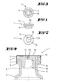
- the sealing plug 1 shown in FIG. 1 and the 10 and 11 seals 38, 39 shown and the protective cap 2 shown in FIG. 7 are in the Plastic injection molding process.
- thermoplastic elastomer plastic is used in rubber-like elasticity and still sufficient Inherent rigidity.
- the sealing plug 1 can be protected from inhalation assign a bottle 3. It is pharmaceutical Applicable bottle 3, such as an infusion bottle.
- the bottle 3 shown in FIG. 4 shows the stopper 1 associated with the neck 4 of the bottle 3, secured by a metallic crimp cap 5.
- the latter also accommodates an inner cap 6.
- the crimp cap 5, which can be referred to as the outer cap is rolled around a collar 7 of the bottle neck 4.
- the flaring point bears the reference number 8.
- the bottle 3 is made of glass, for example.
- the sealing plug 1 is realized as a hollow plug. It sits in an essentially cylindrical seal Mouth 10 of the neck 4.
- the bottle interior opening hollow of the hollow plug 9 carries the Reference number 11.
- the sealing plug 1 is a pierceable sealing body realized. To do this, essentially centrally located piercing area 12 of the sealing plug 1 exposed. Relevant details result from the unpublished German patent application 100 05 833. The disclosure content this registration is included here in full included, also for the purpose of features related to taken application in claims of this application to record with.
- the piercing area 12 is provided by a plug cover 13, which continues in a stopper collar 14 on the bottle side.
- the plug cover 13 has a central area, the piercing area 12, of smaller wall thickness x and an edge area 15 of greater wall thickness y.
- the ratio of X: Y is 3: 4 and in Fig. 5 more likely to be 2: 3 and is based on a somewhat lower, central material accumulation which favors the puncture behavior.
- the plug collar at least in its root area to the plug cover 13 has a greater wall thickness z than the plug cover 13 in its central area, i.e. piercing area 12th
- the protective cap 2 shown in FIGS. 7 and 8 for Syringes in the medical field are walled designed taking other priorities into account.
- the long, cylindrical body on the outside has a cap hat 18 larger material accumulation on which cap hat lengthways into a thin-walled Cap neck 19 continues.
- the protective surrounding the cannula Wall of the cap neck 19 is stepped on the inside cupped; the corresponding cavity 20 goes into one narrowest zone 21, designed as a penetration zone for Protection and locking of the end of the needle body there.
- the neck end has the smallest wall thickness.
- In the area of the jacket wall essentially has this area cylindrically held molding a bulky Ring collar 22.
- the injection point is at an exposed point on the cap hat 18, namely at the top of the cap hat.
- the right thick-walled ceiling is rounded flat convex.
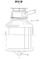
- FIG. 9 shows a transfusion bottle 40, which has an eyelet 41 on its bottom for falling Arrangement of the transfusion bottle 40.
- the bottle head 42 then points down.
- the bottle body is made of plastic, for example PE in penetrable wall thickness. Until the penetration using cannulas or spikes, for example.
- This closure wall of bottle 40 is not shown in detail.
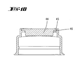
- a cap 43 is placed over the closure wall, as is shown in detail in different embodiments in FIGS. 10 and 11.
- a molded part 44 which represents a seal, is arranged inside the cap 43.
- the seal is pierceable and is located in front of the closure wall of the bottle 40, not shown.
- the seal 44 has a circumferential flange 45 which rests on an associated flange 46 of the cap 43.
- the flange 45 has a significantly smaller wall thickness than a central area of the seal 44.
- the thickness reduced are. Starting from the top and bottom, back-to-back, hemispherical troughs 48 formed. The troughs 48 lead in the area of their largest vertical extension means that the thickness of the Seal 44 to about 1/5 of its greatest thickness is reduced.
- grooves 49 is provided, on the other hand where the edge region 50 in turn has a vertical extension like that of the Middle area of the seal 44, in which preferably an outer surface is also the injection point.
- the moldings in the form of the sealing plug 1, the Protective cap 2 and the seals 44 are not only each produced by plastic injection molding, but also using the same material.
- a thermoplastic elastomer TPE
- the material contains an admixture of mineral Filler.
- the filler content in this regard is 30% or more. It is used as a filler preferably magnesium silicate.
- the mineral Filler has certain flow retardant properties, so that there is a flow cohesion when filling of the mold cavity 23 of the injection molding device 17 comes.
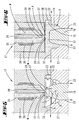
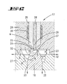
- 5 and 6 are the injection molding Special features, primarily using the example of a sealing plug, explains:
- the injection point A (see, for example, FIGS. 6 and 13) of the hot runner injection is to the injection molding (cf. e.g. 2, 4, 7, 8, 14) 24. He can at the Protective cap 2 is in the center and lies on the sealing plug 1, as is also preferred for the seals 44 central. This achieves an even distribution at high flow rate. Aesthetic flaws do not occur. Even optical irregularities how color deviations are eliminated. In addition, in common injection molds are worked. It is the cavity filling largely independent of temperature. It can be between 200 and 280 ° C without becoming larger would show differences in quality.
- the central access of the injection molding compound M takes place via a nozzle 25 of a molded upper part 26.
- the associated bottom part is at 27 designated.
- the mold cavity 23 is distributed proportionately. in the Center of the lower mold part 27 is a vertical movable form projection, provided by the ejector 16th
- the filling level is controlled by the valve. For this there is a vertically movable in the upper mold part 26 Needle 28. Its needle head 29 finally enters the Mouth of the nozzle 25 (see FIG. 5).
- the stamp-like needle head 29 of the hot runner injection A has a flat end face 30.
- the The front surface extends when closed Hot runner gating A at the same level in the molding wall co-forming, surrounding the mouth of the nozzle 25 Nozzle wall 31.
- the molding wall can Top of the plug cover 13 of the sealing plug 1 be or the corresponding surface of the cap hat 18 of the protective cap 2 or the seal 38 or 39 10 and 11.
- FIGS. 5 and 6 it can be seen that between upper mold part 26 and lower mold part 27 horizontal joint exists, forming a first air discharge 32 with penetrating spray material, the injection molding compound Times.
- a second air outlet 33 exists in the vertical direction, in the form of a ring joint between the ejector 16 and a form-fitting receptacle of the lower mold part 27 for this. This is a complete filling of the mold cavity 23 in the scheduled time without touching the molding markings on the outside such as flow streaks or the like arise. That from the nozzle 25 under pressure outgoing material is through no sack opening non-ventilated.
- thermoplastic Elastomer plastic also plasticizer added.
- the needle 28 standing centrally in the spray channel 35 is surrounded by a heating element 36 on the channel wall side.
- the nozzle wall 31 of the upper mold part 26 points in the case of the plug 1 or a seal 44 a Ring groove 37 on.
- the ring groove is concentric to the Nozzle 25 is triangular in cross section and forms on the Top of the plug cover 13 as it were a target ring 38 off for the correct placement of the cannula or one Spikes.
- the Needle tip also cylindrical and in detail initially then be designed with a spherical end face, the cylindrical area being 0.05 mm, for example and the spherical end face area a further 0.3 mm in the interior of the molding may be offset. Nevertheless but it remains the smooth, also pull-free Detachment. Usual draft angles on the molding are taken into account.
- FIG. 13 shows a representation according to FIG. 6, at which the injection point A of the molding, here the plug 13, opposite the surrounding Molded wall offset to the outside is.
- the needle head 29 can be seen here in the closed state with respect to the surrounding nozzle 25 so far withdrawn that a within the nozzle 25 remaining cylindrical approach of the molding 13 results.
- the injection point 24 compared to the surrounding Molded wall offset to the outside is, according to a technical design 13.
- the surrounding cap 44 including one, here as Web 51 trained cap part have been injected, that covers the injection point 24.
Landscapes
- Engineering & Computer Science (AREA)
- Mechanical Engineering (AREA)
- Manufacturing & Machinery (AREA)
- Chemical & Material Sciences (AREA)
- Dispersion Chemistry (AREA)
- Medical Preparation Storing Or Oral Administration Devices (AREA)
- Injection Moulding Of Plastics Or The Like (AREA)
- Closures For Containers (AREA)
- Moulds For Moulding Plastics Or The Like (AREA)
Abstract
Description
- Fig. 1
- einen im Kunststoff-Spritzverfahren hergestellten Verschlussstopfen in Seitenansicht, das erste Ausführungsbeispiel darstellend;
- Fig. 2
- die Draufsicht hierzu;
- Fig. 3
- die Unteransicht;
- Fig. 4
- einen Vertikalschnitt durch eine Infusionsflasche mit zugeordnetem Verschlussstopfen, unter Aufbringen einer Bördelkappe gesichert;
- Fig. 5
- einen Schnitt durch den Formnestbereich einer Spritzgießvorrichtung, unverfüllt;
- Fig. 6
- eine gleiche Darstellung, jedoch bei verfülltem Formnest;
- Fig. 7
- eine im Kunststoff-Spritzverfahren erzeugte Schutzkappe für eine Spritze, in Seitenansicht;
- Fig. 8
- einen Vertikalschnitt durch die Schutzkappe, stark vergrößert, zusammen das zweite Ausführungsbeispiel verkörpernd;
- Fig. 9
- in Seitenansicht einen dichtungsverschlossenen Behälter, wie er als Infusionsflasche Verwendung findet;
- Fig. 10
- einen Querschnitt durch den Gegenstand gemäß Fig. 9, im Bereich der Verschlussvorrichtung, in einer ersten Ausführungsform;
- Fig. 11
- eine Darstellung gemäß Fig. 10 einer zweiten Ausführungsform;
- Fig. 12
- eine vergrößerte Querschnittsdarstellung des Anspritzbereiches bei bezüglich umgebender Spritzlingswandung in das Innere versetztem Nadelkopf;
- Fig. 13
- eine Darstellung gemäß Fig. 6, jedoch mit gegenüber der umgebenden Spritzlingswandung nach außen versetztem Anspritzpunkt; und
- Fig. 14
- eine Darstellung des Gegenstandes gemäß Fig. 11, wobei der Anspritzpunkt des Elastomerkunststoff-Teilbereiches gegenüber der umgebenden Spritzlingswandung erhaben ist und zugleich in einem weiteren Teilbereich des Spritzlings aufgenommen ist.
Die Bördelstelle trägt das Bezugszeichen 8.
Das Verhältnis von X : Y liegt bei 3 : 4 und in Fig. 5 eher bei 2 : 3 und stellt auf eine etwas geringere, zentrale Materialanhäufung ab, die das Durchstechverhalten begünstigt.
Der Flansch 45 hat eine deutlich geringere Wandstärke als ein mittlerer Bereich der Dichtung 44.
Claims (31)
- Für pharmazeutische Anwendungen dienender Spritzling wie Verschlussstopfen (1) für pharmazeutische Flaschen, Schutzkappe (2) für medizinische Spritzen oder Dichtungselement (38, 39) für pharmazeutische Behälter, wobei der Spritzling (1, 2, 38, 39, 44) zumindest in einem Teilbereich aus einem thermoplastischen Elastomerkunststoff mit einem mineralischen Füllstoffanteil von 30 % oder mehr besteht und dieser Teilbereich einen Heißkanal-Anspritzpunkt aufweist, der als glattflächiger Abdruck gebildet ist.
- Für pharmazeutische Anwendungen dienender Spritzling wie Verschlussstopfen (1) für pharmazeutische Flaschen, Schutzkappe (2) für medizinische Spritzen oder Dichtungselement (38, 39) für pharmazeutische Behälter, wobei der Spritzling (1, 2, 38, 39, 44) in einem Teilbereich aus einem thermoplastischen Elastomerkunststoff mit einem mineralischen Füllstoffanteil von 30 % oder mehr besteht und dieser Teilbereich einen Anspritzpunkt aufweist, der von einem zweiten Teil des Spritzlings, bestehend aus einem anderen Kunststoff, überspritzt ist.
- Spritzling nach Anspruch 2 oder insbesondere danach, dadurch gekennzeichnet, dass der Anspritzpunkt des aus dem elastischen Elastomerkunststoff gebildeten Teilbereich als Heißkanal-Anspritzpunkt gebildet ist.
- Spritzling nach Anspruch 3 oder insbesondere danach, dadurch gekennzeichnet, dass der Heißkanal-Anspritzpunkt als glattflächiger Abdruck gebildet ist.
- Spritzling nach Anspruch 1 oder insbesondere danach, dadurch gekennzeichnet, dass der Spritzling insgesamt aus dem Elastomerkunststoff besteht.
- Spritzling nach einem oder mehreren der vorhergehenden Ansprüche oder insbesondere danach, dadurch gekennzeichnet, dass der Heißkanal-Anspritzpunkt ohne Versetzung nach außen in die umgebende Spritzlingswandung übergeht.
- Spritzling nach einem oder mehreren der vorhergehenden Ansprüche oder insbesondere danach, dadurch gekennzeichnet, dass ein bzgl. der umgebenden Spritzlingswandung nach außen versetzter Heißkanal-Anspritzpunkt von einem Kunststoffteil überfangen ist.
- Spritzling nach einem oder mehreren der vorhergehenden Ansprüche oder insbesondere danach, dass der glattflächige Abdruck des Heißkanal -Anspritzpunktes ebenengleich in die ihn umgebende Spritzlingswandung übergeht.
- Spritzling nach einem oder mehreren der vorhergehenden Ansprüche oder insbesondere danach, dadurch gekennzeichnet, dass der Spritzling überwiegend dickwandig ausgebildet ist.
- Spritzling nach einem oder mehreren der vorhergehenden Ansprüche oder insbesondere danach, dadurch gekennzeichnet, dass im Falle des Verschlussstopfens (1) eine Stopfendecke (13) und ein Stopfenkragen (14) ausgebildet ist und dass eine zentrale Heißkanal-Anspritzung (A) im Bereich der Stopfendecke (13) gegeben ist.
- Spritzling nach einem oder mehreren der vorhergehenden Ansprüche oder insbesondere danach, dadurch gekennzeichnet, dass im Falle des Verschlussstopfens die Stopfendecke (13) einen zentralen Bereich (12) geringerer Wandstärke (x) und einen Randbereich (15) größerer Wandstärke (y) aufweist.
- Spritzling nach einem oder mehreren der vorhergehenden Ansprüche oder insbesondere danach, dadurch gekennzeichnet, dass eine Ausbildung als Schutzkappe (2) für medizinische Spritzen gegeben ist und dass die Schutzkappe (2) eine Heißkanal-Anspritzung (A) im Bereich des Kappenhutes (18) aufweist.
- Spritzling nach einem oder mehreren der vorhergehenden Ansprüche oder insbesondere danach, dadurch gekennzeichnet, dass der thermoplastische Elastomerkunststoff einen Anteil an Weichmachern enthält.
- Spritzling nach einem oder mehreren der vorhergehenden Ansprüche oder insbesondere danach, gekennzeichnet durch eine Ausbildung als Dichtungselement für eine pharmazeutische Flasche, wobei eine zentrale Heißkanal-Anspritzung (A) in einer Außenfläche vorgesehen ist.
- Spritzling nach einem oder mehreren der vorhergehenden Ansprüche oder insbesondere danach, dadurch gekennzeichnet, dass im Falle eines Verschlussstopfens der Stopfenkragen (14) eine größere Wandstärke (z) aufweist als die Stopfendecke (13) in ihrem zentralen Bereich.
- Im Kunststoff-Spritzverfahren hergestellte Schutzkappe (2) für medizinische Spritzen, mit massivem Kappenhut (18) und einem demgegenüber dünnwandigen Kappenhals (19), dadurch gekennzeichnet, dass die Schutzkappe (2) aus thermoplastischem Elastomerkunststoff besteht mit einem mineralischen Füllstoffanteil von 30 % oder mehr und dass eine Heißkanal-Anspritzung (A) im Bereich des Kappenhuts (18) gegeben ist.
- Schutzkappe nach Anspruch 16 oder insbesondere danach, dadurch gekennzeichnet, dass der thermoplastische Elastomerkunststoff einen Anteil an Weichmacher enthält.
- Schutzkappe nach Anspruch 16 oder 17 oder insbesondere danach, dadurch gekennzeichnet, dass eine zentrale Heißkanal-Anspritzung (A) im Bereich der Kappenhut-Spitze vorgenommen ist.
- Verfahren zur Herstellung eines Spritzlings für eine pharmazeutische Anwendung, wie einen Verschlussstopfen (1) für pharmazeutische Flaschen, eine Schutzkappe (2) für medizinische Spritzen oder ein Dichtungselement (38, 39) für pharmazeutische Behältnisse, dadurch gekennzeichnet, dass der Spritzling zumindest in einem Teilbereich aus einem thermoplastischen Elastomerkunststoff mit einem mineralischen Füllstoffanteil von 30 % oder mehr hergestellt wird und dieser Teilbereich mit einer Heißkanal-Anspritzung ausgeführt wird, wobei der Anspritzpunkt als glattflächiger Abdruck ausgebildet wird.
- Verfahren zur Herstellung eines Spritzlings für eine pharmazeutische Anwendung, wie einen Verschlussstopfen (1) für pharmazeutische Flaschen, eine Schutzkappe (2) für medizinische Spritzen oder ein Dichtungselement (38, 39) für pharmazeutische Behältnisse, dadurch gekennzeichnet, dass der Spritzling in einem Teilbereich aus einem thermoplastischen Elastomerkunststoff mit einem mineralischen Füllstoffanteil von 30 % oder mehr hergestellt wird und dieser Teilbereich mit einer einem Anspritzpunkt aufweisenden Anspritzung ausgeführt wird, welcher Anspritzpunkt mit einem einen zweiten Teilbereich des Spritzlings bildenden anderen Kunststoff überspritzt wird.
- Verfahren nach Anspruch 20 oder insbesondere danach, dadurch gekennzeichnet, dass die Verspritzung des thermoplastischen Elastomerkunststoffs mit einer Heißkanal-Anspritzung durchgeführt wird.
- Verfahren nach Anspruch 21 oder insbesondere danach, dadurch gekennzeichnet, dass der Anspritzpunkt der Heißkanal-Anspritzung als glattflächiger Abdruck ausgebildet ist.
- Verfahren nach Anspruch 19 oder insbesondere danach, dadurch gekennzeichnet, dass der Spritzling insgesamt aus dem Elastomerkunststoff hergestellt wird.
- Verfahren nach einem oder mehreren der vorhergehenden Ansprüche oder insbesondere danach, dadurch gekennzeichnet, dass der Heißkanalanspritzpunkt ohne Versetzung nach außen in die umgebende Spritzlingswandung übergehend hergestellt wird.
- Verfahren nach einem oder mehreren der vorhergehenden Ansprüche oder insbesondere danach, dadurch gekennzeichnet, dass der Anspritzpunkt unter Versetzung nach außen gegenüber der umgebenden Spritzlingswandung hergestellt wird.
- Verfahren zur Herstellung eines Verschlussstopfens (1) für pharmazeutische Flaschen (3), wie bspw. Infusionsflaschen im Kunststoff-Spritzverfahren, mit einer Stopfendecke (13) und einem Stopf enkragen (14), dadurch gekennzeichnet, dass ein thermoplastischer Elastomerkunststoff verwendet wird, dem ein mineralischer Füllstoffanteil von 30 % oder mehr beigemischt ist und dass eine zentrale Heißkanal-Anspritzung (A) im Bereich der Stopfendecke (13) des überwiegend dickwandig ausgebildeten Verschlussstopfens (1) vorgenommen wird.
- Verfahren nach Anspruch 26 oder insbesondere danach, dadurch gekennzeichnet, dass der Stopfenkragen (14) mit einer größeren Wandstärke (z) ausgebildet wird als die Stopfendecke (13) in ihren zentralen Bereich.
- Verfahren nach einem der Ansprüche 26 oder 27 oder insbesondere danach, dadurch gekennzeichnet, dass die Stopfendecke (13) mit einem zentralen Bereich geringerer Wandstärke (x) und einem Randbereich (15) größerer Wandstärke (y) ausgebildet wird.
- Verfahren zur Herstellung einer Schutzkappe (2) für medizinische Spritzen im Kunststoff-Spritzverfahren, mit massivem Kappenhut (18) und einem demgegenüber dünnwandigen Kappenhals (19), dadurch gekennzeichnet, dass ein thermoplastischer Elastomerkunststoff verwendet wird, dem ein mineralischer Füllstoffanteil von 30 % oder mehr beigemischt wird und dass eine zentrale Heißkanal-Anspritzung (A) im Bereich des Kappenhuts (18) vorgenommen wird.
- Verfahren nach Anspruch 29 oder insbesondere danach, dadurch gekennzeichnet, dass die Heißkanal-Anspritzung (A) zentral am Kappenhut (18) vorgenommen wird.
- Verfahren nach einem der Ansprüche 29 oder 30 oder insbesondere danach, dadurch gekennzeichnet, dass dem thermoplastischen Elastomerkunststoff ein Anteil an Weichmacher beigegeben wird.
Applications Claiming Priority (5)
| Application Number | Priority Date | Filing Date | Title |
|---|---|---|---|
| DE2000116961 DE10016961C1 (de) | 2000-04-06 | 2000-04-06 | Im Kunststoff-Spritzverfahren hergestellter Verschlussstopfen und Verfahren zur Herstellung eines Verschlussstopfens |
| DE10016961 | 2000-04-06 | ||
| DE10111550 | 2001-03-10 | ||
| DE10111550 | 2001-03-10 | ||
| EP01923713A EP1192092B1 (de) | 2000-04-06 | 2001-04-05 | Verfahren zur Herstellung eines Spritzlings für pharmazeutische Anwendungen |
Related Parent Applications (1)
| Application Number | Title | Priority Date | Filing Date |
|---|---|---|---|
| EP01923713A Division EP1192092B1 (de) | 2000-04-06 | 2001-04-05 | Verfahren zur Herstellung eines Spritzlings für pharmazeutische Anwendungen |
Publications (2)
| Publication Number | Publication Date |
|---|---|
| EP1400458A1 true EP1400458A1 (de) | 2004-03-24 |
| EP1400458B1 EP1400458B1 (de) | 2006-11-22 |
Family
ID=26005198
Family Applications (2)
| Application Number | Title | Priority Date | Filing Date |
|---|---|---|---|
| EP03018445A Expired - Lifetime EP1400458B1 (de) | 2000-04-06 | 2001-04-05 | Für pharmazeutische Anwendungen dienender Spritzling |
| EP01923713A Expired - Lifetime EP1192092B1 (de) | 2000-04-06 | 2001-04-05 | Verfahren zur Herstellung eines Spritzlings für pharmazeutische Anwendungen |
Family Applications After (1)
| Application Number | Title | Priority Date | Filing Date |
|---|---|---|---|
| EP01923713A Expired - Lifetime EP1192092B1 (de) | 2000-04-06 | 2001-04-05 | Verfahren zur Herstellung eines Spritzlings für pharmazeutische Anwendungen |
Country Status (7)
| Country | Link |
|---|---|
| US (1) | US20020113033A1 (de) |
| EP (2) | EP1400458B1 (de) |
| JP (1) | JP2003530253A (de) |
| CN (1) | CN1216773C (de) |
| AU (1) | AU5041501A (de) |
| DE (3) | DE50111509D1 (de) |
| WO (1) | WO2001076967A1 (de) |
Families Citing this family (15)
| Publication number | Priority date | Publication date | Assignee | Title |
|---|---|---|---|---|
| DE10311154A1 (de) | 2003-03-14 | 2004-09-23 | Helvoet Pharma Belgium N.V. | Für pharmazeutische Verwendung dienende Überkappe mit Verschlussstopfen |
| AT500525A1 (de) * | 2003-04-17 | 2006-01-15 | Greiner Bio One Gmbh | Aufnahmevorrichtung sowie aus einer dichtungsvorrichtung und kappe gebildete verschlussvorrichtung |
| US20060036231A1 (en) * | 2004-05-27 | 2006-02-16 | Conard William A | Injection port and method of making the same |
| AU2005203743B1 (en) * | 2005-01-21 | 2006-02-02 | Jody Horan | A Plug for a Hydraulic Fitting |
| GB2423994B (en) * | 2005-03-04 | 2008-07-30 | Bespak Plc | Seal for a dispensing apparatus |
| US8631953B2 (en) * | 2005-08-10 | 2014-01-21 | Abbott Laboratories | Closure for container for holding biological samples |
| FR2893922B1 (fr) * | 2005-11-30 | 2010-05-14 | Biocorp Rech Et Dev | Dispositif de bouchage pour un recipient et recipient equipe d'un tel dispositif |
| US20090166311A1 (en) * | 2007-12-27 | 2009-07-02 | Helvoet Pharma Belgium N.V. | Pharmaceutical closure with a laser-applied marking |
| FR2927316B1 (fr) * | 2008-02-11 | 2010-05-14 | Biocorp Rech Et Dev | Dispositif de bouchage a chapeau d'appui et recipient equipe d'un tel dispositif |
| DE102011050983A1 (de) | 2010-09-09 | 2012-03-15 | Helvoet Pharma Belgium N.V. | Verschlussstopfen für pharmazeutische Anwendungen |
| CN102225611B (zh) * | 2011-04-01 | 2013-05-29 | 宁波天龙电子股份有限公司 | 一次开模两个方向抽芯机构 |
| US10456786B2 (en) | 2013-03-12 | 2019-10-29 | Abbott Laboratories | Septums and related methods |
| DE102017000048A1 (de) * | 2017-01-05 | 2018-07-05 | Kocher-Plastik Maschinenbau Gmbh | Behälter |
| JP7016519B2 (ja) * | 2017-11-20 | 2022-02-07 | 内外化成株式会社 | 医療用キャップ及びその製造方法 |
| MX2023009647A (es) * | 2021-02-19 | 2023-08-24 | Braunform Gmbh | Tapa para cerrar un recipiente para administrar un medicamento y metodo para producirlo. |
Citations (8)
| Publication number | Priority date | Publication date | Assignee | Title |
|---|---|---|---|---|
| US4306852A (en) * | 1979-05-07 | 1981-12-22 | Nipki Po Technologia Na Materialite | Sprueless plastic material injection molding injection apparatus |
| WO1994015850A1 (en) * | 1992-12-30 | 1994-07-21 | Abbott Laboratories | Thin diaphragm stopper for blunt entry device |
| DE4309738C1 (de) * | 1993-03-25 | 1994-10-13 | Pohl Gmbh & Co Kg | Verschlußkappe |
| WO1997029151A1 (en) * | 1996-02-05 | 1997-08-14 | The West Company(Uk) Limited | Composition |
| US5678713A (en) * | 1995-01-10 | 1997-10-21 | Pohl Gmbh & Co. Kg | Arrangement on infusion bottles or the like |
| EP0834457A1 (de) * | 1996-09-27 | 1998-04-08 | Becton Dickinson France S.A. | Verschlusssystem für einen pharmazeutischen Behälter zur Verwendung in einem Gefriertrocknungsverfahren |
| WO1998036986A1 (en) * | 1997-02-20 | 1998-08-27 | Pharmacia & Upjohn Ab | Method of manufacturing pharmaceutical articles |
| EP0873841A2 (de) * | 1997-04-25 | 1998-10-28 | Mold-Masters Limited | Spritzgiessdüse mit einteiligem Einspritzöffnungseinsatz zum Halten eines zylindrischen Ventils |
Family Cites Families (12)
| Publication number | Priority date | Publication date | Assignee | Title |
|---|---|---|---|---|
| JPS549119B1 (de) * | 1970-09-16 | 1979-04-21 | ||
| DE2653993C3 (de) * | 1976-11-27 | 1980-05-14 | Stella-Kg Werner Deussen, 6229 Walluf | Behälter mit abbrechbarem Verschluß |
| DE2723071A1 (de) * | 1977-05-21 | 1978-11-30 | Linde Ag | Spritzgiessverfahren |
| US4363849A (en) * | 1980-10-30 | 1982-12-14 | The Coca-Cola Company | Foamed thermoplastic resin cork having a natural cork-like appearance and a method of injection molding the cork |
| JPS5858057A (ja) * | 1981-10-02 | 1983-04-06 | テルモ株式会社 | 医療容器用栓体 |
| JP2689398B2 (ja) * | 1990-08-24 | 1997-12-10 | 株式会社 大協精工 | ゴム組成物及び医薬品・医療用具用ゴム製品 |
| DE19620196A1 (de) | 1996-05-20 | 1997-11-27 | Audi Ag | Verfahren zum Umformen eines flächigen Metallwerkstückes |
| US5845797A (en) * | 1996-07-31 | 1998-12-08 | Daikyo Seiko, Ltd. | Rubber plug for drug vessel |
| US6085923A (en) * | 1996-08-13 | 2000-07-11 | Neocork Technologies, Inc. | Composite synthetic stopper |
| JP3142521B2 (ja) * | 1998-11-04 | 2001-03-07 | 大成プラス株式会社 | 針刺し止栓とその製造方法 |
| DE10005833A1 (de) | 1999-11-13 | 2001-05-17 | Pohl Gmbh | Verschluß für Infusionsflaschen oder dergleichen |
| US20030030186A1 (en) * | 2000-05-01 | 2003-02-13 | Riiska Matthew T. | Sprueless hydrostatic injection molding |
-
2001
- 2001-04-05 EP EP03018445A patent/EP1400458B1/de not_active Expired - Lifetime
- 2001-04-05 WO PCT/EP2001/003891 patent/WO2001076967A1/de not_active Ceased
- 2001-04-05 DE DE50111509T patent/DE50111509D1/de not_active Expired - Lifetime
- 2001-04-05 AU AU50415/01A patent/AU5041501A/en not_active Abandoned
- 2001-04-05 CN CN018008399A patent/CN1216773C/zh not_active Expired - Fee Related
- 2001-04-05 EP EP01923713A patent/EP1192092B1/de not_active Expired - Lifetime
- 2001-04-05 US US09/980,227 patent/US20020113033A1/en not_active Abandoned
- 2001-04-05 DE DE50103605T patent/DE50103605D1/de not_active Expired - Fee Related
- 2001-04-05 JP JP2001574454A patent/JP2003530253A/ja active Pending
- 2001-04-05 DE DE10117158A patent/DE10117158A1/de not_active Withdrawn
Patent Citations (8)
| Publication number | Priority date | Publication date | Assignee | Title |
|---|---|---|---|---|
| US4306852A (en) * | 1979-05-07 | 1981-12-22 | Nipki Po Technologia Na Materialite | Sprueless plastic material injection molding injection apparatus |
| WO1994015850A1 (en) * | 1992-12-30 | 1994-07-21 | Abbott Laboratories | Thin diaphragm stopper for blunt entry device |
| DE4309738C1 (de) * | 1993-03-25 | 1994-10-13 | Pohl Gmbh & Co Kg | Verschlußkappe |
| US5678713A (en) * | 1995-01-10 | 1997-10-21 | Pohl Gmbh & Co. Kg | Arrangement on infusion bottles or the like |
| WO1997029151A1 (en) * | 1996-02-05 | 1997-08-14 | The West Company(Uk) Limited | Composition |
| EP0834457A1 (de) * | 1996-09-27 | 1998-04-08 | Becton Dickinson France S.A. | Verschlusssystem für einen pharmazeutischen Behälter zur Verwendung in einem Gefriertrocknungsverfahren |
| WO1998036986A1 (en) * | 1997-02-20 | 1998-08-27 | Pharmacia & Upjohn Ab | Method of manufacturing pharmaceutical articles |
| EP0873841A2 (de) * | 1997-04-25 | 1998-10-28 | Mold-Masters Limited | Spritzgiessdüse mit einteiligem Einspritzöffnungseinsatz zum Halten eines zylindrischen Ventils |
Also Published As
| Publication number | Publication date |
|---|---|
| CN1366505A (zh) | 2002-08-28 |
| EP1192092A1 (de) | 2002-04-03 |
| CN1216773C (zh) | 2005-08-31 |
| WO2001076967A1 (de) | 2001-10-18 |
| DE50111509D1 (de) | 2007-01-04 |
| EP1192092B1 (de) | 2004-09-15 |
| EP1400458B1 (de) | 2006-11-22 |
| US20020113033A1 (en) | 2002-08-22 |
| AU5041501A (en) | 2001-10-23 |
| JP2003530253A (ja) | 2003-10-14 |
| DE10117158A1 (de) | 2001-11-15 |
| DE50103605D1 (de) | 2004-10-21 |
Similar Documents
| Publication | Publication Date | Title |
|---|---|---|
| EP1400458A1 (de) | Für pharmazeutische Anwendungen dienender Spritzling sowie Verfahren zur Herstellung des Spritzlings | |
| DE69712954T2 (de) | Zum Zeitpunkt der Entsorgung von einer Flasche trennbare Scharnierkappe | |
| EP0364783B1 (de) | Verschluss für eine Medikamentenflasche und Verfahren zur Herstellung dieses Verschlusses | |
| DE60108268T2 (de) | Düse für spritzgiesswerkzeug | |
| EP3661723B1 (de) | Blasform-, füll- und schliessverfahren sowie danach hergestelltes behältererzeugnis, insbesondere ampullenerzeugnis | |
| EP0312725B1 (de) | Tropferflasche und Verfahren zu ihrer Herstellung | |
| EP0786417B1 (de) | Kunststofftube mit einem Tubenkörper, sowie Verfahren zu deren Herstellung | |
| EP0034997B1 (de) | Verschlusskappe für einen Behälter | |
| EP3687474A1 (de) | Behälter sowie verbindungs- und herstellvorrichtung | |
| DE3231859C2 (de) | In einem Arbeitsgang hergestellter, gefüllter und verschlossener, blasgeformter, flaschenförmiger Behälter | |
| EP3151807B1 (de) | Behältnis | |
| DE69006879T2 (de) | Originalitätsverschluss für Behälter. | |
| WO2012116790A1 (de) | Verschluss für eine spritze und herstellungsverfahren | |
| EP2121455B1 (de) | Kunststoff-ampulle | |
| DE3135735A1 (de) | "behaelter" | |
| DE2748186A1 (de) | Abdichteinrichtung | |
| DE69704357T2 (de) | Einteilig mit dem behälter geformter, wiederverwendbarer verschluss und verfahren zu dessen herstellung | |
| CH639042A5 (de) | Behaelterverschlusskappe zur anbringung an einem behaelterhals und verfahren zu ihrer herstellung. | |
| DE2108061C3 (de) | Behälter mit einem Hals, der durch einen dem Hals bei seiner Formung einstückig angeformten durchstoßbaren Deckel verschlossen ist, und Verfahren zu seiner Herstellung | |
| WO1984002694A1 (fr) | Couvercle de recipient et installation pour sa fabrication | |
| DE4404672A1 (de) | Verfahren und Vorrichtung zur Herstellung von Bürsten | |
| DE2509504B2 (de) | Schutzkappe für einen eine zu sterilisierende Lösung enthaltenden Kunststoffbehälter | |
| DE2055986A1 (de) | Erzeugnis insbesondere Behalter, be stehend aus zwei durch eine Schwachungs linie miteinander verbundenen Teilen | |
| DE10016961C1 (de) | Im Kunststoff-Spritzverfahren hergestellter Verschlussstopfen und Verfahren zur Herstellung eines Verschlussstopfens | |
| DE4309654C2 (de) | Ringförmige Dichtung |
Legal Events
| Date | Code | Title | Description |
|---|---|---|---|
| PUAI | Public reference made under article 153(3) epc to a published international application that has entered the european phase |
Free format text: ORIGINAL CODE: 0009012 |
|
| AC | Divisional application: reference to earlier application |
Ref document number: 1192092 Country of ref document: EP Kind code of ref document: P |
|
| AK | Designated contracting states |
Kind code of ref document: A1 Designated state(s): DE FR IT |
|
| 17P | Request for examination filed |
Effective date: 20040827 |
|
| 17Q | First examination report despatched |
Effective date: 20041018 |
|
| AKX | Designation fees paid |
Designated state(s): DE FR IT |
|
| GRAP | Despatch of communication of intention to grant a patent |
Free format text: ORIGINAL CODE: EPIDOSNIGR1 |
|
| RTI1 | Title (correction) |
Free format text: INJECTION MOULDED PART FOR PHARMACEUTICAL USE |
|
| GRAS | Grant fee paid |
Free format text: ORIGINAL CODE: EPIDOSNIGR3 |
|
| GRAA | (expected) grant |
Free format text: ORIGINAL CODE: 0009210 |
|
| AC | Divisional application: reference to earlier application |
Ref document number: 1192092 Country of ref document: EP Kind code of ref document: P |
|
| AK | Designated contracting states |
Kind code of ref document: B1 Designated state(s): DE FR IT |
|
| RIN1 | Information on inventor provided before grant (corrected) |
Inventor name: CLAESSENS, ALBERT, LOUIS, VICTOR, JOZEF |
|
| REF | Corresponds to: |
Ref document number: 50111509 Country of ref document: DE Date of ref document: 20070104 Kind code of ref document: P |
|
| ET | Fr: translation filed | ||
| PLBE | No opposition filed within time limit |
Free format text: ORIGINAL CODE: 0009261 |
|
| STAA | Information on the status of an ep patent application or granted ep patent |
Free format text: STATUS: NO OPPOSITION FILED WITHIN TIME LIMIT |
|
| 26N | No opposition filed |
Effective date: 20070823 |
|
| PGFP | Annual fee paid to national office [announced via postgrant information from national office to epo] |
Ref country code: IT Payment date: 20140423 Year of fee payment: 14 Ref country code: FR Payment date: 20140408 Year of fee payment: 14 Ref country code: DE Payment date: 20140519 Year of fee payment: 14 |
|
| REG | Reference to a national code |
Ref country code: DE Ref legal event code: R119 Ref document number: 50111509 Country of ref document: DE |
|
| PG25 | Lapsed in a contracting state [announced via postgrant information from national office to epo] |
Ref country code: DE Free format text: LAPSE BECAUSE OF NON-PAYMENT OF DUE FEES Effective date: 20151103 Ref country code: IT Free format text: LAPSE BECAUSE OF NON-PAYMENT OF DUE FEES Effective date: 20150405 |
|
| REG | Reference to a national code |
Ref country code: FR Ref legal event code: ST Effective date: 20151231 |
|
| PG25 | Lapsed in a contracting state [announced via postgrant information from national office to epo] |
Ref country code: FR Free format text: LAPSE BECAUSE OF NON-PAYMENT OF DUE FEES Effective date: 20150430 |