EP1400482A1 - Seilwinde mit Übersetzungsanordnung und Bremseinrichtung - Google Patents
Seilwinde mit Übersetzungsanordnung und Bremseinrichtung Download PDFInfo
- Publication number
- EP1400482A1 EP1400482A1 EP02405731A EP02405731A EP1400482A1 EP 1400482 A1 EP1400482 A1 EP 1400482A1 EP 02405731 A EP02405731 A EP 02405731A EP 02405731 A EP02405731 A EP 02405731A EP 1400482 A1 EP1400482 A1 EP 1400482A1
- Authority
- EP
- European Patent Office
- Prior art keywords
- cable winch
- winch
- drive unit
- braking device
- brake
- Prior art date
- Legal status (The legal status is an assumption and is not a legal conclusion. Google has not performed a legal analysis and makes no representation as to the accuracy of the status listed.)
- Granted
Links
- 230000005540 biological transmission Effects 0.000 claims abstract description 6
- 238000011084 recovery Methods 0.000 claims description 3
- 238000012423 maintenance Methods 0.000 description 4
- 230000007547 defect Effects 0.000 description 3
- 238000010276 construction Methods 0.000 description 2
- 239000012530 fluid Substances 0.000 description 2
- 238000000034 method Methods 0.000 description 2
- 238000006243 chemical reaction Methods 0.000 description 1
- 230000002950 deficient Effects 0.000 description 1
- 230000001934 delay Effects 0.000 description 1
- 230000000694 effects Effects 0.000 description 1
- 239000007788 liquid Substances 0.000 description 1
- 238000000926 separation method Methods 0.000 description 1
- 230000009747 swallowing Effects 0.000 description 1
- 238000004804 winding Methods 0.000 description 1
Images


Classifications
-
- B—PERFORMING OPERATIONS; TRANSPORTING
- B66—HOISTING; LIFTING; HAULING
- B66D—CAPSTANS; WINCHES; TACKLES, e.g. PULLEY BLOCKS; HOISTS
- B66D1/00—Rope, cable, or chain winding mechanisms; Capstans
- B66D1/02—Driving gear
- B66D1/14—Power transmissions between power sources and drums or barrels
-
- B—PERFORMING OPERATIONS; TRANSPORTING
- B66—HOISTING; LIFTING; HAULING
- B66D—CAPSTANS; WINCHES; TACKLES, e.g. PULLEY BLOCKS; HOISTS
- B66D5/00—Braking or detent devices characterised by application to lifting or hoisting gear, e.g. for controlling the lowering of loads
- B66D5/02—Crane, lift hoist, or winch brakes operating on drums, barrels, or ropes
- B66D5/12—Crane, lift hoist, or winch brakes operating on drums, barrels, or ropes with axial effect
- B66D5/14—Crane, lift hoist, or winch brakes operating on drums, barrels, or ropes with axial effect embodying discs
Definitions
- the invention relates to a cable winch comprising a translation arrangement and at least one drive unit.
- Cable winches are used in various technical fields, the winches differ depending on the requirements Have dimensions. Especially with winches with large ones Rope lengths result in corresponding dimensions for the Winch, which is a winch handling for example Make transportation or maintenance difficult. For an operation of such large winches must also have a drive unit designed for them to be provided. As a rule, the drive unit a compact, consisting of a few parts Build up, which turns out to be when defects occur proves disadvantageous. The entire drive unit must be repaired be removed, causing the winch not is operational and there are delays in the workflow.
- the object of the present invention is to overcome the disadvantages to avoid the known, especially with a winch to provide an alternative translation arrangement.
- the task is solved by a winch with at least corresponding to a drive unit and a translation arrangement the characteristic features of the independent claims.
- a cable winch comprises a transmission arrangement and at least one drive unit, the translation arrangement a spur gear, and at least two with that Spur gear meshing pinion, and the drive unit is connected to a pinion.
- the winch is characterized by at least one braking device, which is connected to the second pinion.
- the drive unit winds or unwinds the rope on or from the rope drum.
- suitable drive units such as electric motor, hydraulic motor etc. known. Hydraulic motors are preferred, in particular Axial piston motors or motors based on the Gehrotore system, because they have advantageous control properties.
- a braking device both slows down the Rotational movement of the rope drum when the rope is changed Speed should be wound out or wound up as well a determination of the rope drum when the winch is at a standstill.
- the drive unit as well as the braking devices are located according to the invention on the same end face of the rope drum and are also for maintenance or repair accessible.
- the separate arrangement still leaves one quick adjustment of the drive unit or the braking device to changing requirements when operating the winch to. For example, by installing a more powerful engine the rope speed (taking into account the load capacity the winch) can be increased or by a finer controllable motor a more precise positioning of the rope end achieved at more distant load attachment points become.
- a winch can also be replaced a braking device against another one functioning Convert braking device more easily.
- Disc brakes or multi-disc brakes can be used as the braking device deploy.
- the number of braking devices judges according to the requirements placed on the winch become. For security reasons, however, it is advantageous provide redundancy of the braking device. That is why the braking device has at least one disc brake or multi-disc brake exhibit.
- a braking device is preferred can be selected, the two disc or multi-disc brakes having.
- the braking device is further preferably designed if they have two or more differently acting brakes having.
- the braking device can have two disc brakes and two multi-disc brakes. While one of these brake types can act as a service brake the other type can be used as a parking brake.
- the Those skilled in the art are familiar with other types of brakes, which are also known can be used as a braking device in the sense of the invention.
- the spur gear is in a bearing arrangement with a variety stored by engine positions. Leave depending on the application different drive units and brake arrangements combine into one unit.
- the cable winch is preferably designed such that the transmission arrangement can be flanged to the cable drum. Since the Translation arrangement not fixed, i.e. not inseparable from the Rope drum or with the shaft on which the rope drum is arranged is connected, maintenance or Repairing the winch made easier. In the event of a defect can separate the translation arrangement from the cable drum are replaced by a replacement translation arrangement become. The cable winch can continue to be operated and the defective translation arrangement of a workshop for repair are fed. Different types of flanging are known to the expert.
- a cable winch according to the invention is further preferred with a Disc or band brake equipped as an emergency brake.
- a Disc or band brake equipped as an emergency brake.
- the cable winch is designed that the drive unit is used for energy recovery.
- the drive unit is thus used as a braking device and also leads to a more economical operation of the Winch, in particular, can extend the life of the other Braking devices can be achieved.
- the energy generated when using a hydraulic motor be introduced into another fluid system from where can be retrieved from this energy for further use can.
- Other drive units known to those skilled in the art are also conceivable, which can be used for energy recovery are.
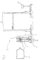
- a translation arrangement 1 with the appropriate positioning the drive units 3 and the braking devices 4 and 7 is shown in Figure 1.
- On the translation order 1 with flange 8 are five hydraulic motors 3 and each two disc brakes 4 and multi-disc brakes 7 are arranged. she also act on the invisible sprockets Spur gear 2, not shown, can be clearly seen in FIG. that the central axes of the motors 3 and brakes 4, 7 lie on a circumferential circle K.
- the translation u between Spur gear 2 and pinions 5 is 15.
- the hydraulic motors 3 are adjustable, which means that different services from the Motors 3 can be transferred to the winch. As engines 3 can axial piston motors with a hydraulic 2-point adjustment and a swallowing volume of 65 cc and one maximum pressure up to 400 bar can be used.
- the multi-disc brakes 7 are executed as hydraulically released spring pressure, multi-disc multi-disc brakes, serve primarily to determine the Rope winch when no rope is being ejected or spooled. As a service brake are due to their better controllability primarily used the disc brakes 4.
- the disc brakes are as hydraulically operated, ventilated disc brakes executed. The at least double arrangement of the braking devices 4 and 7 is based on the principle that in the event of failure one of the brakes is still operational Cable winch exists, albeit with possibly considerable Restriction.
- FIG. 2 shows a cable winch 9 in cross section the shaft 6 are both the translation arrangement 1 and the cable drum 10 and a band brake 11 as an emergency brake arranged.
- the translation arrangement 1 is on the shaft 6 pushed on and fixed there.
- the spur gear is in cross section 2 and a pinion 5 of the translation arrangement 1 can be seen.
- the Hydraulic motor 3, which is shown in a deducted Position shown drives the spur gear 2 via the pinion 5 on.
- the spur gear 2 is supported in the bearing arrangement 13.
- the Hydraulic node 3 is in one of the assembly positions 12 of the bearing arrangement 13.
- the disc brake 4 and its arrangement with respect to the cable winch 9 shows FIG. 3.
- the disc brake 4 has a pinion 5 connected, which in turn engages with the spur gear 2 stands.
- the rest of the arrangement of translation arrangement 1 to the shaft 6 or the cable drum 10 corresponds to the description to figure 2.
Landscapes
- Engineering & Computer Science (AREA)
- Mechanical Engineering (AREA)
- Braking Arrangements (AREA)
Abstract
Description
Eine Seilwinde mit einer Anordnung von Motoren, die auf einen mit einem Zahnkranz versehenen Flansch wirken, beschreibt DE 1920895. Die Seilwinde wird entweder durch direkt auf die Motoren wirkende Bremsen oder durch eine Lamellenbremse, die auf der gegenüberliegenden Trommelseite angeordnet ist, gebremst. Derartige Aufbauweisen sind allerdings nachteilig, da sie eine kompakte Bauweise verhindern bzw. die Wartung der Seilwinde schwierig gestalten.
- Figur 1:
- eine Aufsicht auf die Anordnung von Antriebseinheiten und Bremseinrichtungen;
- Figur 2:
- einen Querschnitt einer Seilwinde mit Antriebseinheit, Übersetzungsanordnung und Seiltrommel; und
- Figur 3:
- einen Querschnitt einer Seilwinde mit Bremseinrichtung, Übersetzungsanordnung und Seiltrommel.
Claims (10)
- Seilwinde (9) umfassend eine Übersetzungsanordnung (1) und mindestens eine Antriebseinheit (3), wobei die Übersetzungsanordnung (1) ein Stirnrad (2) und mindestens zwei mit dem Stirnrad (2) in Eingriff stehende Ritzel (5) aufweist, und wobei die Antriebseinheit (3) mit einem Ritzel (5) verbunden ist, dadurch gekennzeichnet, dass die Seilwinde (9) mindestens eine Bremseinrichtung (4, 7) aufweist, wobei die Bremseinrichtung (4,7) mit dem zweiten Ritzel (5) verbunden ist.
- Seilwinde (9) nach Anspruch 1, dadurch gekennzeichnet, dass die Bremseinrichtung (4, 7) mindestens eine Scheibenbremse (4) umfasst.
- Seilwinde (9) nach Anspruch 1 oder 2, dadurch gekennzeichnet, dass die Bremseinrichtung (4, 7) mindestens eine Lamellenbremse (7) umfasst.
- Seilwinde (9) nach einem der Ansprüche 1 bis 3, dadurch gekennzeichnet, dass die Antriebseinheit (3) ein Hydraulikmotor oder Elektromotor ist.
- Seilwinde (9) nach einem der Ansprüche 1 bis 4, dadurch gekennzeichnet, dass die Antriebseinheiten (3) getrennt voneinander steuerbar sind.
- Seilwinde (9) nach einem der Ansprüche 1 bis 5, dadurch gekennzeichnet, dass die Seilwinde (9) als Notbremse eine Bandbremse (11) oder Scheibenbremse umfasst.
- Seilwinde (9) nach einem der Ansprüche 1 bis 6, dadurch gekennzeichnet, dass die Übersetzungsanordnung (1) an die Seiltrommel (10) anflanschbar ist.
- Seilwinde (9) nach einem der Ansprüche 1 bis 7, dadurch gekennzeichnet, dass die Antriebseinheit (3) zur Energie-Rückgewinnung verwendbar ist.
- Seilwinde (9) nach einem der vorangehenden Ansprüche, dadurch gekennzeichnet, dass das Stirnrad (2) in einer Lageranordnung (13) gelagert ist, welche Lageranordnung (13) mit einer Mehrzahl von Montage-Positionen (12) zum Anbringen von Antriebseinheiten (3) und Bremseinrichtungen (4, 7) versehen ist.
- Seilwinde (9) nach einem der vorangehenden Ansprüche, dadurch gekennzeichnet, dass die Seilwinde (9) wenigstens zwei Antriebseinheiten (3) aufweist.
Priority Applications (3)
| Application Number | Priority Date | Filing Date | Title |
|---|---|---|---|
| AT02405731T ATE292087T1 (de) | 2002-08-28 | 2002-08-28 | Seilwinde mit übersetzungsanordnung und bremseinrichtung |
| EP02405731A EP1400482B1 (de) | 2002-08-28 | 2002-08-28 | Seilwinde mit Übersetzungsanordnung und Bremseinrichtung |
| DE50202638T DE50202638D1 (de) | 2002-08-28 | 2002-08-28 | Seilwinde mit Übersetzungsanordnung und Bremseinrichtung |
Applications Claiming Priority (1)
| Application Number | Priority Date | Filing Date | Title |
|---|---|---|---|
| EP02405731A EP1400482B1 (de) | 2002-08-28 | 2002-08-28 | Seilwinde mit Übersetzungsanordnung und Bremseinrichtung |
Publications (2)
| Publication Number | Publication Date |
|---|---|
| EP1400482A1 true EP1400482A1 (de) | 2004-03-24 |
| EP1400482B1 EP1400482B1 (de) | 2005-03-30 |
Family
ID=31897001
Family Applications (1)
| Application Number | Title | Priority Date | Filing Date |
|---|---|---|---|
| EP02405731A Expired - Lifetime EP1400482B1 (de) | 2002-08-28 | 2002-08-28 | Seilwinde mit Übersetzungsanordnung und Bremseinrichtung |
Country Status (3)
| Country | Link |
|---|---|
| EP (1) | EP1400482B1 (de) |
| AT (1) | ATE292087T1 (de) |
| DE (1) | DE50202638D1 (de) |
Cited By (1)
| Publication number | Priority date | Publication date | Assignee | Title |
|---|---|---|---|---|
| DE102016116322A1 (de) * | 2015-09-04 | 2017-03-09 | Kabushiki Kaisha Kobe Seiko Sho (Kobe Steel, Ltd.) | Bremsvorrichtung für eine elektrische Winde |
Citations (3)
| Publication number | Priority date | Publication date | Assignee | Title |
|---|---|---|---|---|
| US1922303A (en) * | 1930-09-19 | 1933-08-15 | Kinzbach Frank | Load handling apparatus |
| US2525764A (en) * | 1946-05-28 | 1950-10-17 | Sasgen Derrick Co | Safety winch |
| US3726801A (en) * | 1971-03-25 | 1973-04-10 | Kidde & Co Walter | Power winch for cranes and the like |
-
2002
- 2002-08-28 AT AT02405731T patent/ATE292087T1/de not_active IP Right Cessation
- 2002-08-28 EP EP02405731A patent/EP1400482B1/de not_active Expired - Lifetime
- 2002-08-28 DE DE50202638T patent/DE50202638D1/de not_active Expired - Fee Related
Patent Citations (3)
| Publication number | Priority date | Publication date | Assignee | Title |
|---|---|---|---|---|
| US1922303A (en) * | 1930-09-19 | 1933-08-15 | Kinzbach Frank | Load handling apparatus |
| US2525764A (en) * | 1946-05-28 | 1950-10-17 | Sasgen Derrick Co | Safety winch |
| US3726801A (en) * | 1971-03-25 | 1973-04-10 | Kidde & Co Walter | Power winch for cranes and the like |
Cited By (2)
| Publication number | Priority date | Publication date | Assignee | Title |
|---|---|---|---|---|
| DE102016116322A1 (de) * | 2015-09-04 | 2017-03-09 | Kabushiki Kaisha Kobe Seiko Sho (Kobe Steel, Ltd.) | Bremsvorrichtung für eine elektrische Winde |
| DE102016116322B4 (de) * | 2015-09-04 | 2017-10-19 | Kabushiki Kaisha Kobe Seiko Sho (Kobe Steel, Ltd.) | Bremsvorrichtung für eine elektrische Winde |
Also Published As
| Publication number | Publication date |
|---|---|
| ATE292087T1 (de) | 2005-04-15 |
| EP1400482B1 (de) | 2005-03-30 |
| DE50202638D1 (de) | 2005-05-04 |
Similar Documents
| Publication | Publication Date | Title |
|---|---|---|
| DE102015100181B4 (de) | Systemanordnung von Hubwerken und Verfahren zum Betrieb der Systemanordnung | |
| DE2717143A1 (de) | Antriebssystem, insbesondere fuer foerderanlagen | |
| DE102009054294A1 (de) | Elektrische Scheibenbremse | |
| EP2948406A1 (de) | Seilwinde | |
| EP0949743A2 (de) | Elektrische Maschine, insbesondere für Fahrstuhlantrieb | |
| DE60204256T2 (de) | Durch Drehmoment lösbare Scheibenbremse | |
| EP1478826B1 (de) | Hebewerk | |
| DE2837918B1 (de) | Vorrichtung zur Herstellung von Wendeln aus Draht | |
| EP2565144A1 (de) | Seilwinde | |
| WO2005035427A1 (de) | Hebewerk | |
| EP1400482B1 (de) | Seilwinde mit Übersetzungsanordnung und Bremseinrichtung | |
| DE2839723C2 (de) | Lastdrehvorrichtung | |
| DE1936097A1 (de) | Seilwinde | |
| DE102012015614A1 (de) | Mehrfachtrommelfördermaschine | |
| DE19846671A1 (de) | Treibscheibenbremse mit erhöhter Redundanz | |
| DE3135603C2 (de) | ||
| DE10246588B4 (de) | Nothalte-Bremseinrichtung für Aufzugsmaschinen | |
| DE102008030124A1 (de) | Getriebeloses Hebewerk | |
| DE20000913U1 (de) | Getriebehebewerk | |
| EP3491273B1 (de) | Antriebsvorrichtung mit überlagerungsgetriebe | |
| DE19530891A1 (de) | Hebezeug, das mit einem Zugmittel betrieben wird | |
| DE4413854A1 (de) | Verschwenkeinrichtung | |
| DE421660C (de) | Steuermaschine fuer hydraulisch betriebene Plateau-Versenkungen fuer Theaterbuehnen | |
| DE2848469C2 (de) | Mehrfachziehmaschine zum gleitlosen Ziehen von Draht | |
| DE102019133396A1 (de) | Gelenkantrieb mit Planetengetriebe, Großmanipulator und Autobetonpumpe |
Legal Events
| Date | Code | Title | Description |
|---|---|---|---|
| PUAI | Public reference made under article 153(3) epc to a published international application that has entered the european phase |
Free format text: ORIGINAL CODE: 0009012 |
|
| AK | Designated contracting states |
Kind code of ref document: A1 Designated state(s): AT BE BG CH CY CZ DE DK EE ES FI FR GB GR IE IT LI LU MC NL PT SE SK TR |
|
| AX | Request for extension of the european patent |
Extension state: AL LT LV MK RO SI |
|
| 17P | Request for examination filed |
Effective date: 20040519 |
|
| GRAP | Despatch of communication of intention to grant a patent |
Free format text: ORIGINAL CODE: EPIDOSNIGR1 |
|
| AKX | Designation fees paid |
Designated state(s): AT BE BG CH CY CZ DE DK EE ES FI FR GB GR IE IT LI LU MC NL PT SE SK TR |
|
| GRAS | Grant fee paid |
Free format text: ORIGINAL CODE: EPIDOSNIGR3 |
|
| GRAA | (expected) grant |
Free format text: ORIGINAL CODE: 0009210 |
|
| AK | Designated contracting states |
Kind code of ref document: B1 Designated state(s): AT BE BG CH CY CZ DE DK EE ES FI FR GB GR IE IT LI LU MC NL PT SE SK TR |
|
| PG25 | Lapsed in a contracting state [announced via postgrant information from national office to epo] |
Ref country code: IT Free format text: LAPSE BECAUSE OF FAILURE TO SUBMIT A TRANSLATION OF THE DESCRIPTION OR TO PAY THE FEE WITHIN THE PRESCRIBED TIME-LIMIT;WARNING: LAPSES OF ITALIAN PATENTS WITH EFFECTIVE DATE BEFORE 2007 MAY HAVE OCCURRED AT ANY TIME BEFORE 2007. THE CORRECT EFFECTIVE DATE MAY BE DIFFERENT FROM THE ONE RECORDED. Effective date: 20050330 Ref country code: IE Free format text: LAPSE BECAUSE OF FAILURE TO SUBMIT A TRANSLATION OF THE DESCRIPTION OR TO PAY THE FEE WITHIN THE PRESCRIBED TIME-LIMIT Effective date: 20050330 Ref country code: TR Free format text: LAPSE BECAUSE OF FAILURE TO SUBMIT A TRANSLATION OF THE DESCRIPTION OR TO PAY THE FEE WITHIN THE PRESCRIBED TIME-LIMIT Effective date: 20050330 Ref country code: GB Free format text: LAPSE BECAUSE OF FAILURE TO SUBMIT A TRANSLATION OF THE DESCRIPTION OR TO PAY THE FEE WITHIN THE PRESCRIBED TIME-LIMIT Effective date: 20050330 Ref country code: CZ Free format text: LAPSE BECAUSE OF FAILURE TO SUBMIT A TRANSLATION OF THE DESCRIPTION OR TO PAY THE FEE WITHIN THE PRESCRIBED TIME-LIMIT Effective date: 20050330 Ref country code: FI Free format text: LAPSE BECAUSE OF FAILURE TO SUBMIT A TRANSLATION OF THE DESCRIPTION OR TO PAY THE FEE WITHIN THE PRESCRIBED TIME-LIMIT Effective date: 20050330 Ref country code: SK Free format text: LAPSE BECAUSE OF FAILURE TO SUBMIT A TRANSLATION OF THE DESCRIPTION OR TO PAY THE FEE WITHIN THE PRESCRIBED TIME-LIMIT Effective date: 20050330 Ref country code: NL Free format text: LAPSE BECAUSE OF FAILURE TO SUBMIT A TRANSLATION OF THE DESCRIPTION OR TO PAY THE FEE WITHIN THE PRESCRIBED TIME-LIMIT Effective date: 20050330 Ref country code: EE Free format text: LAPSE BECAUSE OF FAILURE TO SUBMIT A TRANSLATION OF THE DESCRIPTION OR TO PAY THE FEE WITHIN THE PRESCRIBED TIME-LIMIT Effective date: 20050330 |
|
| REG | Reference to a national code |
Ref country code: GB Ref legal event code: FG4D Free format text: NOT ENGLISH |
|
| REG | Reference to a national code |
Ref country code: CH Ref legal event code: EP |
|
| REF | Corresponds to: |
Ref document number: 50202638 Country of ref document: DE Date of ref document: 20050504 Kind code of ref document: P |
|
| REG | Reference to a national code |
Ref country code: IE Ref legal event code: FG4D Free format text: LANGUAGE OF EP DOCUMENT: GERMAN |
|
| PG25 | Lapsed in a contracting state [announced via postgrant information from national office to epo] |
Ref country code: BG Free format text: LAPSE BECAUSE OF FAILURE TO SUBMIT A TRANSLATION OF THE DESCRIPTION OR TO PAY THE FEE WITHIN THE PRESCRIBED TIME-LIMIT Effective date: 20050630 Ref country code: DK Free format text: LAPSE BECAUSE OF FAILURE TO SUBMIT A TRANSLATION OF THE DESCRIPTION OR TO PAY THE FEE WITHIN THE PRESCRIBED TIME-LIMIT Effective date: 20050630 Ref country code: GR Free format text: LAPSE BECAUSE OF FAILURE TO SUBMIT A TRANSLATION OF THE DESCRIPTION OR TO PAY THE FEE WITHIN THE PRESCRIBED TIME-LIMIT Effective date: 20050630 |
|
| PG25 | Lapsed in a contracting state [announced via postgrant information from national office to epo] |
Ref country code: ES Free format text: LAPSE BECAUSE OF FAILURE TO SUBMIT A TRANSLATION OF THE DESCRIPTION OR TO PAY THE FEE WITHIN THE PRESCRIBED TIME-LIMIT Effective date: 20050711 |
|
| PGFP | Annual fee paid to national office [announced via postgrant information from national office to epo] |
Ref country code: AT Payment date: 20050811 Year of fee payment: 4 |
|
| PGFP | Annual fee paid to national office [announced via postgrant information from national office to epo] |
Ref country code: DE Payment date: 20050825 Year of fee payment: 4 |
|
| PG25 | Lapsed in a contracting state [announced via postgrant information from national office to epo] |
Ref country code: CY Free format text: LAPSE BECAUSE OF FAILURE TO SUBMIT A TRANSLATION OF THE DESCRIPTION OR TO PAY THE FEE WITHIN THE PRESCRIBED TIME-LIMIT Effective date: 20050828 |
|
| PG25 | Lapsed in a contracting state [announced via postgrant information from national office to epo] |
Ref country code: MC Free format text: LAPSE BECAUSE OF NON-PAYMENT OF DUE FEES Effective date: 20050831 Ref country code: BE Free format text: LAPSE BECAUSE OF NON-PAYMENT OF DUE FEES Effective date: 20050831 Ref country code: LU Free format text: LAPSE BECAUSE OF NON-PAYMENT OF DUE FEES Effective date: 20050831 |
|
| PG25 | Lapsed in a contracting state [announced via postgrant information from national office to epo] |
Ref country code: PT Free format text: LAPSE BECAUSE OF FAILURE TO SUBMIT A TRANSLATION OF THE DESCRIPTION OR TO PAY THE FEE WITHIN THE PRESCRIBED TIME-LIMIT Effective date: 20050908 |
|
| NLV1 | Nl: lapsed or annulled due to failure to fulfill the requirements of art. 29p and 29m of the patents act | ||
| GBV | Gb: ep patent (uk) treated as always having been void in accordance with gb section 77(7)/1977 [no translation filed] |
Effective date: 20050330 |
|
| REG | Reference to a national code |
Ref country code: IE Ref legal event code: FD4D |
|
| PLBE | No opposition filed within time limit |
Free format text: ORIGINAL CODE: 0009261 |
|
| STAA | Information on the status of an ep patent application or granted ep patent |
Free format text: STATUS: NO OPPOSITION FILED WITHIN TIME LIMIT |
|
| 26N | No opposition filed |
Effective date: 20060102 |
|
| EN | Fr: translation not filed | ||
| PG25 | Lapsed in a contracting state [announced via postgrant information from national office to epo] |
Ref country code: AT Free format text: LAPSE BECAUSE OF NON-PAYMENT OF DUE FEES Effective date: 20060828 |
|
| PG25 | Lapsed in a contracting state [announced via postgrant information from national office to epo] |
Ref country code: LI Free format text: LAPSE BECAUSE OF NON-PAYMENT OF DUE FEES Effective date: 20060831 Ref country code: CH Free format text: LAPSE BECAUSE OF NON-PAYMENT OF DUE FEES Effective date: 20060831 |
|
| PG25 | Lapsed in a contracting state [announced via postgrant information from national office to epo] |
Ref country code: DE Free format text: LAPSE BECAUSE OF NON-PAYMENT OF DUE FEES Effective date: 20070301 |
|
| REG | Reference to a national code |
Ref country code: CH Ref legal event code: PL |
|
| BERE | Be: lapsed |
Owner name: KYBURZ MASCHINENBAU A.G. Effective date: 20050831 |
|
| PG25 | Lapsed in a contracting state [announced via postgrant information from national office to epo] |
Ref country code: SE Free format text: LAPSE BECAUSE OF FAILURE TO SUBMIT A TRANSLATION OF THE DESCRIPTION OR TO PAY THE FEE WITHIN THE PRESCRIBED TIME-LIMIT Effective date: 20050630 |
|
| PG25 | Lapsed in a contracting state [announced via postgrant information from national office to epo] |
Ref country code: FR Free format text: LAPSE BECAUSE OF NON-PAYMENT OF DUE FEES Effective date: 20050831 |
|
| PG25 | Lapsed in a contracting state [announced via postgrant information from national office to epo] |
Ref country code: FR Free format text: LAPSE BECAUSE OF NON-PAYMENT OF DUE FEES Effective date: 20050330 |