EP1400634A1 - Dispositif de liaison d'une grille sur un caniveau et outil de demontage correspondant - Google Patents
Dispositif de liaison d'une grille sur un caniveau et outil de demontage correspondant Download PDFInfo
- Publication number
- EP1400634A1 EP1400634A1 EP03291842A EP03291842A EP1400634A1 EP 1400634 A1 EP1400634 A1 EP 1400634A1 EP 03291842 A EP03291842 A EP 03291842A EP 03291842 A EP03291842 A EP 03291842A EP 1400634 A1 EP1400634 A1 EP 1400634A1
- Authority
- EP
- European Patent Office
- Prior art keywords
- grid
- gutter
- profile
- clip
- vertical
- Prior art date
- Legal status (The legal status is an assumption and is not a legal conclusion. Google has not performed a legal analysis and makes no representation as to the accuracy of the status listed.)
- Granted
Links
- 238000004873 anchoring Methods 0.000 claims abstract description 21
- 239000000463 material Substances 0.000 claims abstract description 10
- 239000007787 solid Substances 0.000 claims description 4
- 230000000295 complement effect Effects 0.000 claims description 3
- 230000014759 maintenance of location Effects 0.000 claims description 3
- 239000002184 metal Substances 0.000 claims description 3
- 238000000605 extraction Methods 0.000 claims description 2
- 238000003754 machining Methods 0.000 claims description 2
- 230000037431 insertion Effects 0.000 claims 1
- 238000003780 insertion Methods 0.000 claims 1
- 230000000694 effects Effects 0.000 description 2
- 238000012550 audit Methods 0.000 description 1
- 238000005266 casting Methods 0.000 description 1
- 239000004568 cement Substances 0.000 description 1
- 238000005553 drilling Methods 0.000 description 1
- JEIPFZHSYJVQDO-UHFFFAOYSA-N iron(III) oxide Inorganic materials O=[Fe]O[Fe]=O JEIPFZHSYJVQDO-UHFFFAOYSA-N 0.000 description 1
- 238000002955 isolation Methods 0.000 description 1
- 239000007769 metal material Substances 0.000 description 1
- 238000004080 punching Methods 0.000 description 1
- 230000003252 repetitive effect Effects 0.000 description 1
- 239000011347 resin Substances 0.000 description 1
- 229920005989 resin Polymers 0.000 description 1
- 239000002351 wastewater Substances 0.000 description 1
Images





Classifications
-
- E—FIXED CONSTRUCTIONS
- E03—WATER SUPPLY; SEWERAGE
- E03F—SEWERS; CESSPOOLS
- E03F5/00—Sewerage structures
- E03F5/04—Gullies inlets, road sinks, floor drains with or without odour seals or sediment traps
- E03F5/06—Gully gratings
-
- E—FIXED CONSTRUCTIONS
- E03—WATER SUPPLY; SEWERAGE
- E03F—SEWERS; CESSPOOLS
- E03F5/00—Sewerage structures
- E03F5/04—Gullies inlets, road sinks, floor drains with or without odour seals or sediment traps
- E03F5/06—Gully gratings
- E03F2005/065—Gully gratings with elastic locking elements
Definitions
- the present invention relates, in a manner general, a closing element of a receptacle, and more particularly a grid intended to be Removably attached to a gutter waste water collector, rainwater, etc ..., while allowing the passage of vehicles without hindrance.
- Such gutters are usually made of concrete armed, self-leveled concrete, resin and are made successive monoblock elements, globally 'U' shape and receiving on contoured edges vertical side walls, one or several grids in series, these edges being themselves covered with a styling metal profile the upper ends of the side walls of the gutter to define an "L" rebate intended to cooperate in closing with the edges longitudinals of said grid.
- These fastening means are constituted by at least two elastic arms, in solidarity with the grid, each having their own free ends, pins intended to cooperate with gutter recesses, those arms and these ergots having a shape such that their cooperation with the recesses of the gutter produce an effect elastically in the vertical and horizontal direction, to maintain the grid.
- the present invention aims to remedy all of these disadvantages and relates to this effect a connecting device of an element of closing on a receptacle, in particular a grid on a gutter, which consists of elements successive monoblocks, generally in the shape of a "U” whose side wings are capped to their upper ends of metal profiles defining an "L” rebate intended for cooperate in closing with the longitudinal edges of said grid and to immobilize it by via elastically fastening means deformable adapted to make said grid removable, characterized in that each of the profiles metallic parts, on the one hand, lower anchoring means in the wings of the gutter made in perpendicular extension down the horizontal branch "A" of the "L” constituting the profile and on the other hand to its upper part of the anchoring means of at least a clip fixing the grid made by removal of material on the vertical branch "B" of the "L” constituting the profile, means for anchoring the profile in the gutter as well that said anchoring means of the clip in the profiled being obtained with this one to constitute a monobloc element
- such a device allows the automatic attachment of the profile in the gutter material, usually concrete, without need for intervention.
- This system is simple by its implementation in the mold and effective since ensuring the holding profile on the gutter for use normal.
- the interest of the invention lies in the shape of the profile.
- Another advantage of the invention consists in the fact that the setting of the grid can be done simply and without tools in a fast and safe way.
- the present invention also relates to characteristics that will emerge during the description which will follow, and which will have to be considered in isolation or in all their possible technical combinations.
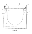
- the device 1 designated globally on the FIGS. 1 to 7 are intended for connection, according to the this non-limiting example of embodiment, of a grid 2 on a gutter 3.
- This rabbet is intended to cooperate in closure with the longitudinal edges 8 and 9 of said grid 2 and immobilize it by via elastically fastening means deformable adapted to make said grid 2 removable compared to the gutter 3.
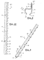
- each of the profiles 6, 7 includes, on the one hand, its part lower means 10, 11 anchor in the wings 4, 5 of the gutter 3 made in extension perpendicular down the branch horizontal "A" of the "L” constituting the profile 6 or 7 and secondly at its upper part of means 12 for anchoring at least one fastening clip 13 of grid 2 made by removal of matter on the vertical branch "B" of the "L” constituting the profile 6 or 7, said means anchoring 10, 11 of the profile 6 or 7 in the gutter 3 and said anchoring means 12 of the clip 13 in the section 6 or 7 being obtained with this one to form a monoblock element. (see figures 8, 9 and 10).
- the anchoring means 10, 11 of profiled in the wings 3, 4 of the gutter 3 are constituted by a series of legs directed towards the down from each of the longitudinal edges of the horizontal branch "A" of the "L” forming said profile, the legs 10 of one of the edges being made in a staggered way with a series of legs 11 on the other side. this is particularly well visible in Figure 10.
- each series of legs 10, 11 is made in the extension of a solid zone 14, 15 constituting their basis, in the extension perpendicular down the branch horizontal "A" of the "L” constituting the profile 5 or 6.
- all the legs 10, 11 of each the longitudinal edges are bent by relative to the solid zone 14, 15, to form a angle so that they are directed the one towards the other towards the interior of each wings 4, 5 of the gutter 3.
- each anchoring lugs 10, 11 of each series form a hook 16, 17 directed outwards gutter's wings while remaining contained in them.
- legs 10 and 11 are of different heights.
- the profile 6, 7 is obtained in one piece from a blank in rectangular sheet in which are made by cutting or punching the two sets of tabs 10, 11 and the lights 12 for clips 13, as well as by drilling a series of holes circular 18 for centering pins of the grid 2 or fixing screws complementary thereto, said profile 6, 7 being, successively to the machining operations, shaped by folding and against folding.
- clips 13 are made from a sheet of a material elastically deformable, conformed thereafter.
- each of the clips 13 presents a vertical branch 19 against bent to its part upper 20 to constitute a foot, dimensions and shapes such to be able to be introduced into the quadrangular lights 12 of profiled 6 or 7 that are intended for them and come in support behind the vertical branch "B" of it, the vertical retention of the clip 13 being ensured by a bearing of the part against bent 20 against the lower edge of the light 12 and a support of an upper portion 21 of the clip 13 against the upper edge of said light 12 after mounting, said upper portion 21 being constituted by two branches 22, 23 forming a elastic pin, one of which extends the part horizontal 20 of the foot and the other 23 free and inclined is the means of snapping proper on the grid 2 of the gutter 3.
- the grid 2 of gutter 3 has on its upper face a plurality of reservation 24 in number equal to that clips 13 to allow the housing of these in view of both vertical restraint and longitudinal of said grid 2.
- Ledit rim has a skin 26 to form a angle with a vertical wall 27 of the reservation, greater than 90 ° to make it easier the removal of the grid 2 after retraction of said free branch 23 of the clip 13.
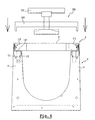
- the invention also relates to a tool 28 for dismantling and transporting a grid 2 attached to a gutter 3 via the connecting device described above.
- This tool 28 is constituted by a bridge 29 formed a horizontal crossbar and two feet vertical ends 30, 31, intended to be inserted in two opposite bookings 24 of the grid 2 between their vertical walls 27 and the free branches 23 clips 13 in place, in order to push these towards their disengagement from the 24.
- the extraction of grid 2 from Gutter 3 is made using a handle rotating 32 crossing the bridge 29 from its upper face via an axis rotary 33 whose lower end comprises two arms 34, 35 extending freely from each other and else of the axis 33.
- the free ends of the vertical feet 30, 31 of the bridge 29 each have a chamfer 36 directed inward to facilitate their introduction between the clip 13 of the profile 6 or 7 and the reservation 24 of the grid 2.
- the ends of the arms 34, 35 have chamfers 37 made on two upper angles diagonally opposite in order to facilitate their passage under the bars of grid 2 in view of his uprising.
- the clip 13 placed in profile 6 or 7 of the gutter 3 deforms during the placement of the grid 2.
- the clip 13 resumes its original position thereby retaining the grid 2.
- the device is then secure, the effort necessary to unlock the gate 2 being superior to that exercised by Grid 2 in its intended use.
- This lock also allows disassembly of the grid, if necessary, as already mentioned.
- the clip 13 is attached to the gutter 3 in being blocked, removably if necessary, in the profile 6, 7 thanks to its shape, but is not no case attached to the grid 2.
- the clip 13 is put in place on the profile before casting channel 3 of in order to prevent the cement from being lodged between profile walls and more particularly in the area of the light 12 in which must be inserted the tab 19 of the clip 13.
Landscapes
- Life Sciences & Earth Sciences (AREA)
- Engineering & Computer Science (AREA)
- Hydrology & Water Resources (AREA)
- Public Health (AREA)
- Water Supply & Treatment (AREA)
- Health & Medical Sciences (AREA)
- Supports For Pipes And Cables (AREA)
- Discharging, Photosensitive Material Shape In Electrophotography (AREA)
- Soil Working Implements (AREA)
- Baking, Grill, Roasting (AREA)
- Sink And Installation For Waste Water (AREA)
- Bathtub Accessories (AREA)
- Image-Pickup Tubes, Image-Amplification Tubes, And Storage Tubes (AREA)
- Connection Of Plates (AREA)
- Sewage (AREA)
Abstract
Description
Claims (15)
- Dispositif de liaison (1) d'un élément de. fermeture sur un réceptacle, notamment d'une grille (2) sur un caniveau (3), qui est constitué d'éléments monoblocs successifs, globalement en forme de « U » dont les ailes latérales sont coiffées à leurs extrémités supérieures de profilés métalliques (6 et 7) définissant des feuillures en « L » destinées à coopérer en fermeture avec les bords longitudinaux (8 et 9) de ladite grille (2) et à l'immobiliser, chacune desdites feuillures comportant d'une part à sa partie inférieure des moyens (10, 11) d'ancrage dans les ailes (4, 5) du caniveau (3) et d'autre part à sa partie supérieure des moyens de fixation élastiquement déformables aptes à rendre ladite grille (2) amovible, caractérisé en ce que les moyens de fixation sont constitués par au moins un clip (13) élastiquement déformable et par des moyens d'ancrage (12) de celui-ci, réalisés par enlèvement de matière sur la branche verticale « B » du « L » constituant le profilé (6 ou 7), lesdits moyens d'ancrage (10, 11) du profilé (6 ou 7) dans le caniveau (3) ainsi que lesdits moyens d'ancrage (12) du clip (13) dans le profilé (6 ou 7) étant obtenus avec celui-ci pour qu'il constitue un élément monobloc.
- Dispositif selon la revendication 1, caractérisé en que les moyens d'ancrage (10, 11) du profilé dans les ailes (3, 4) du caniveau (3) sont constitués par une série de pattes dirigées vers le bas issues de chacun des bords longitudinaux de la branche horizontale « A » du « L » formant ledit profilé, les pattes (10) de l'un des bords, étant réalisées de manière décalée avec une série de pattes (11) de l'autre bord.
- Dispositif selon la revendication 2, caractérisé en ce que chaque série de pattes (10, 11) est réalisée dans le prolongement d'une zone pleine (14, 15) constituant leur base, dans le prolongement perpendiculaire vers le bas de la branche horizontale « A » du « L », constituant le profilé (5 ou 6).
- Dispositif selon la revendication 3, caractérisé en ce que l'ensemble des pattes (10, 11) de chacun les bords longitudinaux sont recourbées par rapport à la zone pleine (14, 15), pour former un angle de manière à ce qu'elles soient dirigées les unes vers les autres vers l'intérieur de chacune des ailes (4, 5) du caniveau (3).
- Dispositif selon la revendication 4, caractérisé en ce que les extrémités de chacune des pattes d'ancrage (10, 11) de chacune des séries forme un crochet (16, 17) dirigé vers l'extérieur des ailes du caniveau tout en restant contenu dans celles-ci.
- Dispositif selon la revendication 1, caractérisé en ce que les moyens d'ancrage (12) des clips (13) dans la branche verticale « B » du « L » constituant le profilé sont constitués par des lumières quadrangulaires débouchantes ménagées dans ladite branche verticale « B ».
- Dispositif selon l'une des revendications 1 à 6, caractérisé en ce que le profilé (6, 7) est obtenu de manière monobloc à partir d'un flan en tôle rectangulaire dans lequel sont réalisées les deux séries de pattes (10, 11) et les lumières (12) destinées aux clips (13), ainsi qu'une série de trous circulaires (18) destinés à des pions de centrage de la grille (2) ou à des vis de fixation complémentaires de celle-ci, ledit profilé (6, 7) étant, successivement aux opérations d'usinage, conformé par pliage et contre pliage.
- Dispositif selon l'une des revendications 1 à 7, caractérisé en ce que chacun des clips (13) est réalisé à partir d'une feuille d'un matériau élastiquement déformable, conformé ensuite.
- Dispositif selon la revendication 8, caractérisé en ce que chacun des clips (13) présente une branche verticale (19) contre coudée à sa partie supérieure (20) pour constituer un pied, de dimensions et de formes telles à pouvoir être introduit dans les lumières quadrangulaires (12) du profilé (6 ou 7) qui leur sont destinées et venir en appui derrière la branche verticale « B » de celui-ci, la retenue verticale du clip (13) étant assurée par une prise d'appui de la partie contre coudée (20) contre le bord inférieur de la lumière (12) et une prise d'appui d'une partie supérieure (21) du clip (13) contre le bord supérieur de ladite lumière (12) après montage, ladite partie supérieure (21) étant constituée par deux branches (22, 23) formant une épingle élastique dont l'une (22) prolonge la partie horizontale (20) du pied et l'autre (23) libre et inclinée constitue le moyen d'encliquetage proprement dit sur la grille (2) du caniveau (3).
- Dispositif selon l'une des revendications 1 à 9, caractérisé en ce que la grille (2) du caniveau (3) comporte sur sa face supérieure une pluralité de réservation (24) en nombre égal à celui des clips (13) afin de permettre le logement de ceux-ci en vue de la retenue tant verticale que longitudinale de ladite grille (2).
- Dispositif selon les revendications 9 et 10, caractérisé en ce que l'extrémité de la branche libre (23) du clip (13) est recourbée (25) vers l'intérieur afin de permettre son glissement sur un rebord inférieur de la réservation (24) correspondante de la grille (2) et en ce que ledit rebord présente une dépouille (26) pour former un angle avec une paroi verticale (27) de la réservation, supérieur à 90° pour rendre plus aisée la dépose de la grille (2) après escamotage de ladite branche libre (23) du clip (13).
- Outil (28) destiné au démontage et au transport d'une grille (2) fixée à un caniveau (3) par l'intermédiaire d'un dispositif selon l'une des revendications 1 à 11, caractérisé en ce qu'il est constitué par un pont (29) formé d'une traverse horizontale et de deux pieds d'extrémité verticaux (30, 31), destinés à être insérés dans deux réservations opposées (24) de la grille (2) entre leurs parois verticales (27) et les branches libres (23) des clips (13) en place, afin de repousser celles-ci vers leur désengagement des réservations (24), l'extraction de la grille (2) du caniveau (3) s'effectuant à l'aide d'une poignée rotative (32) traversant le pont (29) à partir de sa face supérieure par l'intermédiaire d'un axe rotatif. (33) dont l'extrémité inférieure comporte deux bras (34, 35) s'étendant librement de part et d'autre de l'axe (33), les dimensions de ces bras (34, 35) et leur distance par rapport à la face inférieure du pont (29) sont telles qu'elles permettent audits bras (34, 35) d'être introduits entre deux barreaux de la grille (2) par le dessus puis être tournés selon un angle d'environ 90° sous lesdits barreaux en vu de pouvoir exercer une traction sur ceux-ci et conséquemment soulever la grille (2).
- Outil (28) selon la revendication 12, caractérisé en ce que les extrémités libres des pieds verticaux (30, 31) du pont (29) présentent chacune un chanfrein (36) dirigé vers l'intérieur afin de faciliter leur introduction entre le clip (13) du profilé (6 ou 7) et la réservation (24) de la grille (2).
- Outil (28) selon l'une des revendications 12 ou 13, caractérisé en ce que les extrémités des bras (34, 35) présentent des chanfreins (37) réalisés sur deux angles supérieurs diagonalement opposés afin de faciliter leur passage sous les barreaux de la grille (2) en vue de son soulèvement.
- Ensemble de caniveau (3) et grille d'obturation (2) de celui-ci, caractérisé en ce que l'un et l'autre comportent des moyens complémentaires d'assemblage selon l'une des revendications 1 à 11 du dispositif de liaison.
Applications Claiming Priority (2)
| Application Number | Priority Date | Filing Date | Title |
|---|---|---|---|
| FR0211742 | 2002-09-19 | ||
| FR0211742A FR2844814B1 (fr) | 2002-09-19 | 2002-09-19 | Dispositif de liaison d'une grille sur un caniveau et outil de demontage correspondant |
Publications (2)
| Publication Number | Publication Date |
|---|---|
| EP1400634A1 true EP1400634A1 (fr) | 2004-03-24 |
| EP1400634B1 EP1400634B1 (fr) | 2008-02-27 |
Family
ID=31897522
Family Applications (1)
| Application Number | Title | Priority Date | Filing Date |
|---|---|---|---|
| EP03291842A Expired - Lifetime EP1400634B1 (fr) | 2002-09-19 | 2003-07-25 | Dispositif de liaison d'une grille sur un caniveau et outil de demontage correspondant |
Country Status (5)
| Country | Link |
|---|---|
| EP (1) | EP1400634B1 (fr) |
| AT (1) | ATE387547T1 (fr) |
| DE (1) | DE60319315T2 (fr) |
| ES (1) | ES2300550T3 (fr) |
| FR (1) | FR2844814B1 (fr) |
Cited By (2)
| Publication number | Priority date | Publication date | Assignee | Title |
|---|---|---|---|---|
| RU2576268C1 (ru) * | 2015-01-26 | 2016-02-27 | Общество с ограниченной ответственностью "КапиталФорм" | Решетка дождеприемного канала |
| CN115180422A (zh) * | 2022-08-10 | 2022-10-14 | 北京达博有色金属焊料有限责任公司 | 一种叠套包装盒拆分机构及自动投料设备 |
Citations (4)
| Publication number | Priority date | Publication date | Assignee | Title |
|---|---|---|---|---|
| DE19511788C1 (de) * | 1995-03-30 | 1996-10-10 | Mea Meisinger Stahl & Kunststo | Lösbare Verriegelungsvorrichtung für einen befahrbaren Rost einer Entwässerungsrinne |
| EP0761885A1 (fr) * | 1995-09-08 | 1997-03-12 | Poly-Bauelemente AG | Dispositif de verrouillage d'une grille de recouvrement sur un caniveau d'écoulement |
| DE29808197U1 (de) * | 1998-05-07 | 1998-08-20 | Hauraton Betonwarenfabrik GmbH & Co KG, 76437 Rastatt | Entwässerungsrinne |
| WO2001094709A1 (fr) * | 2000-06-08 | 2001-12-13 | Broermann, Rita | Element de cheneau |
-
2002
- 2002-09-19 FR FR0211742A patent/FR2844814B1/fr not_active Expired - Lifetime
-
2003
- 2003-07-25 ES ES03291842T patent/ES2300550T3/es not_active Expired - Lifetime
- 2003-07-25 EP EP03291842A patent/EP1400634B1/fr not_active Expired - Lifetime
- 2003-07-25 AT AT03291842T patent/ATE387547T1/de not_active IP Right Cessation
- 2003-07-25 DE DE60319315T patent/DE60319315T2/de not_active Expired - Lifetime
Patent Citations (4)
| Publication number | Priority date | Publication date | Assignee | Title |
|---|---|---|---|---|
| DE19511788C1 (de) * | 1995-03-30 | 1996-10-10 | Mea Meisinger Stahl & Kunststo | Lösbare Verriegelungsvorrichtung für einen befahrbaren Rost einer Entwässerungsrinne |
| EP0761885A1 (fr) * | 1995-09-08 | 1997-03-12 | Poly-Bauelemente AG | Dispositif de verrouillage d'une grille de recouvrement sur un caniveau d'écoulement |
| DE29808197U1 (de) * | 1998-05-07 | 1998-08-20 | Hauraton Betonwarenfabrik GmbH & Co KG, 76437 Rastatt | Entwässerungsrinne |
| WO2001094709A1 (fr) * | 2000-06-08 | 2001-12-13 | Broermann, Rita | Element de cheneau |
Cited By (3)
| Publication number | Priority date | Publication date | Assignee | Title |
|---|---|---|---|---|
| RU2576268C1 (ru) * | 2015-01-26 | 2016-02-27 | Общество с ограниченной ответственностью "КапиталФорм" | Решетка дождеприемного канала |
| CN115180422A (zh) * | 2022-08-10 | 2022-10-14 | 北京达博有色金属焊料有限责任公司 | 一种叠套包装盒拆分机构及自动投料设备 |
| CN115180422B (zh) * | 2022-08-10 | 2023-09-12 | 北京达博有色金属焊料有限责任公司 | 一种叠套包装盒拆分机构及自动投料设备 |
Also Published As
| Publication number | Publication date |
|---|---|
| ATE387547T1 (de) | 2008-03-15 |
| DE60319315D1 (de) | 2008-04-10 |
| FR2844814B1 (fr) | 2005-04-22 |
| FR2844814A1 (fr) | 2004-03-26 |
| ES2300550T3 (es) | 2008-06-16 |
| EP1400634B1 (fr) | 2008-02-27 |
| DE60319315T2 (de) | 2009-02-26 |
Similar Documents
| Publication | Publication Date | Title |
|---|---|---|
| EP1525354B1 (fr) | Grille pour obturer un caniveau ou analogue | |
| EP1251284B1 (fr) | Ensemble de deux pièces de carrosserie à réunir bord à bord et pièce de carrosserie appartenant à un tel ensemble | |
| EP1251285B1 (fr) | Ensemble de deux pièces de carrosserie à réunir bord à bord et une pièce de carrosserie appartenant à un tel ensemble | |
| CA3032086A1 (fr) | Caisson de meuble | |
| EP1189323B1 (fr) | Dispositif pour l'implantation encastrée d'au moins un appareillage électrique dans un conduit de câblage de profondeur inférieure à celle de l'appareillage. | |
| EP3868267B1 (fr) | Réhausseur de wc et procédé de mise en place | |
| EP1400634B1 (fr) | Dispositif de liaison d'une grille sur un caniveau et outil de demontage correspondant | |
| CA2483088A1 (fr) | Accessoire d'angle pour goulottes comprenant deux volets assembles en biais | |
| EP1160382B1 (fr) | Regard à couvercle articulé à dispositif antivol, pour excavation de sol | |
| EP2746476A1 (fr) | Dispositif de couvercle à fente pour caniveau hydraulique | |
| FR3029550A1 (fr) | Dispositif de montage provisoire d'elements sur une poutre de structure de batiment | |
| FR2720770A1 (fr) | Chambre de tirage à couverture verrouillée pour câbles et canalisations. | |
| FR2846018A1 (fr) | Dispositif de fixation de panneaux solaires sur une toiture | |
| FR2710091A1 (fr) | Dispositif de mise en place et de positionnement d'armature dans des coffrages pour béton armé. | |
| EP2808465B1 (fr) | Structure pour bassin et couverture | |
| EP0698692B1 (fr) | Trappe, notamment pour regard technique de bouche d'incendie et ses éléments constitutifs | |
| FR3043640A1 (fr) | Systeme de fixation d’un article, notamment un element de bagagerie, sur un motocycle | |
| EP2491837A1 (fr) | Cabine de douche avec panneaux assemblés par emboitement | |
| EP2463529B1 (fr) | Dispositif de fixation avec verrouillage renforcé | |
| EP1617155B1 (fr) | Grille de ventilation | |
| FR2790520A1 (fr) | Dispositif de liaison d'un element de fermeture sur un receptacle, notamment d'une grille sur un caniveau | |
| FR3022277A1 (fr) | Ensemble de coffrage perdu prefabrique pour escalier en beton | |
| FR3029224A1 (fr) | Module d’ecoulement d’eaux destine a etre encastre dans un mur | |
| EP0983408A1 (fr) | Element de couverture | |
| FR3013375A1 (fr) | Dispositif de fixation d'un element de serrure |
Legal Events
| Date | Code | Title | Description |
|---|---|---|---|
| PUAI | Public reference made under article 153(3) epc to a published international application that has entered the european phase |
Free format text: ORIGINAL CODE: 0009012 |
|
| AK | Designated contracting states |
Kind code of ref document: A1 Designated state(s): AT BE BG CH CY CZ DE DK EE ES FI FR GB GR HU IE IT LI LU MC NL PT RO SE SI SK TR |
|
| AX | Request for extension of the european patent |
Extension state: AL LT LV MK |
|
| 17P | Request for examination filed |
Effective date: 20040717 |
|
| AKX | Designation fees paid |
Designated state(s): AT BE BG CH CY CZ DE DK EE ES FI FR GB GR HU IE IT LI LU MC NL PT RO SE SI SK TR |
|
| GRAP | Despatch of communication of intention to grant a patent |
Free format text: ORIGINAL CODE: EPIDOSNIGR1 |
|
| GRAS | Grant fee paid |
Free format text: ORIGINAL CODE: EPIDOSNIGR3 |
|
| GRAA | (expected) grant |
Free format text: ORIGINAL CODE: 0009210 |
|
| AK | Designated contracting states |
Kind code of ref document: B1 Designated state(s): AT BE BG CH CY CZ DE DK EE ES FI FR GB GR HU IE IT LI LU MC NL PT RO SE SI SK TR |
|
| REG | Reference to a national code |
Ref country code: GB Ref legal event code: FG4D Free format text: NOT ENGLISH |
|
| RTI1 | Title (correction) |
Free format text: SYSTEM FOR SECURING A GRATING TO A GUTTER AND A TOOL FOR REMOVING IT |
|
| REG | Reference to a national code |
Ref country code: CH Ref legal event code: EP |
|
| REG | Reference to a national code |
Ref country code: IE Ref legal event code: FG4D Free format text: LANGUAGE OF EP DOCUMENT: FRENCH |
|
| REF | Corresponds to: |
Ref document number: 60319315 Country of ref document: DE Date of ref document: 20080410 Kind code of ref document: P |
|
| REG | Reference to a national code |
Ref country code: CH Ref legal event code: NV Representative=s name: WILLIAM BLANC & CIE CONSEILS EN PROPRIETE INDUSTRI |
|
| REG | Reference to a national code |
Ref country code: ES Ref legal event code: FG2A Ref document number: 2300550 Country of ref document: ES Kind code of ref document: T3 |
|
| PG25 | Lapsed in a contracting state [announced via postgrant information from national office to epo] |
Ref country code: FI Free format text: LAPSE BECAUSE OF FAILURE TO SUBMIT A TRANSLATION OF THE DESCRIPTION OR TO PAY THE FEE WITHIN THE PRESCRIBED TIME-LIMIT Effective date: 20080227 |
|
| PG25 | Lapsed in a contracting state [announced via postgrant information from national office to epo] |
Ref country code: AT Free format text: LAPSE BECAUSE OF FAILURE TO SUBMIT A TRANSLATION OF THE DESCRIPTION OR TO PAY THE FEE WITHIN THE PRESCRIBED TIME-LIMIT Effective date: 20080227 |
|
| PG25 | Lapsed in a contracting state [announced via postgrant information from national office to epo] |
Ref country code: SI Free format text: LAPSE BECAUSE OF FAILURE TO SUBMIT A TRANSLATION OF THE DESCRIPTION OR TO PAY THE FEE WITHIN THE PRESCRIBED TIME-LIMIT Effective date: 20080227 |
|
| REG | Reference to a national code |
Ref country code: IE Ref legal event code: FD4D |
|
| PG25 | Lapsed in a contracting state [announced via postgrant information from national office to epo] |
Ref country code: SK Free format text: LAPSE BECAUSE OF FAILURE TO SUBMIT A TRANSLATION OF THE DESCRIPTION OR TO PAY THE FEE WITHIN THE PRESCRIBED TIME-LIMIT Effective date: 20080227 Ref country code: SE Free format text: LAPSE BECAUSE OF FAILURE TO SUBMIT A TRANSLATION OF THE DESCRIPTION OR TO PAY THE FEE WITHIN THE PRESCRIBED TIME-LIMIT Effective date: 20080527 Ref country code: PT Free format text: LAPSE BECAUSE OF FAILURE TO SUBMIT A TRANSLATION OF THE DESCRIPTION OR TO PAY THE FEE WITHIN THE PRESCRIBED TIME-LIMIT Effective date: 20080721 Ref country code: IE Free format text: LAPSE BECAUSE OF FAILURE TO SUBMIT A TRANSLATION OF THE DESCRIPTION OR TO PAY THE FEE WITHIN THE PRESCRIBED TIME-LIMIT Effective date: 20080227 Ref country code: DK Free format text: LAPSE BECAUSE OF FAILURE TO SUBMIT A TRANSLATION OF THE DESCRIPTION OR TO PAY THE FEE WITHIN THE PRESCRIBED TIME-LIMIT Effective date: 20080227 Ref country code: CZ Free format text: LAPSE BECAUSE OF FAILURE TO SUBMIT A TRANSLATION OF THE DESCRIPTION OR TO PAY THE FEE WITHIN THE PRESCRIBED TIME-LIMIT Effective date: 20080227 |
|
| PG25 | Lapsed in a contracting state [announced via postgrant information from national office to epo] |
Ref country code: RO Free format text: LAPSE BECAUSE OF FAILURE TO SUBMIT A TRANSLATION OF THE DESCRIPTION OR TO PAY THE FEE WITHIN THE PRESCRIBED TIME-LIMIT Effective date: 20080227 |
|
| PLBE | No opposition filed within time limit |
Free format text: ORIGINAL CODE: 0009261 |
|
| STAA | Information on the status of an ep patent application or granted ep patent |
Free format text: STATUS: NO OPPOSITION FILED WITHIN TIME LIMIT |
|
| 26N | No opposition filed |
Effective date: 20081128 |
|
| PG25 | Lapsed in a contracting state [announced via postgrant information from national office to epo] |
Ref country code: EE Free format text: LAPSE BECAUSE OF FAILURE TO SUBMIT A TRANSLATION OF THE DESCRIPTION OR TO PAY THE FEE WITHIN THE PRESCRIBED TIME-LIMIT Effective date: 20080227 Ref country code: BG Free format text: LAPSE BECAUSE OF FAILURE TO SUBMIT A TRANSLATION OF THE DESCRIPTION OR TO PAY THE FEE WITHIN THE PRESCRIBED TIME-LIMIT Effective date: 20080527 |
|
| PG25 | Lapsed in a contracting state [announced via postgrant information from national office to epo] |
Ref country code: CY Free format text: LAPSE BECAUSE OF FAILURE TO SUBMIT A TRANSLATION OF THE DESCRIPTION OR TO PAY THE FEE WITHIN THE PRESCRIBED TIME-LIMIT Effective date: 20080227 |
|
| REG | Reference to a national code |
Ref country code: CH Ref legal event code: PFA Owner name: PREFAEST S.A. Free format text: PREFAEST S.A.# #21270 MAXILLY-SUR-SAONE (FR) -TRANSFER TO- PREFAEST S.A.# #21270 MAXILLY-SUR-SAONE (FR) |
|
| PG25 | Lapsed in a contracting state [announced via postgrant information from national office to epo] |
Ref country code: HU Free format text: LAPSE BECAUSE OF FAILURE TO SUBMIT A TRANSLATION OF THE DESCRIPTION OR TO PAY THE FEE WITHIN THE PRESCRIBED TIME-LIMIT Effective date: 20080828 |
|
| PG25 | Lapsed in a contracting state [announced via postgrant information from national office to epo] |
Ref country code: TR Free format text: LAPSE BECAUSE OF FAILURE TO SUBMIT A TRANSLATION OF THE DESCRIPTION OR TO PAY THE FEE WITHIN THE PRESCRIBED TIME-LIMIT Effective date: 20080227 |
|
| PG25 | Lapsed in a contracting state [announced via postgrant information from national office to epo] |
Ref country code: GR Free format text: LAPSE BECAUSE OF FAILURE TO SUBMIT A TRANSLATION OF THE DESCRIPTION OR TO PAY THE FEE WITHIN THE PRESCRIBED TIME-LIMIT Effective date: 20080528 |
|
| REG | Reference to a national code |
Ref country code: CH Ref legal event code: PCAR Free format text: NOVAGRAAF SWITZERLAND SA;CHEMIN DE L'ECHO 3;1213 ONEX (CH) |
|
| PGFP | Annual fee paid to national office [announced via postgrant information from national office to epo] |
Ref country code: ES Payment date: 20150611 Year of fee payment: 13 Ref country code: GB Payment date: 20150527 Year of fee payment: 13 Ref country code: MC Payment date: 20150528 Year of fee payment: 13 |
|
| PGFP | Annual fee paid to national office [announced via postgrant information from national office to epo] |
Ref country code: IT Payment date: 20150727 Year of fee payment: 13 |
|
| REG | Reference to a national code |
Ref country code: FR Ref legal event code: PLFP Year of fee payment: 14 |
|
| GBPC | Gb: european patent ceased through non-payment of renewal fee |
Effective date: 20160725 |
|
| PG25 | Lapsed in a contracting state [announced via postgrant information from national office to epo] |
Ref country code: MC Free format text: LAPSE BECAUSE OF NON-PAYMENT OF DUE FEES Effective date: 20160801 |
|
| REG | Reference to a national code |
Ref country code: FR Ref legal event code: PLFP Year of fee payment: 15 |
|
| PG25 | Lapsed in a contracting state [announced via postgrant information from national office to epo] |
Ref country code: GB Free format text: LAPSE BECAUSE OF NON-PAYMENT OF DUE FEES Effective date: 20160725 |
|
| PG25 | Lapsed in a contracting state [announced via postgrant information from national office to epo] |
Ref country code: IT Free format text: LAPSE BECAUSE OF NON-PAYMENT OF DUE FEES Effective date: 20160725 |
|
| PG25 | Lapsed in a contracting state [announced via postgrant information from national office to epo] |
Ref country code: ES Free format text: LAPSE BECAUSE OF NON-PAYMENT OF DUE FEES Effective date: 20160726 |
|
| REG | Reference to a national code |
Ref country code: FR Ref legal event code: PLFP Year of fee payment: 16 |
|
| REG | Reference to a national code |
Ref country code: ES Ref legal event code: FD2A Effective date: 20181129 |
|
| PGFP | Annual fee paid to national office [announced via postgrant information from national office to epo] |
Ref country code: NL Payment date: 20220720 Year of fee payment: 20 |
|
| PGFP | Annual fee paid to national office [announced via postgrant information from national office to epo] |
Ref country code: LU Payment date: 20220720 Year of fee payment: 20 Ref country code: DE Payment date: 20220621 Year of fee payment: 20 |
|
| PGFP | Annual fee paid to national office [announced via postgrant information from national office to epo] |
Ref country code: FR Payment date: 20220719 Year of fee payment: 20 Ref country code: BE Payment date: 20220720 Year of fee payment: 20 |
|
| PGFP | Annual fee paid to national office [announced via postgrant information from national office to epo] |
Ref country code: CH Payment date: 20220728 Year of fee payment: 20 |
|
| REG | Reference to a national code |
Ref country code: DE Ref legal event code: R071 Ref document number: 60319315 Country of ref document: DE |
|
| REG | Reference to a national code |
Ref country code: NL Ref legal event code: MK Effective date: 20230724 |
|
| REG | Reference to a national code |
Ref country code: CH Ref legal event code: PL |
|
| REG | Reference to a national code |
Ref country code: BE Ref legal event code: MK Effective date: 20230725 |