EP1400647B1 - Trennwandelement mit einer oberen Tragvorrichtung und einer unteren Bodenführung - Google Patents
Trennwandelement mit einer oberen Tragvorrichtung und einer unteren Bodenführung Download PDFInfo
- Publication number
- EP1400647B1 EP1400647B1 EP03021257A EP03021257A EP1400647B1 EP 1400647 B1 EP1400647 B1 EP 1400647B1 EP 03021257 A EP03021257 A EP 03021257A EP 03021257 A EP03021257 A EP 03021257A EP 1400647 B1 EP1400647 B1 EP 1400647B1
- Authority
- EP
- European Patent Office
- Prior art keywords
- partition wall
- wall component
- profile
- profile leg
- leg
- Prior art date
- Legal status (The legal status is an assumption and is not a legal conclusion. Google has not performed a legal analysis and makes no representation as to the accuracy of the status listed.)
- Expired - Lifetime
Links
Images


Classifications
-
- E—FIXED CONSTRUCTIONS
- E05—LOCKS; KEYS; WINDOW OR DOOR FITTINGS; SAFES
- E05D—HINGES OR SUSPENSION DEVICES FOR DOORS, WINDOWS OR WINGS
- E05D15/00—Suspension arrangements for wings
- E05D15/06—Suspension arrangements for wings for wings sliding horizontally more or less in their own plane
- E05D15/0621—Details, e.g. suspension or supporting guides
- E05D15/0626—Details, e.g. suspension or supporting guides for wings suspended at the top
- E05D15/063—Details, e.g. suspension or supporting guides for wings suspended at the top on wheels with fixed axis
- E05D15/0634—Details, e.g. suspension or supporting guides for wings suspended at the top on wheels with fixed axis with height adjustment
-
- E—FIXED CONSTRUCTIONS
- E05—LOCKS; KEYS; WINDOW OR DOOR FITTINGS; SAFES
- E05D—HINGES OR SUSPENSION DEVICES FOR DOORS, WINDOWS OR WINGS
- E05D5/00—Construction of single parts, e.g. the parts for attachment
- E05D5/02—Parts for attachment, e.g. flaps
- E05D5/0246—Parts for attachment, e.g. flaps for attachment to glass panels
- E05D2005/0253—Parts for attachment, e.g. flaps for attachment to glass panels the panels having conical or stepped recesses
-
- E—FIXED CONSTRUCTIONS
- E05—LOCKS; KEYS; WINDOW OR DOOR FITTINGS; SAFES
- E05D—HINGES OR SUSPENSION DEVICES FOR DOORS, WINDOWS OR WINGS
- E05D5/00—Construction of single parts, e.g. the parts for attachment
- E05D5/02—Parts for attachment, e.g. flaps
- E05D5/0246—Parts for attachment, e.g. flaps for attachment to glass panels
-
- E—FIXED CONSTRUCTIONS
- E05—LOCKS; KEYS; WINDOW OR DOOR FITTINGS; SAFES
- E05Y—INDEXING SCHEME ASSOCIATED WITH SUBCLASSES E05D AND E05F, RELATING TO CONSTRUCTION ELEMENTS, ELECTRIC CONTROL, POWER SUPPLY, POWER SIGNAL OR TRANSMISSION, USER INTERFACES, MOUNTING OR COUPLING, DETAILS, ACCESSORIES, AUXILIARY OPERATIONS NOT OTHERWISE PROVIDED FOR, APPLICATION THEREOF
- E05Y2800/00—Details, accessories and auxiliary operations not otherwise provided for
- E05Y2800/67—Materials; Strength alteration thereof
- E05Y2800/672—Glass
-
- E—FIXED CONSTRUCTIONS
- E05—LOCKS; KEYS; WINDOW OR DOOR FITTINGS; SAFES
- E05Y—INDEXING SCHEME ASSOCIATED WITH SUBCLASSES E05D AND E05F, RELATING TO CONSTRUCTION ELEMENTS, ELECTRIC CONTROL, POWER SUPPLY, POWER SIGNAL OR TRANSMISSION, USER INTERFACES, MOUNTING OR COUPLING, DETAILS, ACCESSORIES, AUXILIARY OPERATIONS NOT OTHERWISE PROVIDED FOR, APPLICATION THEREOF
- E05Y2900/00—Application of doors, windows, wings or fittings thereof
- E05Y2900/10—Application of doors, windows, wings or fittings thereof for buildings or parts thereof
- E05Y2900/13—Type of wing
- E05Y2900/132—Doors
-
- E—FIXED CONSTRUCTIONS
- E05—LOCKS; KEYS; WINDOW OR DOOR FITTINGS; SAFES
- E05Y—INDEXING SCHEME ASSOCIATED WITH SUBCLASSES E05D AND E05F, RELATING TO CONSTRUCTION ELEMENTS, ELECTRIC CONTROL, POWER SUPPLY, POWER SIGNAL OR TRANSMISSION, USER INTERFACES, MOUNTING OR COUPLING, DETAILS, ACCESSORIES, AUXILIARY OPERATIONS NOT OTHERWISE PROVIDED FOR, APPLICATION THEREOF
- E05Y2900/00—Application of doors, windows, wings or fittings thereof
- E05Y2900/10—Application of doors, windows, wings or fittings thereof for buildings or parts thereof
- E05Y2900/13—Type of wing
- E05Y2900/148—Windows
- E05Y2900/15—Balcony glazing
Definitions
- the invention relates to a means of an upper support device to a Guide rail slidably guided and by means of a lower floor guide positively guided partition element, wherein the support device and the floor guide each having a vertically extending, the Partition element indirectly or directly adjacent, with the Partition element screwed laschenförmigen profile legs of a Have support profiles or a floor guide profile and the Carrying device with a horizontal profile leg and one on the horizontal profile leg adjoining vertical profile leg the upper end edge of the partition wall element and the bottom guide with a horizontal profile leg and one on the horizontal profile leg subsequent vertical profile leg the lower end edge the partition wall element engages.
- Partition wall elements of the aforementioned type are usually made Glass panes, which are combined to form full-coverage glass fronts or at open partition can be stored in a storage space.
- the attachment Gias disks on suitable support elements are made regularly via holes arranged in the glass pane.
- Fasteners or fasteners of a certain are subject to manufacturing tolerance, there is regularly the problem the hole in the glass with the axis of the fastener or bring clamping element in an aligned cover.
- the respective connection between the glass pane and the Befest Trentsoder Support element allows this, then one deviates here on the mounting or carrier element, d. H. the required tolerance compensation is placed in the mounting or support element.
- DE 38 14 535 A1 relates to a running device for a hanging Sliding wall, in which the sliding wall element by means of a supporting bolt attached to a carriage. The connection of the support bolt on Sliding wall element via a clamped onto the sliding wall element Profile strip.
- US Pat. No. 4,905,345 is concerned with one on a guide rail rolling door, with the door over vertically extending tabs is hung on the carriage.
- a device designed for the lining of a balcony, disclosed in US Patent 5 088 236.
- Das upper end edge of the partition wall element substantially U-shaped or L-shaped embracing support profile or the lower end of the in the same way encompassing floor guide profile lies with its horizontal Profile legs recognizable directly to the respective front edge.
- the connection of the support device or the floor guide with the Partition element thus leaves no, due to the prescribed Manufacturing tolerances, required tolerance compensation to.
- the invention solves the problem set with the features of claim 1.
- the invention proposes that between the pressure piece and the upper end edge and / or lower end edge the partition element an edge protection is arranged.
- the hole in the tab-shaped profile leg as vertical Slot is formed, wherein the slot in the manner of a keyhole (Bundbart) formed with a narrower and a wider area is and the retaining pin of the point holder has a bolt head, such that it is plugged through the wider area and the the narrower area delimiting section behind.
- the aforementioned Embodiment allows the above-described longitudinal displacement of strap-shaped profile leg with simultaneous subsequent non-positive Connection of the profile leg with the partition element.
- the horizontal profile leg of the floor guide profile two mutually parallel threaded holes for receiving clamping screws and one between the threaded holes arranged hole for receiving a in or on Having a bottom rail forcibly guided floor guide element.
- the floor guide element itself can be designed as desired.
- a support device and a floor guide proposed for a partition element by means of which at more reliable Connection between the support device and the floor guide with the partition element a simple, heavy-duty adjustment of Partition element, in particular a glass, the height is possible.
- Partition element in particular a glass
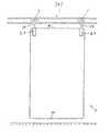
- An upper end edge of the partition wall element 1 is denoted by 11 and a lower end edge by 14.
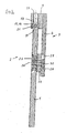
- the support profile 7 of the support device 2 of Figure 2 consists essentially from a tab-shaped profile leg 6, the - preferably in one piece - Is connected to a horizontal profile leg 9.
- the horizontal one Profile limb 9 overlaps the upper end edge 11 of FIG. 2 Not shown partition wall element 1.
- To the horizontal profile leg 9 is followed by a vertical profile leg 10, which - as in FIG 4 shows - the partition wall element 1 engages laterally.
- the kind of one Carrying head trained horizontal profile leg 9 has two parallel mutually extending distanced threaded holes 17, in the clamping screws Border 18. Between the threaded holes 17 is a larger bore 19 for receiving the support pin shown in Figure 1 20 arranged.
- the clamping screws 18 act on a pressure piece 15, which is formed as a pressure plate 16, and further on a, in particular in glass plates, advantageous edge protection 21, the in a groove 36 of the horizontal profile leg 9 is guided.
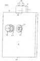
- a keyhole-like bore 25 which is the connection a generally designated 24 point holder is used.
- the Point holder 24 a retaining pin 23 with a bolt head 30, the so is shaped to be the wider area 29 of the vertical slot 27 trained bore 25 can pass through and, as Figure 4 recognize leaves, sunk at the narrower portion 28 of the vertical Langloches 27 can support.
- the dot holder 24 also has in known Make a cone nut 35, a conical glass guard 34th and a disk-shaped glass guard 33. As shown in FIG. 4.
- a Center longitudinal axis of the retaining bolt 23 is denoted by 26, so that the Retaining pin 23 aligned holes 25 in the spacer 22, the glass protection 33, the glass guard 34 and the cone nut 35 can pass through, as can be seen in particular from Figure 5.
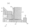
- a floor guide profile 8 corresponds to a floor guide 4 according to FIGS. 6 to 9 essentially the support profile 7 of the support device 2 with the Deviation that between the threaded holes 17 has a bore 31st is arranged, which is the inclusion of a bottom guide element 32nd serves.
- the horizontal profile leg 12 of the floor guide profile 8 is less strong than the horizontal with respect to its thigh thickness Profile leg 9 of the support device 2, because on the horizontal Profile leg 12 lower forces act.
- the support device 2 closes on the horizontal profile leg 12 also a vertical profile leg 13, so that too here a groove-like receptacle for the lower end edge 14 of the partition wall element 1 is formed.
Landscapes
- Engineering & Computer Science (AREA)
- Mechanical Engineering (AREA)
- Securing Of Glass Panes Or The Like (AREA)
- Specific Sealing Or Ventilating Devices For Doors And Windows (AREA)
- Packaging Frangible Articles (AREA)
- Floor Finish (AREA)
- Support Devices For Sliding Doors (AREA)
- Fittings On The Vehicle Exterior For Carrying Loads, And Devices For Holding Or Mounting Articles (AREA)
- Toys (AREA)
- Spinning Or Twisting Of Yarns (AREA)
Description
- Figur 1:
- Schematisch die Ansicht eines Trennwandelementes.
- Figur 2:
- Die Tragvorrichtung in einer perspektivischen Explosionszeichnung.
- Figur 3:
- Die schematische Ansicht eines Trennwandelementes nach Figur 1 in perspektivischer Darstellung mit einer Explosionszeichnung des Punkthalters.
- Figur 4:
- Eine Querschnittsansicht des Tragelementes gemäß Figur 2.
- Figur 5:
- In vergrößertem Maßstab eine hälftige Querschnittsansicht des Punkthalters.
- Figur 6:
- Eine Ansicht der Bodenführung.
- Figur 7:
- Einen Schnitt A-A nach Figur 6.
- Figur 8:
- Eine Seitenansicht der Bodenführung.
- Figur 9:
- Einen Schnitt B-B nach Figur 6.
- 1
- Trennwandelement
- 2
- Tragvorrichtung
- 3
- Führungsschiene
- 4
- Bodenführung
- 5
- Rollenwagen
- 6
- laschenförmiger Profilschenkel
- 7
- Tragprofil
- 8
- Bodenführungsprofil
- 9
- horizontaler Profilschenkel der Tragvorrichtung
- 10
- vertikaler Profilschenkel der Tragvorrichtung
- 11
- obere Stirnkante
- 12
- horizontaler Profilschenkel des Bodenführungsprofiles
- 13
- vertikaler Profilschenkel des Bodenführungsprofiles
- 14
- untere Stirnkante
- 15
- Druckstück
- 16
- Druckplatte
- 17
- Gewindebohrung
- 18
- Klemmschraube
- 19
- Bohrung
- 20
- Tragbolzen
- 21
- Kantenschutz
- 22
- Abstandshalter
- 23
- Haltebolzen
- 24
- Punkthalter
- 25
- Bohrungen
- 26
- Mittellängsachse
- 27
- vertikales Langloch
- 28
- schmalerer Bereich
- 29
- breiterer Bereich
- 30
- Bolzenkopf
- 31
- Bohrung
- 32
- Bodenführungselement
- 33
- Glasschutz
- 34
- Glasschutz
- 35
- Kegelmutter
- 36
- Nut
Claims (9)
- Mittels einer oberen Tragvorrichtung (2) an einer Führungsschiene (3) verschiebbar geführtes und mittels einer unteren Bodenführung (4) zwangsgeführtes Trennwandelement (1), wobei die Tragvorrichtung (2) und die Bodenführung (4) jeweils einen sich vertikal erstreckenden, dem Trennwandelement (1) mittelbar oder unmittelbar anliegenden, mit dem Trennwandelement (1) verschraubbaren laschenförmigen Profilschenkel (6) eines Tragprofiles (7) bzw. eines Bodenführungsprofiles (8) aufweisen und die Tragvorrichtung (2) mit einem horizontalen Profilschenkel (9) und einem an dem horizontalen Profilschenkel (9) anschließenden vertikalen Profilschenkel (10) die obere Stirnkante des Trennwandelementes (1) und die Bodenführung (4) mit einem horizontalen Profilschenkel (12) und einem an dem horizontalen Profilschenkel (12) anschließenden vertikalen Profilschenkel (13) die untere Stirnkante (14) des Trennwandelementes (1) umgreift, dadurch gekennzeichnet, dass der mit dem Trennwandelement (1) verschraubbare laschenförmige Profilschenkel (6) relativ zum Trennwandelement (1) begrenzt vertikal verschiebbar ist und die horizontalen Profilschenkel (9, 12) des Tragprofiles (7) und/oder des Bodenführungsprofiles (8) die obere und/oder untere Stirnkante (11, 14) des Trennwandelementes (1) mit Spiel übergreifen und zwischen dem horizontalen Profilschenkel (9, 12) und der Stirnkante (11, 14) ein gegen die Stimkante (11, 14) mittelbar oder unmittelbar anstellbares Druckstück (15) angeordnet ist
- Trennwandelement nach Anspruch 1, dadurch gekennzeichnet, dass das Druckstück (15) als Druckplatte (16) ausgebildet ist.
- Trennwandelement nach Anspruch 1 und 2, dadurch gekennzeichnet, dass der horizontale Profilschenkel (9) des Tragprofiles (7) und/oder der horizontale Profilschenkel (12) des Bodenführungsprofiles (8) jeweils wenigstens eine Gewindebohrung (17) für die Aufnahme eine gegen das Druckstück (15) anstellbaren Klemmschraube (18) aufweisen.
- Trennwandelement nach einem der Ansprüche 1 bis 3, dadurch gekennzeichnet, dass der horizontale Profilschenkel (9) des Tragprofiles (7) zwei parallel zueinander verlaufend angeordnete Gewindebohrungen (17) für die Aufnahme von Klemmschrauben (18) und eine zwischen den Gewindebohrungen (17) angeordnete Bohrung (19) für die Aufnahme eines Tragbolzens (20) aufweist.
- Trennwandelement nach einem der Ansprüche 1 bis 4, dadurch gekennzeichnet, dass zwischen dem Druckstück (15) und der oberen Stirnkante (11) und/oder unteren Stirnkante (14) des Trennwandelementes (1) ein Kantenschutz (21) angeordnet ist.
- Trennwandelement nach einem der Ansprüche 1 bis 5, dadurch gekennzeichnet, dass zwischen dem sich vertikal erstreckenden laschenförmigen Profilschenkel (6) der Tragvorrichtung (2) und dem Trennwandelement (1) ein Abstandshalter (22) angeordnet ist und das Trennwandelement (1), der Abstandshalter (22) und der laschenförmige Profilschenkel (6) von dem Haltebolzen (23) eines Punkthalters (24) durchfasste Bohrungen (25) aufweisen.
- Trennwandelement nach einem der Ansprüche 1 bis 6, dadurch gekennzeichnet, dass die Bohrung (25) im laschenförmigen Profilschenkel (6) als vertikales Langloch (27) ausgebildet ist.
- Trennwandelement nach Anspruch 7, dadurch gekennzeichnet, dass das Langloch (27) nach Art eines Schlüsselloches mit einem schmaleren und einem breiteren Bereich (28, 29) ausgebildet ist und der Haltebolzen (23) des Punkthalters (24) einen Bolzenkopf (30) aufweist, derart, dass er durch den breiteren Bereich (29) steckbar ist und den den schmaleren Bereich (28) begrenzenden Abschnitt hintergreift.
- Trennwandelement nach einem der Ansprüche 1 bis 8, dadurch gekennzeichnet, dass der horizontale Profilschenkel (12) des Bodenführungsprofiles (8) zwei parallel zueinander verlaufend angeordnete Gewindebohrungen (17) für die Aufnahme von Klemmschrauben (18) und eine zwischen den Gewindebohrungen (17) angeordnete Bohrung (31) für die Aufnahme eines in oder an einer Bodenführung zwangsführbaren Bodenführungselementes (32) aufweist.
Applications Claiming Priority (2)
| Application Number | Priority Date | Filing Date | Title |
|---|---|---|---|
| DE10243908 | 2002-09-20 | ||
| DE10243908A DE10243908B4 (de) | 2002-09-20 | 2002-09-20 | Mittels einer oberen Tragvorrichtung an einer Führungsschiene und mittels einer unteren Bodenführung zwangsgeführtes Trennwandelement |
Publications (2)
| Publication Number | Publication Date |
|---|---|
| EP1400647A1 EP1400647A1 (de) | 2004-03-24 |
| EP1400647B1 true EP1400647B1 (de) | 2005-05-18 |
Family
ID=31896265
Family Applications (1)
| Application Number | Title | Priority Date | Filing Date |
|---|---|---|---|
| EP03021257A Expired - Lifetime EP1400647B1 (de) | 2002-09-20 | 2003-09-19 | Trennwandelement mit einer oberen Tragvorrichtung und einer unteren Bodenführung |
Country Status (5)
| Country | Link |
|---|---|
| EP (1) | EP1400647B1 (de) |
| AT (1) | ATE295927T1 (de) |
| DE (2) | DE10243908B4 (de) |
| DK (1) | DK1400647T3 (de) |
| ES (1) | ES2239743T3 (de) |
Families Citing this family (2)
| Publication number | Priority date | Publication date | Assignee | Title |
|---|---|---|---|---|
| US10538947B2 (en) | 2016-03-07 | 2020-01-21 | Jeld-Wen, Inc. | Sliding barn door hardware |
| CN111535709A (zh) * | 2020-05-21 | 2020-08-14 | 重庆宏亚远桥金属制品有限责任公司 | 节能窗结构及其施工方法 |
Family Cites Families (9)
| Publication number | Priority date | Publication date | Assignee | Title |
|---|---|---|---|---|
| CH442067A (de) * | 1965-04-23 | 1967-08-15 | Idealheim Ag | Schiebetüre |
| US3796405A (en) * | 1972-10-16 | 1974-03-12 | Work Right Prod Inc | Roller bracket |
| FI78962C (fi) * | 1987-12-09 | 1989-10-10 | Lemminkaeinen Oy | Svaengbara glas foer balkong. |
| DE3814535A1 (de) * | 1988-03-29 | 1989-10-19 | Solbach Hans Joachim | Laufvorrichtung fuer eine haengende ein- oder mehrfluegelige schiebewand |
| US4905345A (en) * | 1989-03-09 | 1990-03-06 | Air-Lec Industries, Inc. | Track system for sliding door |
| DE19652773C2 (de) * | 1996-12-19 | 1998-11-26 | Dorma Gmbh & Co Kg | Klemmbeschlag für die Befestigung von Glasscheiben |
| DE29900640U1 (de) * | 1999-01-18 | 1999-04-01 | Dorma Gmbh + Co. Kg, 58256 Ennepetal | Duschabtrennung |
| US6336247B1 (en) * | 2000-05-08 | 2002-01-08 | Frank Schnoor | Screen door hanger assembly |
| DE20203070U1 (de) * | 2002-02-27 | 2003-07-24 | Hüppe Form Raumtrennsysteme GmbH, 26133 Oldenburg | Tragstück für die Befestigung von plattenförmigen Elementen, insbesondere Trennwandelementblättern |
-
2002
- 2002-09-20 DE DE10243908A patent/DE10243908B4/de not_active Expired - Fee Related
-
2003
- 2003-09-19 AT AT03021257T patent/ATE295927T1/de not_active IP Right Cessation
- 2003-09-19 DK DK03021257T patent/DK1400647T3/da active
- 2003-09-19 EP EP03021257A patent/EP1400647B1/de not_active Expired - Lifetime
- 2003-09-19 ES ES03021257T patent/ES2239743T3/es not_active Expired - Lifetime
- 2003-09-19 DE DE50300552T patent/DE50300552D1/de not_active Expired - Lifetime
Also Published As
| Publication number | Publication date |
|---|---|
| ES2239743T3 (es) | 2005-10-01 |
| DE10243908B4 (de) | 2004-11-18 |
| ATE295927T1 (de) | 2005-06-15 |
| DE10243908A1 (de) | 2004-04-15 |
| DE50300552D1 (de) | 2005-06-23 |
| EP1400647A1 (de) | 2004-03-24 |
| DK1400647T3 (da) | 2005-09-19 |
Similar Documents
| Publication | Publication Date | Title |
|---|---|---|
| DE19733367B4 (de) | Flügel für eine Tür, ein Fenster oder dergleichen | |
| DE2059829A1 (de) | Struktursystem fuer den Zusammenbau von vorgefertigten Konstruktionen | |
| EP2365167B1 (de) | Türband, insbesondere für Gebäudeabschlusstüren | |
| EP2927409B1 (de) | Dichtungsanordnung für eine schiebetür | |
| EP3767067A1 (de) | Bandseitige fingerschutzvorrichtung | |
| CH679060A5 (de) | ||
| EP2365166A2 (de) | Türband, insbesondere für Gebäudeabschlusstüren | |
| EP1400647B1 (de) | Trennwandelement mit einer oberen Tragvorrichtung und einer unteren Bodenführung | |
| EP0956799B1 (de) | Duschabtrennung | |
| EP3771793B1 (de) | Beschlag für eine schiebetür | |
| DE202022101255U1 (de) | Boden-/Deckensicherung mit einrastender Wandung | |
| DE4014106C2 (de) | Bodendichtungsleiste für eine Drehflügeltür | |
| EP0984126B1 (de) | Führungsanordnung für eine Schiebetür | |
| DE10323695B4 (de) | Schiebetürprofil | |
| DE19835684A1 (de) | Verfahrbare Türflügelanordnung | |
| EP1025790B1 (de) | Duschabtrennung | |
| DE29808586U1 (de) | Duschabtrennung | |
| DE2339623C3 (de) | Einstellbare Türaufhängevorrichtung | |
| EP0853179B1 (de) | Flügel für eine Tür, ein Fenster oder dergleichen | |
| DE10119994B4 (de) | Klemmhalter | |
| DE19940132C2 (de) | Gelenkband | |
| EP1574651B1 (de) | Duschabtrennung | |
| DE3026599C2 (de) | Haltevorrichtung für schienenförmige Gardinenleisten | |
| DE202015001607U1 (de) | Türband mit Anpressdruckverstellung | |
| DE2629354A1 (de) | Tuer, insbesondere fuer koksoefen, mit eigengewichtsverriegelung |
Legal Events
| Date | Code | Title | Description |
|---|---|---|---|
| PUAI | Public reference made under article 153(3) epc to a published international application that has entered the european phase |
Free format text: ORIGINAL CODE: 0009012 |
|
| AK | Designated contracting states |
Kind code of ref document: A1 Designated state(s): AT BE BG CH CY CZ DE DK EE ES FI FR GB GR HU IE IT LI LU MC NL PT RO SE SI SK TR |
|
| AX | Request for extension of the european patent |
Extension state: AL LT LV MK |
|
| GRAP | Despatch of communication of intention to grant a patent |
Free format text: ORIGINAL CODE: EPIDOSNIGR1 |
|
| 17P | Request for examination filed |
Effective date: 20040924 |
|
| AKX | Designation fees paid |
Designated state(s): AT BE BG CH CY CZ DE DK EE ES FI FR GB GR HU IE IT LI LU MC NL PT RO SE SI SK TR |
|
| GRAS | Grant fee paid |
Free format text: ORIGINAL CODE: EPIDOSNIGR3 |
|
| GRAA | (expected) grant |
Free format text: ORIGINAL CODE: 0009210 |
|
| AK | Designated contracting states |
Kind code of ref document: B1 Designated state(s): AT BE BG CH CY CZ DE DK EE ES FI FR GB GR HU IE IT LI LU MC NL PT RO SE SI SK TR |
|
| PG25 | Lapsed in a contracting state [announced via postgrant information from national office to epo] |
Ref country code: CZ Free format text: LAPSE BECAUSE OF FAILURE TO SUBMIT A TRANSLATION OF THE DESCRIPTION OR TO PAY THE FEE WITHIN THE PRESCRIBED TIME-LIMIT Effective date: 20050518 Ref country code: RO Free format text: LAPSE BECAUSE OF FAILURE TO SUBMIT A TRANSLATION OF THE DESCRIPTION OR TO PAY THE FEE WITHIN THE PRESCRIBED TIME-LIMIT Effective date: 20050518 Ref country code: IE Free format text: LAPSE BECAUSE OF FAILURE TO SUBMIT A TRANSLATION OF THE DESCRIPTION OR TO PAY THE FEE WITHIN THE PRESCRIBED TIME-LIMIT Effective date: 20050518 Ref country code: EE Free format text: LAPSE BECAUSE OF FAILURE TO SUBMIT A TRANSLATION OF THE DESCRIPTION OR TO PAY THE FEE WITHIN THE PRESCRIBED TIME-LIMIT Effective date: 20050518 Ref country code: SI Free format text: LAPSE BECAUSE OF FAILURE TO SUBMIT A TRANSLATION OF THE DESCRIPTION OR TO PAY THE FEE WITHIN THE PRESCRIBED TIME-LIMIT Effective date: 20050518 Ref country code: SK Free format text: LAPSE BECAUSE OF FAILURE TO SUBMIT A TRANSLATION OF THE DESCRIPTION OR TO PAY THE FEE WITHIN THE PRESCRIBED TIME-LIMIT Effective date: 20050518 |
|
| REG | Reference to a national code |
Ref country code: GB Ref legal event code: FG4D Free format text: NOT ENGLISH |
|
| REG | Reference to a national code |
Ref country code: CH Ref legal event code: EP |
|
| REG | Reference to a national code |
Ref country code: CH Ref legal event code: NV Representative=s name: BOVARD AG PATENTANWAELTE Ref country code: IE Ref legal event code: FG4D Free format text: LANGUAGE OF EP DOCUMENT: GERMAN |
|
| REG | Reference to a national code |
Ref country code: SE Ref legal event code: TRGR |
|
| REF | Corresponds to: |
Ref document number: 50300552 Country of ref document: DE Date of ref document: 20050623 Kind code of ref document: P |
|
| PG25 | Lapsed in a contracting state [announced via postgrant information from national office to epo] |
Ref country code: GR Free format text: LAPSE BECAUSE OF FAILURE TO SUBMIT A TRANSLATION OF THE DESCRIPTION OR TO PAY THE FEE WITHIN THE PRESCRIBED TIME-LIMIT Effective date: 20050818 Ref country code: BG Free format text: LAPSE BECAUSE OF FAILURE TO SUBMIT A TRANSLATION OF THE DESCRIPTION OR TO PAY THE FEE WITHIN THE PRESCRIBED TIME-LIMIT Effective date: 20050818 |
|
| PGFP | Annual fee paid to national office [announced via postgrant information from national office to epo] |
Ref country code: TR Payment date: 20050824 Year of fee payment: 5 |
|
| GBT | Gb: translation of ep patent filed (gb section 77(6)(a)/1977) |
Effective date: 20050823 |
|
| PG25 | Lapsed in a contracting state [announced via postgrant information from national office to epo] |
Ref country code: CY Free format text: LAPSE BECAUSE OF FAILURE TO SUBMIT A TRANSLATION OF THE DESCRIPTION OR TO PAY THE FEE WITHIN THE PRESCRIBED TIME-LIMIT Effective date: 20050919 Ref country code: AT Free format text: LAPSE BECAUSE OF NON-PAYMENT OF DUE FEES Effective date: 20050919 |
|
| REG | Reference to a national code |
Ref country code: DK Ref legal event code: T3 |
|
| PG25 | Lapsed in a contracting state [announced via postgrant information from national office to epo] |
Ref country code: MC Free format text: LAPSE BECAUSE OF NON-PAYMENT OF DUE FEES Effective date: 20050930 Ref country code: LU Free format text: LAPSE BECAUSE OF NON-PAYMENT OF DUE FEES Effective date: 20050930 |
|
| REG | Reference to a national code |
Ref country code: ES Ref legal event code: FG2A Ref document number: 2239743 Country of ref document: ES Kind code of ref document: T3 |
|
| PG25 | Lapsed in a contracting state [announced via postgrant information from national office to epo] |
Ref country code: PT Free format text: LAPSE BECAUSE OF FAILURE TO SUBMIT A TRANSLATION OF THE DESCRIPTION OR TO PAY THE FEE WITHIN THE PRESCRIBED TIME-LIMIT Effective date: 20051024 |
|
| PG25 | Lapsed in a contracting state [announced via postgrant information from national office to epo] |
Ref country code: HU Free format text: LAPSE BECAUSE OF FAILURE TO SUBMIT A TRANSLATION OF THE DESCRIPTION OR TO PAY THE FEE WITHIN THE PRESCRIBED TIME-LIMIT Effective date: 20051119 |
|
| REG | Reference to a national code |
Ref country code: IE Ref legal event code: FD4D |
|
| PLBE | No opposition filed within time limit |
Free format text: ORIGINAL CODE: 0009261 |
|
| STAA | Information on the status of an ep patent application or granted ep patent |
Free format text: STATUS: NO OPPOSITION FILED WITHIN TIME LIMIT |
|
| ET | Fr: translation filed | ||
| 26N | No opposition filed |
Effective date: 20060221 |
|
| PGFP | Annual fee paid to national office [announced via postgrant information from national office to epo] |
Ref country code: DK Payment date: 20070914 Year of fee payment: 5 |
|
| PGFP | Annual fee paid to national office [announced via postgrant information from national office to epo] |
Ref country code: ES Payment date: 20070927 Year of fee payment: 5 |
|
| PGFP | Annual fee paid to national office [announced via postgrant information from national office to epo] |
Ref country code: FI Payment date: 20070913 Year of fee payment: 5 |
|
| PGFP | Annual fee paid to national office [announced via postgrant information from national office to epo] |
Ref country code: GB Payment date: 20070914 Year of fee payment: 5 |
|
| PGFP | Annual fee paid to national office [announced via postgrant information from national office to epo] |
Ref country code: IT Payment date: 20070922 Year of fee payment: 5 Ref country code: SE Payment date: 20060914 Year of fee payment: 4 |
|
| PG25 | Lapsed in a contracting state [announced via postgrant information from national office to epo] |
Ref country code: SE Free format text: LAPSE BECAUSE OF NON-PAYMENT OF DUE FEES Effective date: 20070920 |
|
| EUG | Se: european patent has lapsed | ||
| REG | Reference to a national code |
Ref country code: DK Ref legal event code: EBP |
|
| GBPC | Gb: european patent ceased through non-payment of renewal fee |
Effective date: 20080919 |
|
| PG25 | Lapsed in a contracting state [announced via postgrant information from national office to epo] |
Ref country code: FI Free format text: LAPSE BECAUSE OF NON-PAYMENT OF DUE FEES Effective date: 20080919 |
|
| PG25 | Lapsed in a contracting state [announced via postgrant information from national office to epo] |
Ref country code: IT Free format text: LAPSE BECAUSE OF NON-PAYMENT OF DUE FEES Effective date: 20080919 |
|
| REG | Reference to a national code |
Ref country code: ES Ref legal event code: FD2A Effective date: 20080920 |
|
| PG25 | Lapsed in a contracting state [announced via postgrant information from national office to epo] |
Ref country code: GB Free format text: LAPSE BECAUSE OF NON-PAYMENT OF DUE FEES Effective date: 20080919 |
|
| PG25 | Lapsed in a contracting state [announced via postgrant information from national office to epo] |
Ref country code: ES Free format text: LAPSE BECAUSE OF NON-PAYMENT OF DUE FEES Effective date: 20080920 |
|
| PG25 | Lapsed in a contracting state [announced via postgrant information from national office to epo] |
Ref country code: DK Free format text: LAPSE BECAUSE OF NON-PAYMENT OF DUE FEES Effective date: 20090331 |
|
| REG | Reference to a national code |
Ref country code: CH Ref legal event code: PCOW Free format text: DORMA GMBH + CO. KG;DORMA PLATZ 1;58256 ENNEPETAL (DE) |
|
| PGFP | Annual fee paid to national office [announced via postgrant information from national office to epo] |
Ref country code: CH Payment date: 20100923 Year of fee payment: 8 |
|
| PGFP | Annual fee paid to national office [announced via postgrant information from national office to epo] |
Ref country code: FR Payment date: 20101005 Year of fee payment: 8 |
|
| PGFP | Annual fee paid to national office [announced via postgrant information from national office to epo] |
Ref country code: NL Payment date: 20100916 Year of fee payment: 8 |
|
| PGFP | Annual fee paid to national office [announced via postgrant information from national office to epo] |
Ref country code: BE Payment date: 20100913 Year of fee payment: 8 |
|
| REG | Reference to a national code |
Ref country code: CH Ref legal event code: PFA Owner name: DORMA GMBH + CO. KG Free format text: DORMA GMBH + CO. KG#DORMA PLATZ 1#58256 ENNEPETAL (DE) -TRANSFER TO- DORMA GMBH + CO. KG#DORMA PLATZ 1#58256 ENNEPETAL (DE) |
|
| PG25 | Lapsed in a contracting state [announced via postgrant information from national office to epo] |
Ref country code: TR Free format text: LAPSE BECAUSE OF NON-PAYMENT OF DUE FEES Effective date: 20100917 |
|
| BERE | Be: lapsed |
Owner name: *DORMA G.M.B.H. + CO. K.G. Effective date: 20110930 |
|
| REG | Reference to a national code |
Ref country code: NL Ref legal event code: V1 Effective date: 20120401 |
|
| REG | Reference to a national code |
Ref country code: CH Ref legal event code: PL |
|
| REG | Reference to a national code |
Ref country code: FR Ref legal event code: ST Effective date: 20120531 |
|
| PG25 | Lapsed in a contracting state [announced via postgrant information from national office to epo] |
Ref country code: BE Free format text: LAPSE BECAUSE OF NON-PAYMENT OF DUE FEES Effective date: 20110930 |
|
| PG25 | Lapsed in a contracting state [announced via postgrant information from national office to epo] |
Ref country code: LI Free format text: LAPSE BECAUSE OF NON-PAYMENT OF DUE FEES Effective date: 20110930 Ref country code: CH Free format text: LAPSE BECAUSE OF NON-PAYMENT OF DUE FEES Effective date: 20110930 Ref country code: NL Free format text: LAPSE BECAUSE OF NON-PAYMENT OF DUE FEES Effective date: 20120401 |
|
| PG25 | Lapsed in a contracting state [announced via postgrant information from national office to epo] |
Ref country code: FR Free format text: LAPSE BECAUSE OF NON-PAYMENT OF DUE FEES Effective date: 20110930 |
|
| PG25 | Lapsed in a contracting state [announced via postgrant information from national office to epo] |
Ref country code: TR Free format text: LAPSE BECAUSE OF NON-PAYMENT OF DUE FEES Effective date: 20080919 |
|
| REG | Reference to a national code |
Ref country code: DE Ref legal event code: R081 Ref document number: 50300552 Country of ref document: DE Owner name: DORMA DEUTSCHLAND GMBH, DE Free format text: FORMER OWNER: DORMA GMBH + CO. KG, 58256 ENNEPETAL, DE Effective date: 20141205 |
|
| REG | Reference to a national code |
Ref country code: DE Ref legal event code: R082 Ref document number: 50300552 Country of ref document: DE Representative=s name: BALDER IP LAW, S.L., ES |
|
| PGFP | Annual fee paid to national office [announced via postgrant information from national office to epo] |
Ref country code: DE Payment date: 20150922 Year of fee payment: 13 |
|
| REG | Reference to a national code |
Ref country code: DE Ref legal event code: R119 Ref document number: 50300552 Country of ref document: DE |
|
| PG25 | Lapsed in a contracting state [announced via postgrant information from national office to epo] |
Ref country code: DE Free format text: LAPSE BECAUSE OF NON-PAYMENT OF DUE FEES Effective date: 20170401 |