EP1400674A2 - Verfahren und Vorrichtung zur Steuerung einer Brennkraftmaschine - Google Patents
Verfahren und Vorrichtung zur Steuerung einer Brennkraftmaschine Download PDFInfo
- Publication number
- EP1400674A2 EP1400674A2 EP03015722A EP03015722A EP1400674A2 EP 1400674 A2 EP1400674 A2 EP 1400674A2 EP 03015722 A EP03015722 A EP 03015722A EP 03015722 A EP03015722 A EP 03015722A EP 1400674 A2 EP1400674 A2 EP 1400674A2
- Authority
- EP
- European Patent Office
- Prior art keywords
- data
- actuator
- control unit
- data carrier
- side switch
- Prior art date
- Legal status (The legal status is an assumption and is not a legal conclusion. Google has not performed a legal analysis and makes no representation as to the accuracy of the status listed.)
- Granted
Links
Images

Classifications
-
- F—MECHANICAL ENGINEERING; LIGHTING; HEATING; WEAPONS; BLASTING
- F02—COMBUSTION ENGINES; HOT-GAS OR COMBUSTION-PRODUCT ENGINE PLANTS
- F02D—CONTROLLING COMBUSTION ENGINES
- F02D41/00—Electrical control of supply of combustible mixture or its constituents
- F02D41/24—Electrical control of supply of combustible mixture or its constituents characterised by the use of digital means
- F02D41/2406—Electrical control of supply of combustible mixture or its constituents characterised by the use of digital means using essentially read only memories
- F02D41/2425—Particular ways of programming the data
-
- F—MECHANICAL ENGINEERING; LIGHTING; HEATING; WEAPONS; BLASTING
- F02—COMBUSTION ENGINES; HOT-GAS OR COMBUSTION-PRODUCT ENGINE PLANTS
- F02D—CONTROLLING COMBUSTION ENGINES
- F02D41/00—Electrical control of supply of combustible mixture or its constituents
- F02D41/24—Electrical control of supply of combustible mixture or its constituents characterised by the use of digital means
- F02D41/2406—Electrical control of supply of combustible mixture or its constituents characterised by the use of digital means using essentially read only memories
- F02D41/2425—Particular ways of programming the data
- F02D41/2429—Methods of calibrating or learning
- F02D41/2432—Methods of calibration
- F02D41/2435—Methods of calibration characterised by the writing medium, e.g. bar code
-
- F—MECHANICAL ENGINEERING; LIGHTING; HEATING; WEAPONS; BLASTING
- F02—COMBUSTION ENGINES; HOT-GAS OR COMBUSTION-PRODUCT ENGINE PLANTS
- F02D—CONTROLLING COMBUSTION ENGINES
- F02D41/00—Electrical control of supply of combustible mixture or its constituents
- F02D41/24—Electrical control of supply of combustible mixture or its constituents characterised by the use of digital means
- F02D41/2406—Electrical control of supply of combustible mixture or its constituents characterised by the use of digital means using essentially read only memories
- F02D41/2425—Particular ways of programming the data
- F02D41/2429—Methods of calibrating or learning
- F02D41/2451—Methods of calibrating or learning characterised by what is learned or calibrated
- F02D41/2464—Characteristics of actuators
- F02D41/2467—Characteristics of actuators for injectors
- F02D41/247—Behaviour for small quantities
-
- F—MECHANICAL ENGINEERING; LIGHTING; HEATING; WEAPONS; BLASTING
- F02—COMBUSTION ENGINES; HOT-GAS OR COMBUSTION-PRODUCT ENGINE PLANTS
- F02D—CONTROLLING COMBUSTION ENGINES
- F02D41/00—Electrical control of supply of combustible mixture or its constituents
- F02D41/20—Output circuits, e.g. for controlling currents in command coils
- F02D2041/202—Output circuits, e.g. for controlling currents in command coils characterised by the control of the circuit
- F02D2041/2024—Output circuits, e.g. for controlling currents in command coils characterised by the control of the circuit the control switching a load after time-on and time-off pulses
-
- F—MECHANICAL ENGINEERING; LIGHTING; HEATING; WEAPONS; BLASTING
- F02—COMBUSTION ENGINES; HOT-GAS OR COMBUSTION-PRODUCT ENGINE PLANTS
- F02D—CONTROLLING COMBUSTION ENGINES
- F02D41/00—Electrical control of supply of combustible mixture or its constituents
- F02D41/20—Output circuits, e.g. for controlling currents in command coils
- F02D2041/202—Output circuits, e.g. for controlling currents in command coils characterised by the control of the circuit
- F02D2041/2058—Output circuits, e.g. for controlling currents in command coils characterised by the control of the circuit using information of the actual current value
-
- F—MECHANICAL ENGINEERING; LIGHTING; HEATING; WEAPONS; BLASTING
- F02—COMBUSTION ENGINES; HOT-GAS OR COMBUSTION-PRODUCT ENGINE PLANTS
- F02D—CONTROLLING COMBUSTION ENGINES
- F02D41/00—Electrical control of supply of combustible mixture or its constituents
- F02D41/24—Electrical control of supply of combustible mixture or its constituents characterised by the use of digital means
- F02D41/2406—Electrical control of supply of combustible mixture or its constituents characterised by the use of digital means using essentially read only memories
- F02D41/2425—Particular ways of programming the data
- F02D41/2487—Methods for rewriting
Definitions
- the invention relates to a method and a device for controlling a Internal combustion engine according to the preambles of the independent claims.
- a control unit reads data from a data carrier and for control purposes used.
- the data carrier is assigned to at least one actuator and contains data that characterize this actuator. For example, it is provided that injectors that the internal combustion engine depending on a Measure control signal fuel, a data carrier is given, the Contains correction values with which errors of the individual injectors are compensated can.
- correction data at the end of the manufacture of the injector be determined and read into the data carrier.
- the disk can also be used as a Bar code or be designed as a readable memory element. In the first Initializing the control unit, these data are then read into the control unit and used in later operation to control the internal combustion engine.
- Modern control units contain various functions that also have correction values determine which are assigned to an injector. Such a function is for example referred to as zero quantity calibration. This data is usually only in the Control unit stored and used to control the internal combustion engine.
- the individual injection quantity of one injector is used in several Checkpoints recorded. The deviation of the respective injection quantity from the Setpoint determined.
- These data are recorded in a suitable form during injector production attached to the injector.
- the data is transmitted via suitable systems, for example via a camera system or transmit a diagnostic interface to the control unit.
- the data stored on the injector When the control unit is replaced, the data stored on the injector must be replaced can be read in again via the diagnostic interface or the camera system.
- the Other correction values already determined by the control unit would have to be from the old one Control unit read out and transferred to the new control unit. For this are again specific functions of the diagnostic interface and / or the control unit and / or the service tester is necessary. This creates when the control unit is replaced a considerable effort.
- correction values are stored in a non-volatile memory in the Injector itself and are deposited by the actual device at the Initialization of the control unit can be transmitted to the control unit.
- the problem that the other correction values when exchanging the Control unit lost can not be remedied with such a procedure become.
- control unit writes data into the data carrier is a simple one Control unit replacement possible in the event of a defect. It is an easy interchangeability parts, especially the control unit, without the use of specific, manufacturer-specific tools or testers.
- the data carrier forms a structural unit with the actuator. This enables the data to be safely assigned to the corresponding actuator. On Confusion of the data is not possible.
- the device is preferably used for an actuator which is used as an injector Injection of fuel is formed in the internal combustion engine.
- the procedure is combined with a method, in which the control device and the actuator via at least one data line and at least one further line are connected, with data from the control unit can be written into the data carrier and / or data from the control unit are readable from the data carrier.
- the at least one further line with ground and / or with for a predetermined period of time the supply voltage is connected. This means that before the start of the Data transmission a first line via a first switching means for the given one Time is connected to the supply voltage.
- the at least one further line with ground and / or with the Supply voltage is connected. This means that during data transfer a second line is connected to ground via a second switching means.
- the predetermined time period is selected so that the actuator does not respond.
- the Data transmission takes place in certain operating states.
- a device for controlling an internal combustion engine is shown.
- On Control unit is designated 100.
- An actuator is designated by 200.
- the control unit 100 contains a control unit 110, which in turn contains several functions. These include a so-called volume compensation regulation 112 and / or one Zero quantity calibration 114.
- the control unit acts on a first switching means 120, which is also referred to below as a high-side switch, and a second one Switching means 125, which is also referred to below as a low-side switch Drive signals.
- the first switching means is with its first connection with a Ubat supply voltage and with its second connection to the actuator connected.
- the second switching means is with its first connection to ground and to its second connection also with the actuator 200 via a low-side line 135 connected.
- the control unit of the control device is via a data line 140 connected to the actuator 200.
- Actuator 200 essentially includes mechanical ones, not shown and / or hydraulic components, a consumer 250 and a data carrier 260.
- the high-side line 130 is connected to the data carrier 260 and to the consumer 250 connected.
- the low-side line 135 is also connected to the consumer 250 and connected to disk 260.
- Data line 240 connects only that Control unit 110 with data carrier 260.
- the consumer 250 is in the illustrated embodiment as electromagnetic consumer, especially designed as a solenoid valve.
- the procedure according to the invention is shown only on the basis of a consumer.
- the procedure can also be transferred to several actuators. It can the actuator comprises one or more consumers.
- the consumer can do it be designed as a solenoid valve and / or as a piezo actuator.
- each actuator has a low-side switch assigned.
- the actuator is preferably an injector, the so-called Common rail systems are used, trained.
- the procedure is not limited to such injectors, it can also be used other actuators, such as pump-nozzle units, can be used.
- control unit provides control signals with which the high-side switch and / or the low-side switch are operated in such a way that the consumer is energized accordingly and the fuel metering for one releases a certain period of time from a certain point in time.
- the data carrier is preferably designed such that it is readable and writable. That the control unit can write data to the data carrier 260 and from that Read data carrier. It is preferably provided that the data carrier 260 is on Includes storage means and other elements for reading and / or writing the Memory are required.
- a Data line per actuator or one data line that connects all actuators is provided.
- the control unit contains various functions. This is, for example, an IMA procedure intended. With this method, the individual injection quantities of an injector at several test points. This test takes place in the Connection to the manufacture of the injectors. The deviations of the respective injection quantities from the setpoint. This information is sent to the injector given by means of a suitable data carrier. There are several Possibilities known. When the control unit is started up for the first time, the data read into the control unit in a suitable form and later for control purposes the internal combustion engine used. The injection quantity of the individual Corrected injectors by deliberately changing the control duration of the injector, that this measures the desired amount of fuel to be injected.
- NMK which is also known as Zero quantity calibration.
- the zero quantity determined is also referred to as the effective limit from which the injected one Fuel quantity triggers a torque formation perceptible in the speed signal.
- a quantity compensation regulation can also be provided, which also functions as a MAR function referred to as.
- a control is assigned to each cylinder, which a variable characterizing the speed to a common setpoint for all Cylinder adjusts.
- Such a quantity compensation regulation often includes a controller with integral part. The value of this integral component is characteristic of the Quantity error of the corresponding cylinder to which this controller is assigned. This is why these integral components of the individual controllers are usually also shown in stored in a non-volatile, rewritable memory.
- the data, the individual cylinders or Injectors can be assigned and usually in a non-volatile and / or rewritable memory are stored in the control unit, alternatively and / or additionally stored in the data carrier 260 of the respective actuator. That is, especially the data of the zero quantity calibration and the Equalization scheme and other procedures, the corresponding sizes, the Individual actuators can be assigned to the data carrier 260 enrolled.
- Control unit that ensures data integrity without additional measures and Means such as diagnostic testers must be provided.
- All data can be read and written as data carriers writable memory elements, in particular EEPROM memory can be used. This ensures that all functions, the individual data of the actuator can use. All adaptive algorithms, the data on the individual Determine actuators and save them in an optimal way for logistics perform a service-friendly manner.
- the data carrier is written and read via an additional one Data line 140.
- the data carrier also needs for reading in and reading out the data the memory still additional functional units with which the communication with the control unit can be guaranteed.
- the following must Procedure supported by the data carrier 260.
- the exchange of data preferably takes place in operating states in which no injection is possible, since for example, the rail pressure is too low. Such a condition is included, for example the initialization of the control unit and / or afterwards after the rail pressure has dropped. In these cases, an injection is hydraulically excluded. Recognize that Control unit or the control device that such a process is present is as follows proceed.
- both the high-side switch and the low-side switch closed. This causes current to flow through consumer 250 as it is would also take place when the consumer is controlled for injection. It is provided that the control of at least one of the switching means, i.e. either of High-side switch or the low-side switch, so short that the current flow cannot cause injection, i.e. the control takes so long that the Consumers do not respond to the current supply. It is corresponding to the Actuating only one actuator with a current pulse and thereby selected.
- the data carrier 260 recognizes this current flow
- the low-side switch remains closed when the data carrier is initialized. Preferably the high-side switch is opened again. From the time the high-side switch is closed, the data exchange takes place via the data line.
- a first measure is that communication is only in certain Operating states. Furthermore, it is provided that the activation time of the high-side switch is so short that the control is too short that a reaction of the Actuator can take place.
- No communication is preferably initialized during the injection, since here no signal is applied to the data line.
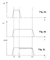
- FIG. 2a A corresponding signal curve is shown as an example in FIG. 2.
- Figure 2a is the Switching state of the high-side switch
- Figure 2b the state of the low-side switch and the state of the data line 140 is plotted against the time T in FIG. 2c.
- To the Time T1 is an operating state in which data transmission is possible. From this point on, both the high-side switch and the low-side switch are switched on brought a conductive state. The data line is also active. From the At time T2, the high-side switch returns to its non-conductive state brought.
- the data carrier 260 recognizes that a data transmission will take place soon. This Detection preferably takes place when the data line, as is the case here, is active and the pulse is of short duration.
- This state of the announced data transmission differs from the state of Actuation of the consumer in that the data line is active here and that certain operating conditions exist.
- the high-side and low-side switches operate, i.e. are in the conductive state. This is also the case with the usual control. That by pressing the high-side switch and the low-side switch, the consumer 250 is usually energized.
- the procedure according to the invention was based on the example of a consumer who is equipped with a solenoid valve. It is per group of consumers only one high-side switch and one low-side switch for each consumer. Alternatively, it can also be provided that the function of the high-side switch and the Low-side switch are reversed. The procedure is also applicable if only one switching means per consumer is provided.
- actuators Include solenoid valve, limited. It can also be used with other actuators, can be used, for example, in actuators that comprise a piezo actuator.
Landscapes
- Engineering & Computer Science (AREA)
- Chemical & Material Sciences (AREA)
- Combustion & Propulsion (AREA)
- Mechanical Engineering (AREA)
- General Engineering & Computer Science (AREA)
- Combined Controls Of Internal Combustion Engines (AREA)
- Electrical Control Of Air Or Fuel Supplied To Internal-Combustion Engine (AREA)
- Fuel-Injection Apparatus (AREA)
Abstract
Description
- Figur 1
- ein Blockdiagramm der wesentlichen Elemente der erfindungsgemäßen Vorgehensweise und
- Figur 2
- verschiedene über Zeit aufgetragene Signale.
Claims (5)
- Verfahren zur Steuerung einer Brennkraftmaschine, bei dem ein Steuergerät Daten aus einem Datenträger ausliest und zur Steuerung verwendet, wobei der Datenträger wenigstens einem Stellglied zugeordnet ist und dieses Stellglied charakterisierende Daten beinhaltet, dadurch gekennzeichnet, dass Daten von dem Steuergerät in den Datenträger einschreibbar sind.
- Verfahren nach Anspruch 1, dadurch gekennzeichnet, dass die Daten einer Nullmengenkalibrierung und/oder einer Mengenausgleichsregelung einschreibbar sind.
- Vorrichtung zur Steuerung einer Brennkraftmaschine, bei dem ein Steuergerät Daten aus einem Datenträger ausliest und zur Steuerung verwendet, wobei der Datenträger wenigstens einem Stellglied zugeordnet ist und dieses Stellglied charakterisierende Daten beinhaltet, dadurch gekennzeichnet, dass das Steuergerät Daten in den Datenträger einschreibt.
- Vorrichtung nach Anspruch 3, dadurch gekennzeichnet, dass der Datenträger eine bauliche Einheit mit dem Stellglied bildet.
- Vorrichtung nach Anspruch 3 oder 4, dadurch gekennzeichnet, dass das Stellglied als Injektor zur Einspritzung von Kraftstoff in die Brennkraftmaschine ausgebildet ist.
Applications Claiming Priority (2)
| Application Number | Priority Date | Filing Date | Title |
|---|---|---|---|
| DE2002144091 DE10244091A1 (de) | 2002-09-23 | 2002-09-23 | Verfahren und Vorrichtung zur Steuerung einer Brennkraftmaschine |
| DE10244091 | 2002-09-23 |
Publications (3)
| Publication Number | Publication Date |
|---|---|
| EP1400674A2 true EP1400674A2 (de) | 2004-03-24 |
| EP1400674A3 EP1400674A3 (de) | 2004-04-21 |
| EP1400674B1 EP1400674B1 (de) | 2005-11-02 |
Family
ID=31896290
Family Applications (1)
| Application Number | Title | Priority Date | Filing Date |
|---|---|---|---|
| EP20030015722 Expired - Lifetime EP1400674B1 (de) | 2002-09-23 | 2003-07-10 | Verfahren und Vorrichtung zur Steuerung einer Brennkraftmaschine |
Country Status (3)
| Country | Link |
|---|---|
| EP (1) | EP1400674B1 (de) |
| JP (1) | JP2004116523A (de) |
| DE (2) | DE10244091A1 (de) |
Cited By (10)
| Publication number | Priority date | Publication date | Assignee | Title |
|---|---|---|---|---|
| FR2876743A1 (fr) * | 2004-10-16 | 2006-04-21 | Bosch Gmbh Robert | Procede de correction du comportement d'injection d'un injecteur |
| EP1826386A1 (de) | 2006-02-24 | 2007-08-29 | Beru Aktiengesellschaft | Verbrennungsmotor für Fahrzeuge, insbesondere Dieselmotor |
| WO2009141183A1 (de) * | 2008-05-21 | 2009-11-26 | Continental Automotive Gmbh | Verfahren zur injektorindividuellen anpassung der einspritzzeit von kraftfahrzeugen |
| WO2012059305A1 (de) * | 2010-11-03 | 2012-05-10 | Robert Bosch Gmbh | Verfahren zum betreiben eines magnetischen schaltgliedes |
| WO2012059304A1 (de) * | 2010-11-03 | 2012-05-10 | Robert Bosch Gmbh | Verfahren zum betreiben eines schaltgliedes |
| EP3159534A4 (de) * | 2014-06-23 | 2018-02-28 | Hino Motors, Ltd. | Kraftstoffeinspritzsystem vom common-rail-typ |
| WO2018059970A1 (en) * | 2016-09-27 | 2018-04-05 | Delphi Technologies Ip Limited | Method for communicating data between a smart fuel injector and an ecu |
| WO2019130892A1 (ja) * | 2017-12-26 | 2019-07-04 | 株式会社デンソー | 負荷駆動装置 |
| EP3698034A1 (de) * | 2017-10-18 | 2020-08-26 | Delphi Automotive Systems Luxembourg SA | Anordnung zur übertragung von daten von einer elektronischen steuereinheit zu einem kraftstoffinjektor |
| CN113931760A (zh) * | 2021-09-26 | 2022-01-14 | 东风商用车有限公司 | 一种燃气发动机喷嘴的加电脉宽修正校验方法及系统 |
Families Citing this family (6)
| Publication number | Priority date | Publication date | Assignee | Title |
|---|---|---|---|---|
| DE102004053266A1 (de) | 2004-11-04 | 2006-05-11 | Robert Bosch Gmbh | Vorrichtung und Verfahren zum Korrigieren des Einspritzverhaltens eines Injektors |
| DE102005001425A1 (de) * | 2005-01-12 | 2006-07-20 | Robert Bosch Gmbh | Vorrichtung zur Steuerung einer Brennkraftmaschine |
| DE102007018627B4 (de) | 2007-04-19 | 2009-08-06 | Continental Automotive France | Verfahren und Vorrichtung zum Kalibrieren von Stellgliedern für Brennkraftmaschinen |
| DE102007019099B4 (de) | 2007-04-23 | 2016-12-15 | Continental Automotive Gmbh | Verfahren und Vorrichtung zur Kalibrierung von Kraftstoffinjektoren |
| DE102007020061B3 (de) | 2007-04-27 | 2008-10-16 | Siemens Ag | Verfahren und Datenträger zum Auslesen und/oder Speichern von injektorspezifischen Daten zur Steuerung eines Einspritzsystems einer Brennkraftmaschine |
| JP6380224B2 (ja) * | 2015-05-12 | 2018-08-29 | 株式会社デンソー | 噴射制御装置 |
Family Cites Families (3)
| Publication number | Priority date | Publication date | Assignee | Title |
|---|---|---|---|---|
| JPH076434B2 (ja) * | 1991-10-09 | 1995-01-30 | 株式会社ゼクセル | 電子式燃料噴射装置 |
| JP3487207B2 (ja) * | 1999-02-01 | 2004-01-13 | 株式会社デンソー | 燃料噴射システム |
| DE10215610B4 (de) * | 2001-04-10 | 2018-12-13 | Robert Bosch Gmbh | System und Verfahren zum Korrigieren des Einspritzverhaltens von mindestens einem Injektor |
-
2002
- 2002-09-23 DE DE2002144091 patent/DE10244091A1/de not_active Withdrawn
-
2003
- 2003-07-10 EP EP20030015722 patent/EP1400674B1/de not_active Expired - Lifetime
- 2003-07-10 DE DE50301536T patent/DE50301536D1/de not_active Expired - Lifetime
- 2003-09-22 JP JP2003330253A patent/JP2004116523A/ja active Pending
Cited By (15)
| Publication number | Priority date | Publication date | Assignee | Title |
|---|---|---|---|---|
| FR2876743A1 (fr) * | 2004-10-16 | 2006-04-21 | Bosch Gmbh Robert | Procede de correction du comportement d'injection d'un injecteur |
| US8036819B2 (en) | 2006-02-24 | 2011-10-11 | Beru Aktiengesellschaft | Internal combustion engine for vehicles, in particular a diesel engine |
| EP1826386A1 (de) | 2006-02-24 | 2007-08-29 | Beru Aktiengesellschaft | Verbrennungsmotor für Fahrzeuge, insbesondere Dieselmotor |
| US8775058B2 (en) | 2008-05-21 | 2014-07-08 | Continental Automotive Gmbh | Method for the injector-individual adaption of the injection time of motor vehicles |
| WO2009141183A1 (de) * | 2008-05-21 | 2009-11-26 | Continental Automotive Gmbh | Verfahren zur injektorindividuellen anpassung der einspritzzeit von kraftfahrzeugen |
| WO2012059305A1 (de) * | 2010-11-03 | 2012-05-10 | Robert Bosch Gmbh | Verfahren zum betreiben eines magnetischen schaltgliedes |
| WO2012059304A1 (de) * | 2010-11-03 | 2012-05-10 | Robert Bosch Gmbh | Verfahren zum betreiben eines schaltgliedes |
| US9624884B2 (en) | 2010-11-03 | 2017-04-18 | Robert Bosch Gmbh | Method for operating a magnetic switching element |
| US9766290B2 (en) | 2010-11-03 | 2017-09-19 | Robert Bosch Gmbh | Method for operating a switching element |
| EP3159534A4 (de) * | 2014-06-23 | 2018-02-28 | Hino Motors, Ltd. | Kraftstoffeinspritzsystem vom common-rail-typ |
| WO2018059970A1 (en) * | 2016-09-27 | 2018-04-05 | Delphi Technologies Ip Limited | Method for communicating data between a smart fuel injector and an ecu |
| EP3698034A1 (de) * | 2017-10-18 | 2020-08-26 | Delphi Automotive Systems Luxembourg SA | Anordnung zur übertragung von daten von einer elektronischen steuereinheit zu einem kraftstoffinjektor |
| WO2019130892A1 (ja) * | 2017-12-26 | 2019-07-04 | 株式会社デンソー | 負荷駆動装置 |
| CN113931760A (zh) * | 2021-09-26 | 2022-01-14 | 东风商用车有限公司 | 一种燃气发动机喷嘴的加电脉宽修正校验方法及系统 |
| CN113931760B (zh) * | 2021-09-26 | 2023-09-29 | 东风商用车有限公司 | 一种燃气发动机喷嘴的加电脉宽修正校验方法及系统 |
Also Published As
| Publication number | Publication date |
|---|---|
| EP1400674A3 (de) | 2004-04-21 |
| JP2004116523A (ja) | 2004-04-15 |
| EP1400674B1 (de) | 2005-11-02 |
| DE50301536D1 (de) | 2005-12-08 |
| DE10244091A1 (de) | 2004-04-01 |
Similar Documents
| Publication | Publication Date | Title |
|---|---|---|
| EP1400674B1 (de) | Verfahren und Vorrichtung zur Steuerung einer Brennkraftmaschine | |
| EP1809884B1 (de) | Vorrichtung und verfahren zum korrigieren des einspritzverhaltens eines injektors | |
| DE102007019099A1 (de) | Verfahren und Vorrichtung zur Kalibrierung von Kraftstoffinjektoren | |
| DE102010017368A1 (de) | Datenspeichervorrichtung | |
| EP1172541B1 (de) | Piezoelektrischer Aktor eines Einspritzventils sowie Kraftstoffeinspritzsystem | |
| EP1400678B1 (de) | Verfahren und Vorrichtung zur Steuerung einer Brennkraftmaschine | |
| DE19611885A1 (de) | Verfahren und Vorrichtung zur Steuerung eines elektromagnetischen Schaltorgans | |
| DE60011993T2 (de) | Apparat und Methode für das Ermitteln einer Verringerung der Kapazität während des Antriebes von piezoelektrischen Elementen | |
| DE102004023545A1 (de) | Verfahren zur Ermittlung der Position eines beweglichen Verschlusselementes eines Einspritzventils | |
| DE102018221683A1 (de) | Verfahren zum Betreiben eines Kraftstoffeinspritzsystems eines Kraftfahrzeugs und Kraftstoffeinspritzsystem | |
| DE102005050338A1 (de) | Verfahren zum Überprüfen eines Ventils | |
| EP1745203B1 (de) | Verfahren zur diagnose einer ansteuerschaltung | |
| WO2007104770A1 (de) | Verfahren und vorrichtung zum kalibrieren eines piezo-aktuators | |
| DE19958406A1 (de) | Verfahren und Vorrichtung zur Steuerung eines Stellers mit einem kapazitiven Element | |
| DE102008054409A1 (de) | Verfahren und Vorrichtung zur Steuerung einer Brennkraftmaschine | |
| DE19801187B4 (de) | Verfahren und Vorrichtung zum Betreiben einer Brennkraftmaschine | |
| EP1651851A1 (de) | Stellverfahren und stellvorrichtung für einen aktor | |
| DE102013101918B4 (de) | Kraftstoffeinspritzsystem ausgestattet mit einem Injektor und einem aufgenommenen Sensor | |
| EP1375882A1 (de) | Verfahren zum Betreiben einer Brennkraftmaschine insbesondere eines Kraftfahrzeugs | |
| DE102006039985A1 (de) | Kommunikationsvorrichtung und Datenübertragungsverfahren | |
| DE19854306A1 (de) | Steller mit kapazitivem Element | |
| DE102005001426A1 (de) | Verfahren zur Steuerung einer Brennkraftmaschine | |
| DE102007020061B3 (de) | Verfahren und Datenträger zum Auslesen und/oder Speichern von injektorspezifischen Daten zur Steuerung eines Einspritzsystems einer Brennkraftmaschine | |
| WO2005010335A2 (de) | Schaltungsanordnung und verfahren zum betreiben einer injektoranordnung sowie injektor | |
| DE102019003815B4 (de) | Verfahren zur Überwachung eines Injektors auf mechanische Schädigung |
Legal Events
| Date | Code | Title | Description |
|---|---|---|---|
| PUAI | Public reference made under article 153(3) epc to a published international application that has entered the european phase |
Free format text: ORIGINAL CODE: 0009012 |
|
| PUAL | Search report despatched |
Free format text: ORIGINAL CODE: 0009013 |
|
| AK | Designated contracting states |
Kind code of ref document: A2 Designated state(s): AT BE BG CH CY CZ DE DK EE ES FI FR GB GR HU IE IT LI LU MC NL PT RO SE SI SK TR |
|
| AX | Request for extension of the european patent |
Extension state: AL LT LV MK |
|
| AK | Designated contracting states |
Kind code of ref document: A3 Designated state(s): AT BE BG CH CY CZ DE DK EE ES FI FR GB GR HU IE IT LI LU MC NL PT RO SE SI SK TR |
|
| AX | Request for extension of the european patent |
Extension state: AL LT LV MK |
|
| RIC1 | Information provided on ipc code assigned before grant |
Ipc: 7F 02D 41/24 B Ipc: 7F 02D 41/14 A |
|
| 17P | Request for examination filed |
Effective date: 20041021 |
|
| AKX | Designation fees paid |
Designated state(s): DE FR GB IT |
|
| 17Q | First examination report despatched |
Effective date: 20041214 |
|
| GRAP | Despatch of communication of intention to grant a patent |
Free format text: ORIGINAL CODE: EPIDOSNIGR1 |
|
| GRAS | Grant fee paid |
Free format text: ORIGINAL CODE: EPIDOSNIGR3 |
|
| GRAA | (expected) grant |
Free format text: ORIGINAL CODE: 0009210 |
|
| AK | Designated contracting states |
Kind code of ref document: B1 Designated state(s): DE FR GB IT |
|
| REG | Reference to a national code |
Ref country code: GB Ref legal event code: FG4D Free format text: NOT ENGLISH |
|
| REF | Corresponds to: |
Ref document number: 50301536 Country of ref document: DE Date of ref document: 20051208 Kind code of ref document: P |
|
| GBT | Gb: translation of ep patent filed (gb section 77(6)(a)/1977) |
Effective date: 20060216 |
|
| ET | Fr: translation filed | ||
| PLBE | No opposition filed within time limit |
Free format text: ORIGINAL CODE: 0009261 |
|
| STAA | Information on the status of an ep patent application or granted ep patent |
Free format text: STATUS: NO OPPOSITION FILED WITHIN TIME LIMIT |
|
| 26N | No opposition filed |
Effective date: 20060803 |
|
| REG | Reference to a national code |
Ref country code: FR Ref legal event code: PLFP Year of fee payment: 13 |
|
| PGFP | Annual fee paid to national office [announced via postgrant information from national office to epo] |
Ref country code: GB Payment date: 20150724 Year of fee payment: 13 |
|
| PGFP | Annual fee paid to national office [announced via postgrant information from national office to epo] |
Ref country code: FR Payment date: 20150730 Year of fee payment: 13 |
|
| PGFP | Annual fee paid to national office [announced via postgrant information from national office to epo] |
Ref country code: IT Payment date: 20150728 Year of fee payment: 13 |
|
| PGFP | Annual fee paid to national office [announced via postgrant information from national office to epo] |
Ref country code: DE Payment date: 20160927 Year of fee payment: 14 |
|
| GBPC | Gb: european patent ceased through non-payment of renewal fee |
Effective date: 20160710 |
|
| PG25 | Lapsed in a contracting state [announced via postgrant information from national office to epo] |
Ref country code: FR Free format text: LAPSE BECAUSE OF NON-PAYMENT OF DUE FEES Effective date: 20160801 |
|
| REG | Reference to a national code |
Ref country code: FR Ref legal event code: ST Effective date: 20170331 |
|
| PG25 | Lapsed in a contracting state [announced via postgrant information from national office to epo] |
Ref country code: GB Free format text: LAPSE BECAUSE OF NON-PAYMENT OF DUE FEES Effective date: 20160710 |
|
| PG25 | Lapsed in a contracting state [announced via postgrant information from national office to epo] |
Ref country code: IT Free format text: LAPSE BECAUSE OF NON-PAYMENT OF DUE FEES Effective date: 20160710 |
|
| REG | Reference to a national code |
Ref country code: DE Ref legal event code: R119 Ref document number: 50301536 Country of ref document: DE |
|
| PG25 | Lapsed in a contracting state [announced via postgrant information from national office to epo] |
Ref country code: DE Free format text: LAPSE BECAUSE OF NON-PAYMENT OF DUE FEES Effective date: 20180201 |