EP1400711A2 - Wellenanordnung mit Kugelumlauflager - Google Patents
Wellenanordnung mit Kugelumlauflager Download PDFInfo
- Publication number
- EP1400711A2 EP1400711A2 EP03077517A EP03077517A EP1400711A2 EP 1400711 A2 EP1400711 A2 EP 1400711A2 EP 03077517 A EP03077517 A EP 03077517A EP 03077517 A EP03077517 A EP 03077517A EP 1400711 A2 EP1400711 A2 EP 1400711A2
- Authority
- EP
- European Patent Office
- Prior art keywords
- shaft
- inner shaft
- groove
- cage
- closed circuit
- Prior art date
- Legal status (The legal status is an assumption and is not a legal conclusion. Google has not performed a legal analysis and makes no representation as to the accuracy of the status listed.)
- Granted
Links
- 230000003134 recirculating effect Effects 0.000 title claims abstract description 21
- 238000005096 rolling process Methods 0.000 claims abstract description 5
- 230000002093 peripheral effect Effects 0.000 claims 1
- 230000000712 assembly Effects 0.000 description 2
- 238000000429 assembly Methods 0.000 description 2
- 238000004519 manufacturing process Methods 0.000 description 2
- 239000000853 adhesive Substances 0.000 description 1
- 230000001070 adhesive effect Effects 0.000 description 1
- 230000005540 biological transmission Effects 0.000 description 1
- 238000003466 welding Methods 0.000 description 1
Images


Classifications
-
- F—MECHANICAL ENGINEERING; LIGHTING; HEATING; WEAPONS; BLASTING
- F16—ENGINEERING ELEMENTS AND UNITS; GENERAL MEASURES FOR PRODUCING AND MAINTAINING EFFECTIVE FUNCTIONING OF MACHINES OR INSTALLATIONS; THERMAL INSULATION IN GENERAL
- F16C—SHAFTS; FLEXIBLE SHAFTS; ELEMENTS OR CRANKSHAFT MECHANISMS; ROTARY BODIES OTHER THAN GEARING ELEMENTS; BEARINGS
- F16C3/00—Shafts; Axles; Cranks; Eccentrics
- F16C3/02—Shafts; Axles
- F16C3/03—Shafts; Axles telescopic
- F16C3/035—Shafts; Axles telescopic with built-in bearings
-
- B—PERFORMING OPERATIONS; TRANSPORTING
- B62—LAND VEHICLES FOR TRAVELLING OTHERWISE THAN ON RAILS
- B62D—MOTOR VEHICLES; TRAILERS
- B62D1/00—Steering controls, i.e. means for initiating a change of direction of the vehicle
- B62D1/02—Steering controls, i.e. means for initiating a change of direction of the vehicle vehicle-mounted
- B62D1/16—Steering columns
- B62D1/18—Steering columns yieldable or adjustable, e.g. tiltable
- B62D1/185—Steering columns yieldable or adjustable, e.g. tiltable adjustable by axial displacement, e.g. telescopically
-
- B—PERFORMING OPERATIONS; TRANSPORTING
- B62—LAND VEHICLES FOR TRAVELLING OTHERWISE THAN ON RAILS
- B62D—MOTOR VEHICLES; TRAILERS
- B62D1/00—Steering controls, i.e. means for initiating a change of direction of the vehicle
- B62D1/02—Steering controls, i.e. means for initiating a change of direction of the vehicle vehicle-mounted
- B62D1/16—Steering columns
- B62D1/18—Steering columns yieldable or adjustable, e.g. tiltable
- B62D1/19—Steering columns yieldable or adjustable, e.g. tiltable incorporating energy-absorbing arrangements, e.g. by being yieldable or collapsible
- B62D1/192—Yieldable or collapsible columns
-
- F—MECHANICAL ENGINEERING; LIGHTING; HEATING; WEAPONS; BLASTING
- F16—ENGINEERING ELEMENTS AND UNITS; GENERAL MEASURES FOR PRODUCING AND MAINTAINING EFFECTIVE FUNCTIONING OF MACHINES OR INSTALLATIONS; THERMAL INSULATION IN GENERAL
- F16C—SHAFTS; FLEXIBLE SHAFTS; ELEMENTS OR CRANKSHAFT MECHANISMS; ROTARY BODIES OTHER THAN GEARING ELEMENTS; BEARINGS
- F16C29/00—Bearings for parts moving only linearly
- F16C29/04—Ball or roller bearings
- F16C29/06—Ball or roller bearings in which the rolling bodies circulate partly without carrying load
- F16C29/068—Ball or roller bearings in which the rolling bodies circulate partly without carrying load with the bearing body fully encircling the guide rail or track
- F16C29/0692—Ball or roller bearings in which the rolling bodies circulate partly without carrying load with the bearing body fully encircling the guide rail or track the bearing body encircles a guide rail or track of non-circular cross-section, e.g. with grooves or protrusions, i.e. the linear bearing is suited to transmit torque
- F16C29/0695—Ball or roller bearings in which the rolling bodies circulate partly without carrying load with the bearing body fully encircling the guide rail or track the bearing body encircles a guide rail or track of non-circular cross-section, e.g. with grooves or protrusions, i.e. the linear bearing is suited to transmit torque with balls
-
- F—MECHANICAL ENGINEERING; LIGHTING; HEATING; WEAPONS; BLASTING
- F16—ENGINEERING ELEMENTS AND UNITS; GENERAL MEASURES FOR PRODUCING AND MAINTAINING EFFECTIVE FUNCTIONING OF MACHINES OR INSTALLATIONS; THERMAL INSULATION IN GENERAL
- F16C—SHAFTS; FLEXIBLE SHAFTS; ELEMENTS OR CRANKSHAFT MECHANISMS; ROTARY BODIES OTHER THAN GEARING ELEMENTS; BEARINGS
- F16C29/00—Bearings for parts moving only linearly
- F16C29/12—Arrangements for adjusting play
- F16C29/123—Arrangements for adjusting play using elastic means
-
- F—MECHANICAL ENGINEERING; LIGHTING; HEATING; WEAPONS; BLASTING
- F16—ENGINEERING ELEMENTS AND UNITS; GENERAL MEASURES FOR PRODUCING AND MAINTAINING EFFECTIVE FUNCTIONING OF MACHINES OR INSTALLATIONS; THERMAL INSULATION IN GENERAL
- F16D—COUPLINGS FOR TRANSMITTING ROTATION; CLUTCHES; BRAKES
- F16D3/00—Yielding couplings, i.e. with means permitting movement between the connected parts during the drive
- F16D3/02—Yielding couplings, i.e. with means permitting movement between the connected parts during the drive adapted to specific functions
- F16D3/06—Yielding couplings, i.e. with means permitting movement between the connected parts during the drive adapted to specific functions specially adapted to allow axial displacement
- F16D3/065—Yielding couplings, i.e. with means permitting movement between the connected parts during the drive adapted to specific functions specially adapted to allow axial displacement by means of rolling elements
-
- F—MECHANICAL ENGINEERING; LIGHTING; HEATING; WEAPONS; BLASTING
- F16—ENGINEERING ELEMENTS AND UNITS; GENERAL MEASURES FOR PRODUCING AND MAINTAINING EFFECTIVE FUNCTIONING OF MACHINES OR INSTALLATIONS; THERMAL INSULATION IN GENERAL
- F16C—SHAFTS; FLEXIBLE SHAFTS; ELEMENTS OR CRANKSHAFT MECHANISMS; ROTARY BODIES OTHER THAN GEARING ELEMENTS; BEARINGS
- F16C2326/00—Articles relating to transporting
- F16C2326/20—Land vehicles
- F16C2326/24—Steering systems, e.g. steering rods or columns
Definitions
- This invention relates generally to shaft assemblies and more particularly to a shaft assembly with recirculating ball roller joint unit.
- Shaft assemblies including relatively axially movable inner and outer shafts have many different functions, one being the transmission of torque in an automotive steering column.
- the shaft assembly may connect a steering shaft of the steering column to a steering gear and is often referred to as an intermediate shaft.
- a slip joint is usually provided between the shafts to facilitate relative axial movement.
- slip load One requirement of the joint is that its resistance to relative axial movement, commonly referred to as “slip load”, be kept to a minimum so that the shafts may be put together easily at the point of manufacture to speed up production without raising ergonomic concerns.
- a low “slip load” is particularly important if the shaft assembly transmits torque as it is required to do when used with the steering column of an automotive vehicle.
- a low “slip load” also facilitates collapse of the steering column in the event of a head on collision.
- a recirculating ball joint is provided to facilitate relative axial movement between an inner shaft and an outer shaft and is especially designed for use with the steering column of an automotive vehicle.
- the ball joint includes a shell assembly secured within the outer shaft and defining recirculation races for balls which have a rolling engagement with the inner shaft.
- the shell assembly includes two shells, with the shells respectively extending about opposite sides of the inner shaft and together extending around the entire periphery of the inner shaft.
- each shell comprises a radially inner cage, a radially outer cage, and a ball retainer between the cages.
- At least one closed circuit race is provided for each shell.
- An inner cage groove and an outer cage groove cooperate to define a portion only of the closed circuit race, leaving open a remaining portion thereof.
- the retainer has a retainer groove which cooperates with a longitudinally extending groove in the inner shaft to define the remaining portion of the closed circuit race.
- the balls are adapted to circulate in the closed circuit race to facilitate axial movement of the inner shaft relative to the outer shaft.
- each shell has two such closed circuit races with balls circulating in each.
- One object of this invention is to provide a shaft assembly with a recirculating ball roller joint having the foregoing features and capabilities.
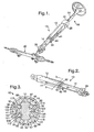
- a shaft assembly 10 including an elongated open-ended tubular outer shaft 12 and an elongated inner shaft 14 extending lengthwise within the outer shaft 12, with the longitudinal center line of the inner shaft coincident with that of the outer shaft.
- a recirculating ball roller joint 16 between the shafts enables relative axial shaft movement.
- FIG. 1 shows the shaft assembly 10 between a steering column 18 and a steering gear 20 of an automotive vehicle.
- the assembly 10 is sometimes referred to as an intermediate shaft.
- the steering column 18 has a steering shaft 22 supported for rotation and axial movement within a tubular jacket 24.
- the front end of the steering shaft 22 is pivoted at 25 to the rear end of the outer shaft 12 of the shaft assembly 10, and the front end of the inner shaft 14 is connected to the steering gear 20 by a universal joint 26.
- the shaft assembly 10 as used in FIG. 1 adjusts for any possible misalignment between the steering column 18 and the steering gear 20.
- the recirculating ball joint 16 includes a shell assembly 28 made up of two shells 30 and 32.
- the shells 30 and 32 are substantially identical so a description of one will suffice for both.
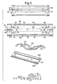
- Each shell has a radially inner cage 34, a radially outer cage 35 and a ball retainer 36 between the inner and outer cages. See FIGS. 3, 4 and 5.
- the inner and outer cages 34 and 35 are assembled together by fitting the outer cage 35 within a recess 37 in the radially outer surface of the inner cage. In this assembled relationship, the two cages are accurately located by locators in the form of pins 38 on the outer cage engaging in holes 39 in the inner cage.
- the radially outer surfaces of the inner and outer cages of both shells 30 and 32 have aligned grooves 40 which receive longitudinally extending radially inwardly offset ridges 41 in the outer shaft 12.
- the shells 30 and 32 are secured to the outer shaft 12 by any suitable means, as by welding or by a suitable adhesive, for example.
- a groove 42 is formed in the inner cage 34. See FIGS. 5 and 6B.
- the groove 42 has a mid-portion 44 that extends lengthwise of the inner cage 34 and at the ends is doubled back or return bent 180° to provide terminal portions 46 and 48 having spaced apart ends 50 and 52 leaving a gap 53 between the ends.
- a groove 54 is formed in the outer cage 35. See FIG. 7B.
- the groove 54 has a mid-portion 56 that extends lengthwise of the outer cage and at the ends is doubled back or return bent 180° to provide terminal portions 58 and 60 having spaced apart ends 62 and 64 leaving a gap 65 between the ends.
- the radially inner cage 34 has a second groove 68. See FIGS. 5 and 6B.
- the groove 68 has a mid-portion 70 that extends lengthwise of the inner cage 34 and at the ends is doubled back or return bent 180° to provide terminal portions 72 and 74 having spaced apart ends 76 and 78 leaving a gap 79 between the ends.
- the outer cage 35 has a groove 80. See FIG. 7B.
- the groove 80 has a mid-portion 82 that extends lengthwise of the outer cage 35 and at the ends is doubled back or return bent 180° to provide terminal portions 84 and 86 having spaced apart ends 88 and 90 leaving a gap 91 between the ends.
- the mid-portions and terminal portions of the grooves 68 and 80 in the inner and outer cages are directly opposed to one another to define a portion only of a second closed circuit ball race 92, also for the recirculation of other balls 67.
- the gap 53 between the ends 50, 52 of the groove 42 of the inner cage 34 and the gap 79 between the ends 76, 78 of the groove 68 of the inner cage 34 are separated by a bar 104 which extends lengthwise of the inner cage.
- the ball retainer 36 has a mid-section which rests upon the bar 104 and curved wings on opposite sides of the mid-section shaped to form grooves 106 and 108 which are disposed respectively in the gap 65 between the ends 62 and 64 of the groove 54 in the outer cage 35 and the gap 91 between the ends 88 and 90 of the groove 80 in the outer cage. See FIG. 3.
- the inner shaft 14 has a pair of longitudinally extending circumferentially spaced apart grooves 110 and 112 on one side separated by a flat surface 114, and a pair of longitudinally extending circumferentially spaced apart grooves 116 and 118 on the opposite side of the inner shaft separated by a second flat surface 120 which is parallel to the flat surface 114.
- the retainer groove 106 of the retainer 36 and the inner shaft groove 110 cooperate to close an open portion of the closed circuit ball race 66 between the groove ends 50, 52 of the groove 42 of the inner cage 34 and the groove ends 62, 64 of the groove 54 of the outer cage 35.
- the retainer groove 108 of the retainer 36 and the inner shaft groove 112 cooperate to close the open portion of the closed circuit ball race 92 between the groove ends 76, 78 of the groove 68 of the inner cage 34 and the groove ends 88, 90 of the groove 80 of the outer cage 35.
- Springs 121 and 122 are provided between the inner and outer cages 34 and 35.
- the springs 121 and 122 press the ball retainer 36 radially inwardly and the ball retainer presses the balls 67 in ball races 66 and 92 radially inwardly through the gaps 53 and 65 and hold them against the inner shaft grooves 110 and 112.
- the retainer grooves 106 and 108 cooperate with the inner shaft grooves 116 and 118 to close the open portion of the closed circuit ball races 66 and 92 in the same manner as described in connection with the shell 30.
- the balls 67 in the ball races 66 and 92 of the two shells 30 and 32 project though the gaps 53 and 65 and have a rolling engagement with the grooves 110, 112, 116, and 118 of the inner shaft 14 to facilitate axial movement of the inner shaft 14 relative to the outer shaft 12.
Landscapes
- Engineering & Computer Science (AREA)
- General Engineering & Computer Science (AREA)
- Mechanical Engineering (AREA)
- Chemical & Material Sciences (AREA)
- Combustion & Propulsion (AREA)
- Transportation (AREA)
- Ocean & Marine Engineering (AREA)
- Steering Controls (AREA)
- Rolling Contact Bearings (AREA)
Applications Claiming Priority (2)
| Application Number | Priority Date | Filing Date | Title |
|---|---|---|---|
| US251228 | 1994-05-31 | ||
| US10/251,228 US6805637B2 (en) | 2002-09-20 | 2002-09-20 | Shaft assembly with recirculating ball roller joint unit |
Publications (3)
| Publication Number | Publication Date |
|---|---|
| EP1400711A2 true EP1400711A2 (de) | 2004-03-24 |
| EP1400711A3 EP1400711A3 (de) | 2006-03-29 |
| EP1400711B1 EP1400711B1 (de) | 2010-05-26 |
Family
ID=31946464
Family Applications (1)
| Application Number | Title | Priority Date | Filing Date |
|---|---|---|---|
| EP03077517A Expired - Lifetime EP1400711B1 (de) | 2002-09-20 | 2003-08-11 | Wellenanordnung mit Kugelumlauflager |
Country Status (3)
| Country | Link |
|---|---|
| US (1) | US6805637B2 (de) |
| EP (1) | EP1400711B1 (de) |
| DE (1) | DE60332695D1 (de) |
Cited By (3)
| Publication number | Priority date | Publication date | Assignee | Title |
|---|---|---|---|---|
| RU2453748C1 (ru) * | 2011-02-25 | 2012-06-20 | Федеральное государственное автономное образовательное учреждение высшего профессионального образования Сибирский федеральный университет (СФУ) | Механическая передача с гибким толкателем |
| KR102208239B1 (ko) * | 2019-07-26 | 2021-01-28 | 남양넥스모 주식회사 | 인터미디어트 샤프트 |
| US11731684B1 (en) * | 2022-02-24 | 2023-08-22 | Steering Solutions Ip Holding Corporation | Recirculating ball track telescope interface assembly for steering column |
Families Citing this family (13)
| Publication number | Priority date | Publication date | Assignee | Title |
|---|---|---|---|---|
| US20050215329A1 (en) * | 2002-10-31 | 2005-09-29 | Matthias Fick | Bearing of a telescopic connection |
| US8021235B2 (en) * | 2008-12-16 | 2011-09-20 | Nexteer (Beijing) Technology Co., Ltd. | Rolling element shaft assembly |
| SE534849C2 (sv) * | 2010-05-03 | 2012-01-17 | Fuji Autotech Ab | Teleskopaxel |
| US9689426B2 (en) | 2010-07-15 | 2017-06-27 | Thomson Industries Inc. | Linear motion bearing with modular bearing segments |
| CN105587767A (zh) | 2010-07-15 | 2016-05-18 | 托马森工业(有限)公司 | 直线运动轴承组件 |
| US9217466B2 (en) * | 2010-07-28 | 2015-12-22 | Thomson Industries, Inc. | Linear motion bearing system with self-aligning rail |
| CN103210222B (zh) * | 2010-08-11 | 2016-05-04 | 托马森工业(有限)公司 | 蛤壳状直线运动轴承组件 |
| US8460116B1 (en) | 2011-12-06 | 2013-06-11 | Dana Automotive Systems Group, Llc | Slip joint and method for assembling the same |
| US8931805B2 (en) * | 2012-11-30 | 2015-01-13 | Steering Solutions Ip Holding Corporation | Telescoping shaft roller assembly in steering column |
| US20150123391A1 (en) * | 2013-11-04 | 2015-05-07 | Readylift Suspension, Inc. | Steering correction and support device and methods of making and using same |
| US9046129B1 (en) * | 2013-11-08 | 2015-06-02 | Ome Technology Co., Ltd. | Linear guideway and circulation module thereof |
| KR101790682B1 (ko) * | 2016-03-16 | 2017-10-26 | 주식회사 드림텍 | 자동차용 유니버설 조인트의 슬라이딩케이지 |
| DE102022109599A1 (de) | 2022-04-21 | 2023-10-26 | Schaeffler Technologies AG & Co. KG | Lageranordnung eines Lenksäulengehäuses eines Kraftfahrzeuges |
Family Cites Families (10)
| Publication number | Priority date | Publication date | Assignee | Title |
|---|---|---|---|---|
| US2791894A (en) * | 1955-12-08 | 1957-05-14 | Gen Motors Corp | Anti-friction joint |
| DE2164543C3 (de) * | 1971-12-24 | 1978-08-24 | Jean Walterscheid Gmbh, 5204 Lohmar | Teleskopwelle |
| JPS5653143Y2 (de) * | 1977-09-06 | 1981-12-11 | ||
| JPS5848775B2 (ja) * | 1981-08-06 | 1983-10-31 | 博 寺町 | 無限摺動用ボ−ルスプライン軸受 |
| US4509386A (en) * | 1982-11-15 | 1985-04-09 | General Motors Corporation | Lash-free telescopic steering shaft assembly and method of making the assembly |
| US5613780A (en) * | 1995-06-29 | 1997-03-25 | Thomson Industries, Inc. | Linear motion bearing assembly |
| US6350203B1 (en) * | 1999-11-18 | 2002-02-26 | Ina Walzlager Schaeffler Ohg | Torque-transmitting linear rolling bearing |
| US6439177B2 (en) | 2000-06-30 | 2002-08-27 | Delphi Technologies, Inc. | Low friction variable valve actuation device |
| US6533369B2 (en) | 2000-10-19 | 2003-03-18 | Delphi Technologies, Inc. | Brake system and method having secondary hydraulic braking in a de-energized operational mode |
| US6582313B2 (en) | 2000-12-22 | 2003-06-24 | Delphi Technologies, Inc. | Constant velocity stroking joint having recirculating spline balls |
-
2002
- 2002-09-20 US US10/251,228 patent/US6805637B2/en not_active Expired - Lifetime
-
2003
- 2003-08-11 DE DE60332695T patent/DE60332695D1/de not_active Expired - Lifetime
- 2003-08-11 EP EP03077517A patent/EP1400711B1/de not_active Expired - Lifetime
Cited By (5)
| Publication number | Priority date | Publication date | Assignee | Title |
|---|---|---|---|---|
| RU2453748C1 (ru) * | 2011-02-25 | 2012-06-20 | Федеральное государственное автономное образовательное учреждение высшего профессионального образования Сибирский федеральный университет (СФУ) | Механическая передача с гибким толкателем |
| EA020260B1 (ru) * | 2011-02-25 | 2014-09-30 | Федеральное Государственное Автономное Образовательное Учреждение Высшего Профессионального Образования "Сибирский Федеральный Университет" | Механическая передача с гибким толкателем |
| KR102208239B1 (ko) * | 2019-07-26 | 2021-01-28 | 남양넥스모 주식회사 | 인터미디어트 샤프트 |
| US11731684B1 (en) * | 2022-02-24 | 2023-08-22 | Steering Solutions Ip Holding Corporation | Recirculating ball track telescope interface assembly for steering column |
| US20230264733A1 (en) * | 2022-02-24 | 2023-08-24 | Steering Solutions Ip Holding Corporation | Recirculating ball track telescope interface assembly for steering column |
Also Published As
| Publication number | Publication date |
|---|---|
| EP1400711A3 (de) | 2006-03-29 |
| DE60332695D1 (de) | 2010-07-08 |
| US6805637B2 (en) | 2004-10-19 |
| EP1400711B1 (de) | 2010-05-26 |
| US20040058738A1 (en) | 2004-03-25 |
Similar Documents
| Publication | Publication Date | Title |
|---|---|---|
| US6805637B2 (en) | Shaft assembly with recirculating ball roller joint unit | |
| US8808097B2 (en) | Fixed type constant velocity universal joint | |
| US20160017929A1 (en) | Propeller Shaft and Adapter Member for Propeller Shaft | |
| US6270418B1 (en) | Elastic shaft joint | |
| US10641316B2 (en) | Bearing sleeve for a shaft | |
| JPS6098216A (ja) | 接触角をもつ軸受を備えた回転支持装置 | |
| EP1394430B2 (de) | Kreuzkupplung | |
| WO2009145034A1 (ja) | 固定型等速自在継手 | |
| EP2896846A2 (de) | Gelenkwellen-Kreuzgelenkkupplungsstruktur | |
| US6364778B1 (en) | Axially adjustable steering shaft assembly with ball spline | |
| US20040197037A1 (en) | Roller bearing for linear movements | |
| CN101346552A (zh) | 等速万向接头及其内侧部件 | |
| EP1908974A1 (de) | Teleskopische welle und lenkvorrichtung für ein fahrzeug | |
| JP3800132B2 (ja) | 車両ステアリング用伸縮軸 | |
| US7163462B2 (en) | Propeller shaft assembly | |
| US9347492B2 (en) | Retainer cap for shaft assembly | |
| EP2128466A1 (de) | Universelles gleichlauffestgelenk | |
| JP2005083532A (ja) | スプライン継手 | |
| CN101466960A (zh) | 滑动式等速万向接头 | |
| KR102745379B1 (ko) | 자동차의 스티어링 시스템의 스티어링 인텀샤프트 | |
| EP1398242A2 (de) | Teleskopische Kupplung mit Wälzlagern | |
| JP2006275102A (ja) | 等速自在継手 | |
| JP2007032645A (ja) | 摺動式等速自在継手 | |
| EP1950437A1 (de) | Universelles gleichlauffestgelenk | |
| JP2008089148A (ja) | 等速自在継手の組立方法 |
Legal Events
| Date | Code | Title | Description |
|---|---|---|---|
| PUAI | Public reference made under article 153(3) epc to a published international application that has entered the european phase |
Free format text: ORIGINAL CODE: 0009012 |
|
| AK | Designated contracting states |
Kind code of ref document: A2 Designated state(s): AT BE BG CH CY CZ DE DK EE ES FI FR GB GR HU IE IT LI LU MC NL PT RO SE SI SK TR |
|
| AX | Request for extension of the european patent |
Extension state: AL LT LV MK |
|
| PUAL | Search report despatched |
Free format text: ORIGINAL CODE: 0009013 |
|
| AK | Designated contracting states |
Kind code of ref document: A3 Designated state(s): AT BE BG CH CY CZ DE DK EE ES FI FR GB GR HU IE IT LI LU MC NL PT RO SE SI SK TR |
|
| AX | Request for extension of the european patent |
Extension state: AL LT LV MK |
|
| 17P | Request for examination filed |
Effective date: 20060929 |
|
| AKX | Designation fees paid |
Designated state(s): DE FR GB IT |
|
| 17Q | First examination report despatched |
Effective date: 20061228 |
|
| GRAP | Despatch of communication of intention to grant a patent |
Free format text: ORIGINAL CODE: EPIDOSNIGR1 |
|
| GRAS | Grant fee paid |
Free format text: ORIGINAL CODE: EPIDOSNIGR3 |
|
| GRAA | (expected) grant |
Free format text: ORIGINAL CODE: 0009210 |
|
| AK | Designated contracting states |
Kind code of ref document: B1 Designated state(s): DE FR GB IT |
|
| REG | Reference to a national code |
Ref country code: GB Ref legal event code: FG4D |
|
| REF | Corresponds to: |
Ref document number: 60332695 Country of ref document: DE Date of ref document: 20100708 Kind code of ref document: P |
|
| REG | Reference to a national code |
Ref country code: FR Ref legal event code: TP |
|
| RAP2 | Party data changed (patent owner data changed or rights of a patent transferred) |
Owner name: GM GLOBAL TECHNOLOGY OPERATIONS, INC. |
|
| PG25 | Lapsed in a contracting state [announced via postgrant information from national office to epo] |
Ref country code: IT Free format text: LAPSE BECAUSE OF FAILURE TO SUBMIT A TRANSLATION OF THE DESCRIPTION OR TO PAY THE FEE WITHIN THE PRESCRIBED TIME-LIMIT Effective date: 20100526 |
|
| PLBE | No opposition filed within time limit |
Free format text: ORIGINAL CODE: 0009261 |
|
| STAA | Information on the status of an ep patent application or granted ep patent |
Free format text: STATUS: NO OPPOSITION FILED WITHIN TIME LIMIT |
|
| GBPC | Gb: european patent ceased through non-payment of renewal fee |
Effective date: 20100826 |
|
| 26N | No opposition filed |
Effective date: 20110301 |
|
| REG | Reference to a national code |
Ref country code: FR Ref legal event code: ST Effective date: 20110502 |
|
| REG | Reference to a national code |
Ref country code: DE Ref legal event code: R081 Ref document number: 60332695 Country of ref document: DE Owner name: STEERING SOLUTIONS IP HOLDING CORP., SAGINAW, US Free format text: FORMER OWNER: DELPHI TECHNOLOGIES, INC., TROY, MICH., US Effective date: 20110412 Ref country code: DE Ref legal event code: R081 Ref document number: 60332695 Country of ref document: DE Owner name: GM GLOBAL TECHNOLOGY OPERATIONS LLC (N. D. GES, US Free format text: FORMER OWNER: DELPHI TECHNOLOGIES, INC., TROY, MICH., US Effective date: 20110412 Ref country code: DE Ref legal event code: R097 Ref document number: 60332695 Country of ref document: DE Effective date: 20110228 |
|
| PG25 | Lapsed in a contracting state [announced via postgrant information from national office to epo] |
Ref country code: FR Free format text: LAPSE BECAUSE OF NON-PAYMENT OF DUE FEES Effective date: 20100831 |
|
| PG25 | Lapsed in a contracting state [announced via postgrant information from national office to epo] |
Ref country code: GB Free format text: LAPSE BECAUSE OF NON-PAYMENT OF DUE FEES Effective date: 20100826 |
|
| REG | Reference to a national code |
Ref country code: DE Ref legal event code: R082 Ref document number: 60332695 Country of ref document: DE Representative=s name: MANITZ, FINSTERWALD & PARTNER GBR, DE |
|
| REG | Reference to a national code |
Ref country code: DE Ref legal event code: R082 Ref document number: 60332695 Country of ref document: DE Representative=s name: MANITZ, FINSTERWALD & PARTNER GBR, DE Effective date: 20121019 Ref country code: DE Ref legal event code: R081 Ref document number: 60332695 Country of ref document: DE Owner name: STEERING SOLUTIONS IP HOLDING CORP., US Free format text: FORMER OWNER: GM GLOBAL TECHNOLOGY OPERATIONS, INC., DETROIT, US Effective date: 20121019 Ref country code: DE Ref legal event code: R081 Ref document number: 60332695 Country of ref document: DE Owner name: GM GLOBAL TECHNOLOGY OPERATIONS LLC (N. D. GES, US Free format text: FORMER OWNER: GM GLOBAL TECHNOLOGY OPERATIONS, INC., DETROIT, US Effective date: 20121019 Ref country code: DE Ref legal event code: R081 Ref document number: 60332695 Country of ref document: DE Owner name: STEERING SOLUTIONS IP HOLDING CORP., SAGINAW, US Free format text: FORMER OWNER: GM GLOBAL TECHNOLOGY OPERATIONS, INC., DETROIT, MICH., US Effective date: 20121019 Ref country code: DE Ref legal event code: R081 Ref document number: 60332695 Country of ref document: DE Owner name: GM GLOBAL TECHNOLOGY OPERATIONS LLC (N. D. GES, US Free format text: FORMER OWNER: GM GLOBAL TECHNOLOGY OPERATIONS, INC., DETROIT, MICH., US Effective date: 20121019 |
|
| REG | Reference to a national code |
Ref country code: DE Ref legal event code: R082 Ref document number: 60332695 Country of ref document: DE Representative=s name: MANITZ, FINSTERWALD & PARTNER GBR, DE |
|
| REG | Reference to a national code |
Ref country code: DE Ref legal event code: R081 Ref document number: 60332695 Country of ref document: DE Owner name: GM GLOBAL TECHNOLOGY OPERATIONS LLC (N. D. GES, US Free format text: FORMER OWNER: GM GLOBAL TECHNOLOGY OPERATIONS LLC (N. D. GES. D. STAATES DELAWARE), DETROIT, US Effective date: 20130313 Ref country code: DE Ref legal event code: R081 Ref document number: 60332695 Country of ref document: DE Owner name: STEERING SOLUTIONS IP HOLDING CORP., US Free format text: FORMER OWNER: GM GLOBAL TECHNOLOGY OPERATIONS LLC (N. D. GES. D. STAATES DELAWARE), DETROIT, US Effective date: 20130313 Ref country code: DE Ref legal event code: R082 Ref document number: 60332695 Country of ref document: DE Representative=s name: MANITZ, FINSTERWALD & PARTNER GBR, DE Effective date: 20130313 Ref country code: DE Ref legal event code: R081 Ref document number: 60332695 Country of ref document: DE Owner name: GM GLOBAL TECHNOLOGY OPERATIONS LLC (N. D. GES, US Free format text: FORMER OWNER: GM GLOBAL TECHNOLOGY OPERATIONS LLC (N. D. GES. D. STAATES DELAWARE), DETROIT, MICH., US Effective date: 20130313 Ref country code: DE Ref legal event code: R081 Ref document number: 60332695 Country of ref document: DE Owner name: STEERING SOLUTIONS IP HOLDING CORP., SAGINAW, US Free format text: FORMER OWNER: GM GLOBAL TECHNOLOGY OPERATIONS LLC (N. D. GES. D. STAATES DELAWARE), DETROIT, MICH., US Effective date: 20130313 |
|
| PGFP | Annual fee paid to national office [announced via postgrant information from national office to epo] |
Ref country code: DE Payment date: 20130828 Year of fee payment: 11 |
|
| REG | Reference to a national code |
Ref country code: DE Ref legal event code: R119 Ref document number: 60332695 Country of ref document: DE |
|
| REG | Reference to a national code |
Ref country code: DE Ref legal event code: R119 Ref document number: 60332695 Country of ref document: DE Effective date: 20150303 |
|
| PG25 | Lapsed in a contracting state [announced via postgrant information from national office to epo] |
Ref country code: DE Free format text: LAPSE BECAUSE OF NON-PAYMENT OF DUE FEES Effective date: 20150303 |