EP1400740B1 - Dispositif de fixation d'un tuyau flexible - Google Patents
Dispositif de fixation d'un tuyau flexible Download PDFInfo
- Publication number
- EP1400740B1 EP1400740B1 EP03020533A EP03020533A EP1400740B1 EP 1400740 B1 EP1400740 B1 EP 1400740B1 EP 03020533 A EP03020533 A EP 03020533A EP 03020533 A EP03020533 A EP 03020533A EP 1400740 B1 EP1400740 B1 EP 1400740B1
- Authority
- EP
- European Patent Office
- Prior art keywords
- holding
- hose
- tube
- region
- area
- Prior art date
- Legal status (The legal status is an assumption and is not a legal conclusion. Google has not performed a legal analysis and makes no representation as to the accuracy of the status listed.)
- Expired - Lifetime
Links
- 230000014759 maintenance of location Effects 0.000 claims description 3
- 238000005452 bending Methods 0.000 description 10
- 230000001681 protective effect Effects 0.000 description 9
- 230000015572 biosynthetic process Effects 0.000 description 8
- 238000005755 formation reaction Methods 0.000 description 8
- 230000007704 transition Effects 0.000 description 4
- 239000011324 bead Substances 0.000 description 2
- 230000000295 complement effect Effects 0.000 description 2
- 210000002816 gill Anatomy 0.000 description 1
- 239000000463 material Substances 0.000 description 1
- 239000007787 solid Substances 0.000 description 1
Images



Classifications
-
- F—MECHANICAL ENGINEERING; LIGHTING; HEATING; WEAPONS; BLASTING
- F16—ENGINEERING ELEMENTS AND UNITS; GENERAL MEASURES FOR PRODUCING AND MAINTAINING EFFECTIVE FUNCTIONING OF MACHINES OR INSTALLATIONS; THERMAL INSULATION IN GENERAL
- F16L—PIPES; JOINTS OR FITTINGS FOR PIPES; SUPPORTS FOR PIPES, CABLES OR PROTECTIVE TUBING; MEANS FOR THERMAL INSULATION IN GENERAL
- F16L25/00—Construction or details of pipe joints not provided for in, or of interest apart from, groups F16L13/00 - F16L23/00
- F16L25/0036—Joints for corrugated pipes
-
- H—ELECTRICITY
- H02—GENERATION; CONVERSION OR DISTRIBUTION OF ELECTRIC POWER
- H02G—INSTALLATION OF ELECTRIC CABLES OR LINES, OR OF COMBINED OPTICAL AND ELECTRIC CABLES OR LINES
- H02G3/00—Installations of electric cables or lines or protective tubing therefor in or on buildings, equivalent structures or vehicles
- H02G3/02—Details
- H02G3/06—Joints for connecting lengths of protective tubing or channels, to each other or to casings, e.g. to distribution boxes; Ensuring electrical continuity in the joint
- H02G3/0616—Joints for connecting tubing to casing
- H02G3/0691—Fixing tubing to casing by auxiliary means co-operating with indentations of the tubing, e.g. with tubing-convolutions
Definitions
- the invention relates to a device for holding a flexible hose.
- Machines and in particular industrial robots have flexible protective hoses through which supply lines, cables or the like, referred to collectively as hose packages, are guided for devices of the machine or of the robot, in particular of the tool attached to a robot hand, which are to be held together and protected by the protective hose ,
- the flexible hose may in part be subjected to extreme sideways or turning movements, for example when the tools (cables) terminating at the tool (s) are subjected to various relative movements by the tool movement which the hose surrounding them has to follow.
- hose at its end facing away from the tool-side end of the supply lines and cables is fixed to a locking point of the machine or the robot, the lateral or bending movements of the protective hose can lead to fatigue and eventually breakage and damage to the protective hose.
- ball joints are provided for holding the protective tube on the end facing away from the tool. These have only a small range of mobility and can load other elements of the hose packages when unloaded (in the axial direction). They are also expensive and expensive.
- FR-1 286 787 discloses a device according to the preamble of claim 1
- the invention is therefore an object of the invention to provide a simple and inexpensive relief aid for a flexible hose, which nevertheless ensures good support of a flexible hose with lateral movement or bending with relatively large mobility and thus enabling a tight bending radius and thus wear loads of Hose reduced, without further hose package components are excessively loaded.
- the invention is defined by the features of claim 1.
- the tube at least axially holding device has at least one side a support area with preferably trumpet-like extension
- the hose is supported in lateral or bending movements and thus relieved; he can not bend in this area.
- the radius R1 of the extension is at least in the inner region of the same order of magnitude of the minimum bending radius of the male tube minus (-) half the diameter of the tube.
- the minimum bending radius of a hose can usually be found in the hose manufacturer's table. Alternatively, it can also be determined by site tests.
- the extension knows immediately before its front end or at this radius R2 on which is smaller than the radius R1 and preferably 10% to 20% of the radius of the inner extension region .
- a first rib for holding a ribbed tube and the inner extension region is preferably a cylindrical portion. The transitions from the cylindrical section to the inner extension region with radius R1 and from there to the rounding with radius R2 in the region of the front end are each tangential and therefore continuous.
- a preferred embodiment of the invention provides that the holding region has inwardly directed annular ribs. In this way, a positive retention of the protective tube in the device according to the invention is achieved in the axial direction, while, if desired, against frictional or frictional connection between the device and the hose according to the invention can be effected by appropriate dimensioning.
- a mounting region for attachment of the device is provided on a holding part, wherein the holding part is preferably formed as a clamp.
- the invention further provides that the mounting region has an outer annular groove, wherein in the annular groove inwardly directed lugs of the holding part or the clamp engage, so that here also an axially positive connection between the holding part / clamp and inventive device is ensured.
- the device of the invention can be placed on the hose, the invention provides in a further preferred embodiment that an education from at least two partial shells (half shells) is provided.
- the individual partial or half shells of the device according to the invention can be held together radially in various known manner, for example by screwing or by snap connections on their end faces.
- the partial shells can be held together by a closing ring, which can be formed in one piece and is then pushed axially onto a cylindrical holding portion of the device according to the invention.
- the closing ring can also be designed in several parts, with connecting devices being formed on its end faces.
- the partial rings of the locking ring can be connected to each other by means of snap formations by snapping perpendicular to the axis of symmetry, wherein in the closed position engaging behind, complementary formations on the faces of the partial rings of the locking ring and axial connectivity of the formations and thus partial rings are provided.
- a locking ring is in the EP 1 400 710 disclosed.
- a device for holding a hose which protects it against damage by the axial support when bending the hose this applies to the inner radius of the extension of the support area and thus supported by this and relieved.
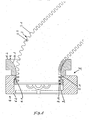
- the inventive device 1 is used in the illustrated embodiment for holding a finned tube 2.
- a finned tube 2 is provided at least on its outside with ribs 2.1, between which annular grooves 2.2 are formed.
- the device 1 For axial retention of the fin tube 2, the device 1 according to the invention has an inner holding region 3, on which inwardly projecting annular ribs 3.1 are formed are.
- annular ribs 3.1 In the illustrated embodiment, two annular ribs are provided. But it can also be provided an annular rib or more than two annular ribs.
- the annular ribs 3.1 point into the annular grooves 2.2 of the ribbed tube 2 and thereby hold it axially fixed.
- a security against rotation can be given by a frictional connection.
- the rib hose 2 protrudes in the representation of the figures at least to the right out of the device 1.
- a support region 4 of the device 1 adjoins the holding region 3 in the direction of the region of the finned tube 2 protruding from the device 1, ie into the Drawings also shown to the right seen from the holding area 3 from.
- a lateral or bending movement of the finned tube 2, as in the FIG. 1 can occur, for example, when the finned tube 2 serves as a protective tube for supply lines or cables of motors or a tool on a robot hand, the latter can perform multiple movements (usually around three axes), which the supply lines or cables and thus also have to follow the free end of the finned tube 2.
- the support region 4 of the device 1 according to the invention has a trumpet-like extension 4.1.
- the widening 4.1 is thus continuous, continuous and, if appropriate, formed with a progressively reducing radius of curvature from the holding region 3 at the free end 4.2 of the support region 4.
- the device 1 according to the invention is further formed with a mounting region 5, via which it can be attached or fixed to a robot part.
- the attachment region 5 has an outer annular groove 5.1, which engages in an inner annular projection 6.1 of a mounting clamp 6 and thus the device 1 - and the rib hose 2 - axially on a machine, to a robot or the like, to which the clamp 6 attached is.
- the holder of the device 1 in the clamp 6 is rotatable, so that the device 1 can rotate with this in the clamp 6 during rotational movements of the finned tube 2.
- the clamp 6 may have a further inner annular shoulder 6.2, over which an end piece of another ribbed hose or the like can be fixed.
- the mounting portion 5 is formed substantially at the same shaft height, radially outside of the inner holding portion 3; but between the areas 3 and 5 can also be an axial offset.
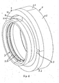
- the attachment region 5, holding region 3 and support region 4 are integrally formed, wherein, however, the entire device is divided in the circumferential direction, ie formed of a plurality of parts, preferably two partial shells (half shells), as in particular the FIGS. 4 and 6 is removable.
- the two half-shells can then be held together in a manner known per se, for example by screws (as shown in FIG FIG. 6 is shown) by acting in the circumferential direction snap closures, either in the Half shells themselves or are formed on an additional locking ring.
- FIG. 4 shows a further possibility for holding together the half-shells 1.1, 1.2 of the device 1 according to the invention, namely by a locking ring 7, consisting of two half-rings 7.1 and 7.2, which have circumferentially acting, mutually complementary relatively rigid or solid formations 7.3 on their faces, by means of which closed the locking ring 7 and thus also holds the existing of the two half-shells 1.1 and 1.2 device 1.
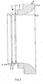
- the locking ring 7 is seated on an annular shoulder 8 of the device 1 (this also FIG. 2 ) preferably by friction.
- the connection of the two halves 7.1 and 7.2 of the locking ring 7 takes place in that the formations 7.3 are inserted into each other in the axial direction.
- the half-shells 1.1, 1.2 of the device 1 according to the invention for preventing relative axial movement between them form on education, which in the illustration of FIG. 3 are formed as pins 1.3 and holes 1.4.
- the contact areas of the half-shells 1.1, 1.2 and ribs 2.1 and 2.2 grooves can be provided.
- FIGS. 1 to 4 show a somewhat modified embodiment of the device according to the invention for holding a ribbed tube. As far as the same parts are present, they are provided with the same reference numerals and the description is based on the description of the embodiment of FIGS. 1 to 4 referred, so that in the following essentially only the different embodiments will be described.
- the device 1 according to the invention also has a holding region 3 for a ribbed tube 2, wherein the holding region 3 likewise has two inwardly projecting annular ribs 3.1.
- a support region 4 continues to connect - a device according to the invention can also have two support regions which extend on both sides from the holding section 3 and which expand on the inside toward the outside.
- attachment region 5 with an annular groove 5.1, which in the embodiment of Figures 5 and 6 is arranged axially offset relative to the inner holding portion 3, in the opposite direction to the support area. 4
- inventions 9.1 and 9.2 which are formed substantially by close to the parting surface of the half-shells 1.1, 1.2 of the device 1 in an outer annular bead 9.3, 9.4 formed openings 9.5, 9.6 through which the finned tube 2 for holding the half-shells 1.1 and 1.2 of the device 1 according to the invention can be pushed through, which can be determined by either cutting the screw thread in the plastic material of the device 1 either with appropriate formation of the breakthroughs in each case or by a provided on the opposite side connectable with the screw nut.
- the support portion 4 is formed elongated than in the embodiment of FIGS. 1 to 4 and the curvature ratios, also in principle progressively larger in the form of the region 3 to the free end side reducing radius of curvature are so from the curvature of the trumpet-like expanding area so not as strong as in the embodiment of the FIGS. 1 to 4 ,
- FIG. 7 shows a further longitudinal sectional view of a device according to the invention similar to that of FIG. 5 , That too FIG. 7
- the trumpet-like extension 4.1 initially a cylindrical portion 5.2, the diameter of which corresponds substantially to the outer diameter of the fin tube.
- the actual or inner extension area 4.1 This has a radius of curvature of the extension R1, which corresponds to the minimum bending radius of the tube minus half the diameter of the male tube.
- the minimum bending radius of the hose is usually specified by the hose manufacturer; alternatively, it can be determined from experiments.
- transitions between the cylindrical section 4.5 and the extension or support region 4.1 and between these and the outer rounding are each tangential and thus continuous.
Landscapes
- Engineering & Computer Science (AREA)
- General Engineering & Computer Science (AREA)
- Mechanical Engineering (AREA)
- Architecture (AREA)
- Civil Engineering (AREA)
- Structural Engineering (AREA)
- Supports For Pipes And Cables (AREA)
- Protection Of Pipes Against Damage, Friction, And Corrosion (AREA)
Claims (4)
- Pièce de retenue (6) et dispositif (1) pour retenir un tuyau flexible(2), avec au moins une zone de retenue (3) pour retenir le tuyau flexible (2) au moins dans le sens axial et avec au moins une zone soutènement (4) unilatérale, s'élargissant vers son extrémité libre (4.2) et enveloppant le tuyau flexible (2), ledit dispositif présentant une zone d'attache (5) pour attacher ce dernier à la pièce de retenue (6), de laquelle un téton (6.1) de la pièce de retenue (6), tourné vers l'intérieur, prend prise de manière à fixer le dispositif (1) dans le sens axial, mais de façon néanmoins mobile à la pièce de retenue (6).
- Dispositif selon la revendication 1, caractérisé en ce que la zone de retenue (3) présente des nervures annulaires (3.1) tournées vers l'intérieur.
- Dispositif selon une des revendications 1 ou 2,
caractérisé en ce que la pièce de retenue (6) est formée par un collier de fixation. - Dispositif selon une des revendications 1 à 3,
caractérisé en ce que la zone de soutènement présente un élargissement en forme de trompette (4.1).
Applications Claiming Priority (2)
| Application Number | Priority Date | Filing Date | Title |
|---|---|---|---|
| DE10244027A DE10244027A1 (de) | 2002-09-21 | 2002-09-21 | Vorrichtung zum Halten eines Schlauches |
| DE10244027 | 2002-09-21 |
Publications (3)
| Publication Number | Publication Date |
|---|---|
| EP1400740A2 EP1400740A2 (fr) | 2004-03-24 |
| EP1400740A3 EP1400740A3 (fr) | 2004-05-12 |
| EP1400740B1 true EP1400740B1 (fr) | 2008-08-13 |
Family
ID=31896279
Family Applications (1)
| Application Number | Title | Priority Date | Filing Date |
|---|---|---|---|
| EP03020533A Expired - Lifetime EP1400740B1 (fr) | 2002-09-21 | 2003-09-17 | Dispositif de fixation d'un tuyau flexible |
Country Status (3)
| Country | Link |
|---|---|
| US (1) | US20040070203A1 (fr) |
| EP (1) | EP1400740B1 (fr) |
| DE (2) | DE10244027A1 (fr) |
Cited By (1)
| Publication number | Priority date | Publication date | Assignee | Title |
|---|---|---|---|---|
| DE102022119299A1 (de) | 2022-08-02 | 2024-02-08 | Kuka Deutschland Gmbh | Leitungsprotektorring |
Families Citing this family (2)
| Publication number | Priority date | Publication date | Assignee | Title |
|---|---|---|---|---|
| JP4261598B2 (ja) | 2007-07-30 | 2009-04-30 | ファナック株式会社 | 産業用ロボットの線条体処理構造 |
| CN109895139B (zh) * | 2019-04-30 | 2024-04-23 | 上海方鑫材料科技有限公司 | 一种机械手臂关节部位穿线固定件 |
Family Cites Families (21)
| Publication number | Priority date | Publication date | Assignee | Title |
|---|---|---|---|---|
| US2122988A (en) * | 1935-05-22 | 1938-07-05 | Westinghouse X Ray Co Inc | Shockproof x-ray tube stand |
| US2514059A (en) * | 1944-05-18 | 1950-07-04 | Bristol Company | Coupling device |
| US2431154A (en) * | 1946-03-28 | 1947-11-18 | Bay Shore Machine Company Inc | Cable securing device |
| US2547263A (en) * | 1946-07-03 | 1951-04-03 | Waldes Kohinoor Inc | Retaining ring |
| FR1286787A (fr) * | 1961-01-24 | 1962-03-09 | Manuf De Caoutchouc Et D Eboni | Raccord pour tuyaux métalliques souples spiralés |
| US3498642A (en) * | 1967-11-06 | 1970-03-03 | Schurz Controls Corp | Pipe fitting |
| US3464307A (en) * | 1968-04-29 | 1969-09-02 | Waldes Kohinoor Inc | Retaining rings |
| US3588150A (en) * | 1969-07-18 | 1971-06-28 | Raychem Corp | Attaching device for convoluted tubing |
| US3934902A (en) * | 1973-12-18 | 1976-01-27 | Rca Corporation | Connector for a corrugated conduit |
| JPH0342302Y2 (fr) * | 1987-11-10 | 1991-09-04 | ||
| FR2642814B1 (fr) * | 1989-02-08 | 1991-05-10 | Labinal | Bague de fermeture de gaines annelees |
| IT1250869B (it) * | 1991-12-06 | 1995-04-21 | Rachetto S P A | Dispositivo di connessione rapida a tenuta,per tubi flessibili metallici non trecciati. |
| US6056245A (en) * | 1996-01-25 | 2000-05-02 | Phillip E. White | Flared cable support for telecommunication system installations |
| DE19630152C1 (de) * | 1996-07-25 | 1997-05-15 | Gloeckler Dichtsysteme Guenter | Formschlüssige Verbindung |
| US5984375A (en) * | 1997-07-23 | 1999-11-16 | Schlumberger Industries, Inc. | Hose collar and method of use therefor |
| DE29814416U1 (de) * | 1998-08-11 | 1998-10-08 | Kuka Roboter GmbH, 86165 Augsburg | Endstück für einen Roboter-Schutzschlauch |
| US6099046A (en) * | 1998-10-21 | 2000-08-08 | Seung-Il Oh | Connector for metal ribbed pipe |
| DE19851885C2 (de) * | 1998-11-11 | 2002-06-20 | Ernst & Engbring Gmbh & Co Kg | Halterung für einen Kabelstrang |
| DE20010696U1 (de) * | 2000-06-15 | 2001-07-26 | Kuka Roboter GmbH, 86165 Augsburg | Vorrichtung zum Festlegen von Kabeln eines Kabelführungsschlauchs |
| JP4092086B2 (ja) * | 2000-06-30 | 2008-05-28 | 矢崎総業株式会社 | コルゲートチューブ固定具 |
| DE20100947U1 (de) * | 2001-01-19 | 2001-05-03 | Kuka Roboter GmbH, 86165 Augsburg | Verschleißring |
-
2002
- 2002-09-21 DE DE10244027A patent/DE10244027A1/de not_active Ceased
-
2003
- 2003-09-17 DE DE50310310T patent/DE50310310D1/de not_active Expired - Lifetime
- 2003-09-17 EP EP03020533A patent/EP1400740B1/fr not_active Expired - Lifetime
- 2003-09-18 US US10/664,716 patent/US20040070203A1/en not_active Abandoned
Cited By (1)
| Publication number | Priority date | Publication date | Assignee | Title |
|---|---|---|---|---|
| DE102022119299A1 (de) | 2022-08-02 | 2024-02-08 | Kuka Deutschland Gmbh | Leitungsprotektorring |
Also Published As
| Publication number | Publication date |
|---|---|
| DE50310310D1 (de) | 2008-09-25 |
| DE10244027A1 (de) | 2004-04-08 |
| EP1400740A2 (fr) | 2004-03-24 |
| US20040070203A1 (en) | 2004-04-15 |
| EP1400740A3 (fr) | 2004-05-12 |
Similar Documents
| Publication | Publication Date | Title |
|---|---|---|
| DE4341140C2 (de) | Ratschenschraubenschlüsselanordnung zum Antreiben eines Befestigungselements | |
| DE69716147T2 (de) | Vorrichtung zum Anbringen von Klemmringen | |
| DE102012105151B3 (de) | Gleitlager für eine Lenkspindel | |
| DE102010027445B3 (de) | Vorichtung zur Fixierung eines Kabels an einen Kabelabgangsstutzen | |
| DE69324685T2 (de) | Einstellbare greifvorrichtung | |
| EP1163986A2 (fr) | Dispositif de fixation d'un tuyau de guidage de câbles | |
| DE19713211A1 (de) | Lagervorrichtung für eine Achse | |
| DE102006048828A1 (de) | Haltebuchse für eine Befestigungsvorrichtung | |
| DE102016109048A1 (de) | Aufnahmevorrichtung und Kabelbaum | |
| DE102020102826A1 (de) | Seilhalter und Steuersatz mit diesem Seilhalter | |
| DE102007039858B4 (de) | Kugelgelenk | |
| DE69828344T2 (de) | Schutzhülle für ein Kugelgelenk | |
| DE602005003046T2 (de) | Befestigungsmutter mit unterstützter Funktion zum Lösen | |
| DE2717936A1 (de) | Gelenkwelle | |
| DE202007012036U1 (de) | Verschleißring (Protektor) | |
| DE69421131T2 (de) | Schraubenschlüssel | |
| DE102016211905A1 (de) | System zur spanenden Bearbeitung eines Bauteils sowie Bauteil und Spannelement für das System | |
| EP4011802A1 (fr) | Dispositif de protection contre l'abrasion pour tubes, tuyaux ou câbles flexibles le long des pièces de machine en mouvement | |
| EP1398552A1 (fr) | Support pivotant pour un tuyau | |
| EP4103856B1 (fr) | Ensemble palier | |
| DE20114345U1 (de) | Vorrichtung zum Halten von Versorgungsleitungen an einem mehrachsigen Industrieroboter | |
| EP1400740A2 (fr) | Dispositif de fixation d'un tuyau flexible | |
| DE4110311C2 (fr) | ||
| DE10153822C1 (de) | Schutzanordnung für ein Gelenk, insbesondere Doppelkreuzgelenk | |
| DE102010027444B3 (de) | Kabelzugentlastung und Dichtungssystem |
Legal Events
| Date | Code | Title | Description |
|---|---|---|---|
| PUAI | Public reference made under article 153(3) epc to a published international application that has entered the european phase |
Free format text: ORIGINAL CODE: 0009012 |
|
| AK | Designated contracting states |
Kind code of ref document: A2 Designated state(s): AT BE BG CH CY CZ DE DK EE ES FI FR GB GR HU IE IT LI LU MC NL PT RO SE SI SK TR |
|
| AX | Request for extension of the european patent |
Extension state: AL LT LV MK |
|
| PUAL | Search report despatched |
Free format text: ORIGINAL CODE: 0009013 |
|
| AK | Designated contracting states |
Kind code of ref document: A3 Designated state(s): AT BE BG CH CY CZ DE DK EE ES FI FR GB GR HU IE IT LI LU MC NL PT RO SE SI SK TR |
|
| AX | Request for extension of the european patent |
Extension state: AL LT LV MK |
|
| RIC1 | Information provided on ipc code assigned before grant |
Ipc: 7F 16L 25/00 A Ipc: 7H 02G 3/06 B |
|
| 17P | Request for examination filed |
Effective date: 20040728 |
|
| AKX | Designation fees paid |
Designated state(s): DE FR GB IT SE |
|
| 17Q | First examination report despatched |
Effective date: 20070122 |
|
| GRAP | Despatch of communication of intention to grant a patent |
Free format text: ORIGINAL CODE: EPIDOSNIGR1 |
|
| GRAS | Grant fee paid |
Free format text: ORIGINAL CODE: EPIDOSNIGR3 |
|
| GRAA | (expected) grant |
Free format text: ORIGINAL CODE: 0009210 |
|
| RAP1 | Party data changed (applicant data changed or rights of an application transferred) |
Owner name: KUKA ROBOTER GMBH |
|
| AK | Designated contracting states |
Kind code of ref document: B1 Designated state(s): DE FR GB IT SE |
|
| REG | Reference to a national code |
Ref country code: GB Ref legal event code: FG4D Free format text: NOT ENGLISH |
|
| REF | Corresponds to: |
Ref document number: 50310310 Country of ref document: DE Date of ref document: 20080925 Kind code of ref document: P |
|
| REG | Reference to a national code |
Ref country code: SE Ref legal event code: TRGR |
|
| PLBE | No opposition filed within time limit |
Free format text: ORIGINAL CODE: 0009261 |
|
| STAA | Information on the status of an ep patent application or granted ep patent |
Free format text: STATUS: NO OPPOSITION FILED WITHIN TIME LIMIT |
|
| 26N | No opposition filed |
Effective date: 20090514 |
|
| GBPC | Gb: european patent ceased through non-payment of renewal fee |
Effective date: 20081113 |
|
| PG25 | Lapsed in a contracting state [announced via postgrant information from national office to epo] |
Ref country code: IT Free format text: LAPSE BECAUSE OF FAILURE TO SUBMIT A TRANSLATION OF THE DESCRIPTION OR TO PAY THE FEE WITHIN THE PRESCRIBED TIME-LIMIT Effective date: 20080813 |
|
| REG | Reference to a national code |
Ref country code: FR Ref legal event code: ST Effective date: 20090731 |
|
| PG25 | Lapsed in a contracting state [announced via postgrant information from national office to epo] |
Ref country code: GB Free format text: LAPSE BECAUSE OF NON-PAYMENT OF DUE FEES Effective date: 20081113 |
|
| PG25 | Lapsed in a contracting state [announced via postgrant information from national office to epo] |
Ref country code: FR Free format text: LAPSE BECAUSE OF NON-PAYMENT OF DUE FEES Effective date: 20081013 |
|
| REG | Reference to a national code |
Ref country code: DE Ref legal event code: R082 Ref document number: 50310310 Country of ref document: DE |
|
| REG | Reference to a national code |
Ref country code: DE Ref legal event code: R081 Ref document number: 50310310 Country of ref document: DE Owner name: KUKA DEUTSCHLAND GMBH, DE Free format text: FORMER OWNER: KUKA ROBOTER GMBH, 86165 AUGSBURG, DE |
|
| PGFP | Annual fee paid to national office [announced via postgrant information from national office to epo] |
Ref country code: SE Payment date: 20220714 Year of fee payment: 20 Ref country code: DE Payment date: 20220609 Year of fee payment: 20 |
|
| P01 | Opt-out of the competence of the unified patent court (upc) registered |
Effective date: 20230528 |
|
| REG | Reference to a national code |
Ref country code: DE Ref legal event code: R071 Ref document number: 50310310 Country of ref document: DE |
|
| REG | Reference to a national code |
Ref country code: SE Ref legal event code: EUG |