EP1400764B1 - Installation de préparation d'eau chaude - Google Patents
Installation de préparation d'eau chaude Download PDFInfo
- Publication number
- EP1400764B1 EP1400764B1 EP02020946A EP02020946A EP1400764B1 EP 1400764 B1 EP1400764 B1 EP 1400764B1 EP 02020946 A EP02020946 A EP 02020946A EP 02020946 A EP02020946 A EP 02020946A EP 1400764 B1 EP1400764 B1 EP 1400764B1
- Authority
- EP
- European Patent Office
- Prior art keywords
- heating circuit
- water
- heat exchanger
- circuit
- heat
- Prior art date
- Legal status (The legal status is an assumption and is not a legal conclusion. Google has not performed a legal analysis and makes no representation as to the accuracy of the status listed.)
- Expired - Lifetime
Links
Images
Classifications
-
- B—PERFORMING OPERATIONS; TRANSPORTING
- B60—VEHICLES IN GENERAL
- B60H—ARRANGEMENTS OF HEATING, COOLING, VENTILATING OR OTHER AIR-TREATING DEVICES SPECIALLY ADAPTED FOR PASSENGER OR GOODS SPACES OF VEHICLES
- B60H1/00—Heating, cooling or ventilating devices
- B60H1/00357—Air-conditioning arrangements specially adapted for particular vehicles
- B60H1/00364—Air-conditioning arrangements specially adapted for particular vehicles for caravans or trailers
-
- B—PERFORMING OPERATIONS; TRANSPORTING
- B60—VEHICLES IN GENERAL
- B60R—VEHICLES, VEHICLE FITTINGS, OR VEHICLE PARTS, NOT OTHERWISE PROVIDED FOR
- B60R15/00—Arrangements or adaptations of sanitation devices
Definitions
- the present invention relates to a system for water heating in land and water vehicles, such as campers, caravans, boats u. Like .. according to the preamble of claim 1.
- the present invention has for its object to provide a system for water heating in land and water vehicles, such as campers, caravans, boats u. Like., To create that can be operated largely gas and electricity.
- the solution according to the invention consists in the idea of using three heat sources for hot water preparation of the corresponding vehicles, namely the waste heat of a refrigerator of the vehicle, the waste heat of the drive motor of the vehicle and the heat generated by a solar collector.
- the combination of these three heat sources ensures a high degree of independence from conventional energy sources, such as gas or electricity, so that the above-mentioned disadvantages do not have to be accepted.
- the refrigerator of the vehicle is permanently in operation, the system can be in operation around the clock, especially at night, so that the times in which the solar collector does not provide heat, can be bridged in a simple way.
- the waste heat of the drive motor of the vehicle is used, so that in addition a further heat source is available, which can also bridge the times in which the solar collector provides no heat energy.
- the plant has a hot water boiler, whose interior serves to accommodate the water to be heated. Furthermore, the hot water boiler has an interior at least partially surrounding the outer space, which is separated by a jacket from the interior. This outer space is flowed through by the heating water, and the inner and outer space separating jacket is preferably made of a material with good thermal conduction properties.
- the interior is provided with an inlet and outlet for the water to be heated, which can be supplied for example from a suitable water tank.
- the exterior of the hot water boiler forms part of a secondary circuit through which the heating water flows.
- This secondary circuit comprises three heat exchangers, wherein the first heat exchanger is acted upon by the waste heat of a refrigerator, the second heat exchanger is acted upon by the waste heat of the drive motor of the vehicle and the third heat exchanger associated with the Sekundärutz Vietnamese with a Primärutz Vietnamese containing at least one solar collector. It is understood that in the Sekundäreuer Vietnamese furthermore the usual valves, conveyors (pumps) and measuring devices (flow and temperature measuring) are arranged, which are known in the art and need not be listed here in detail.
- the second heat exchanger is acted upon by the waste heat of the drive motor of the vehicle, so this is an admission with the immediate engine heat, for example via a fan, exposure to the heated engine cooling water, exposure to the hot exhaust gases of the Motors etc. include.
- the invention encompasses all possibilities for utilizing the heat generated by the operation of the engine, usually an internal combustion engine.
- first heat exchanger to which waste heat from a refrigerator is applied means any use of heat energy generated during operation of the refrigerator.
- the secondary heating circuit is coupled to a primary heating circuit.
- a balance of the heat losses occurring in the primary heating is achieved. Furthermore, this disconnects the heating medium in the primary heating circuit from the energy consumer, which is acted upon only via the heating medium in the secondary heating circuit.
- This decoupling has the advantage that the primary heating circuit can be adapted to the special conditions and parameters of the solar collector.
- the heating medium (water) of the Primärauchnikes be additionally provided with an antifreeze to prevent freezing of the water in the tubes of the collector.
- the heating media in the Primärutz Vietnamese and Sekundärutz Vietnamese water wherein, as mentioned, the heating medium of the Primärutz Vietnamesees is preferably provided with an antifreeze.
- the use of other liquids, in particular also separate liquids in both circles, is not excluded according to the invention.
- the system designed according to the invention may have a gas burner for heating the water in the hot water boiler, which preferably operates with direct firing and is designed to be retractable and retractable. This is an option.
- the invention aims at a gas and currentless operation of the system.
- the inventively designed system for water heating can also be used for space heating purposes.
- it preferably has a radiator forming part of the secondary heating circuit as a room heating device.
- a radiator forming part of the secondary heating circuit as a room heating device.
- several radiators can be provided.
- the system preferably has a fourth heat exchanger forming part of the secondary heating circuit for cooling using a refrigeration circuit.
- one or more solar collectors may be provided, but preferably for reasons of space saving a single solar collector is used, which is designed as a high-performance collector.
- a high-efficiency collector is preferably a plate-shaped collector in which a series of tubes arranged parallel to one another is arranged through which the heating medium of the primary heating circuit flows.
- the plate collector contains 10-14, in particular 12, mutually parallel tubes, which are flowed through by the heating medium of the Primärutznikes.
- These tubes are preferably designed as so-called spectacle tubes, ie tubes which have the shape of a pair of spectacles in cross-section.
- Such pipes have a particularly large surface area for the heat transfer and generate in their interior by their Form turbulence, which are desirable for a particularly intense heat transfer, since in this way the heating medium lingers longer in the tubes than in the case of a pure laminar flow.
- a solar collector is used, which enables a particularly good energy utilization with the smallest possible space requirement and thus has a particularly high overall efficiency.
- a collector in lightweight construction which is quick and easy to install via connectors, for example, has a size of 120 x 70 cm with 12 spectacle tubes of conventional coating arranged parallel to each other, wherein a volume flow through the tubes of 20 - 100 l / h is provided.
- a temperature sensor is preferably provided on the solar collector, which supplies a corresponding measured variable to a control device which controls a circulation pump in the Primärsortnik and / or Sekundärutznik as a function of this temperature.
- suitable flow meters are provided, which can also supply measured variables to the control device, in order thereby to carry out a system control or system control.
- Such devices are known in the art and are not listed here in detail. The same applies to suitable metering and / or shut-off valves, expansion vessels, emptying devices, etc.
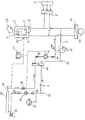
- the single drawing shows schematically the structure of an embodiment of the invention designed according to the system for hot water in a motorhome.
- the plant shown in the figure for hot water in a motor home comprises a hot water boiler 1 with an interior 2 for receiving the water to be heated and a surrounding, flowed through by heating water outside space 5, which is separated from the interior 2 and the environment by appropriate coats, said the inner jacket is used for heat transfer and consists of a material with good thermal conductivity.
- the interior 2 of the boiler has a cold water inlet 3 and a hot water outlet 4.
- the boiler is supplied with water, which may for example come from a suitable water tank.
- the exterior 5 of the hot water boiler 1 communicates with a secondary heating circuit 6, which is connected to a first heat exchanger 8, a second heat exchanger 10 and a third heat exchanger 17.
- the first heat exchanger 8 is supplied with the heat generated by a refrigerator 9 of the motorhome, which is normally in operation for 24 hours, so that the circulated in the Sekundärteil Vietnamese heating medium (water) is heated accordingly.
- the second heat exchanger 10 is acted upon via a fan 1 with the waste heat of the drive motor of the motor home, so that in this way the heat exchanger 10th flowing through heating medium undergoes an increase in temperature.
- About the mentioned third heat exchanger 17 of the secondary heating circuit is coupled to a primary heating circuit 7, which will be explained later.
- the secondary heating circuit 6 may be a conventional piping system having a drain port shown at 16. In the pipe system shut-off or metering valves 13 and 14 and temperature gauge 15 are arranged. A circulating pump 12 circulates the heating medium in the secondary circuit.
- a heating medium in the primary heating circuit 7 also serves water, which is provided with a suitable antifreeze.
- the content of the primary circuit 7 is about 2.5 l.
- the solar collector 22 is plate-shaped and can be arranged for example on the roof of the motor home. It comprises twelve spectacle tubes arranged parallel to one another, which are connected to the primary heating circuit 7 and through which the heating medium flows. Due to the solar energy trapped by the solar collector 22, the heating medium flowing through the collector tubes is heated and transfers the heat via the heat exchanger 17 to the heating medium flowing in the secondary heating circuit 6, via which the water to be heated in the hot water boiler 1 is finally heated.
- the solar collector 22 is a high-performance collector of the type mentioned in the general description part.
- a sensor 19 is mounted, which senses the temperature of the collector leaving the heating medium and emits a corresponding signal to a control / regulating device 21, from another Temperature sensor 20, which is attached to the boiler, is supplied with a further temperature signal.
- the device 21 controls or regulates a circulating pump 24 in the primary heating circuit 7 and the aforementioned circulating pump 12 in the secondary heating circuit 6.
- a flow meter 18 is provided in the primary heating circuit 7, which also supplies a measured value to the control / regulating device (not shown).
- the solar collector 22 is provided with an emptying device 23 and the primary heating circuit 7 with an emptying device 26 and corresponding shut-off / metering valves 27,28.
- the water flowing through the secondary heating circuit 6 is heated when the circulating pump 12 is switched on.
- the water flowing through the secondary heating circuit 6 is heated via the heat exchanger 17 when the solar collector 22 receives solar energy and the water in the primary heating circuit 7 is circulated through the heat exchanger 17.
- the three heat sources heat exchanger 8, heat exchanger 10 and heat exchanger 17
- the three heat sources can be switched on or off as required (not shown), to achieve a desired, optimized temperature. Normally, all the heat exchangers are coupled to the system, and upon reaching a desired boiler temperature, which is sensed via the sensor 20, the circulation pumps 12 and 18 are driven accordingly (turned off or switched back). When the temperature drops on the boiler, the pumps are switched on or their delivery rate is increased.
- the primary heating circuit 7 is provided with a suitable expansion vessel 25. Furthermore, a gas burner 29 is arranged with direct firing for the hot water boiler, which can be used for emergencies.
Landscapes
- Engineering & Computer Science (AREA)
- Mechanical Engineering (AREA)
- Physics & Mathematics (AREA)
- Thermal Sciences (AREA)
- Health & Medical Sciences (AREA)
- Epidemiology (AREA)
- General Health & Medical Sciences (AREA)
- Public Health (AREA)
- Heat-Pump Type And Storage Water Heaters (AREA)
- Sorption Type Refrigeration Machines (AREA)
- General Preparation And Processing Of Foods (AREA)
- Steam Or Hot-Water Central Heating Systems (AREA)
Claims (8)
- Installation pour la préparation d'eau chaude dans des véhicules routiers et des véhicules navals tels que des camping-cars, des caravanes, bateaux et similaires comprenant
un chauffe-eau (1) avec un volume intérieur (2) pour recueillir l'eau à chauffer,
caractérisée par un volume intérieur, un volume extérieur (5) dans lequel circule de l'eau chaude et qui entoure au moins en partie ce volume intérieur,
un circuit de chauffage secondaire (6) dans lequel circule de l'eau chaude et qui est raccordé au volume extérieur (5) du chauffe-eau (1)
un premier échangeur de chaleur (8) qui constitue une partie du circuit de chauffage secondaire (6) et qui est alimenté avec la chaleur dissipée par un réfrigérateur,
un deuxième échangeur de chaleur (10) qui constitue une partie du circuit de chauffage secondaire (6) et qui est alimenté avec la chaleur dissipée par le moteur d'entraînement du véhicule,
un circuit de chauffage primaire (7) qui présente un capteur solaire (22) et dans lequel circule de l'eau chaude, et
un troisième échangeur de chaleur (17) qui constitue une partie du circuit de chauffage primaire (7) et du circuit de chauffage secondaire (6) et qui est destiné à transmettre l'énergie calorifique du circuit de chauffage primaire (7) au circuit de chauffage secondaire (6). - Installation selon la revendication 1, caractérisée en ce qu'elle présente en outre un brûleur (29) pour chauffer l'eau se trouvant dans le chauffe-eau (1).
- Installation selon la revendication 1 ou 2, caractérisée en ce qu'elle a comme dispositif de chauffage du volume un radiateur qui constitue une partie du circuit de chauffage secondaire (6).
- Installation selon une des revendications 1 à 3,
caractérisée en ce qu'elle présente un quatrième échangeur de chaleur qui constitue une partie du circuit de chauffage secondaire (6) et qui est destiné au refroidissement à l'aide d'un circuit frigorifique. - Installation selon une des revendications précédentes, caractérisée en ce que le capteur solaire (22) est configuré comme un capteur en forme de plaque.
- Installation selon la revendication 5, caractérisée en ce que le capteur en forme de plaque présente une rangée de 10 - 14, en particulier de 12 tubes disposés parallèlement entre eux qui est raccordée au circuit primaire (7).
- Installation selon une des revendications précédentes, caractérisée en ce que les tubes du capteur solaire (22) sont configurés comme des tubes en forme de lunettes.
- Installation selon une des revendications précédentes, caractérisée en ce que le circuit de chauffage primaire (7) contient un produit antigel.
Priority Applications (3)
| Application Number | Priority Date | Filing Date | Title |
|---|---|---|---|
| DE50207016T DE50207016D1 (de) | 2002-09-19 | 2002-09-19 | Warmwasserbereitungsanlage |
| AT02020946T ATE328250T1 (de) | 2002-09-19 | 2002-09-19 | Warmwasserbereitungsanlage |
| EP02020946A EP1400764B1 (fr) | 2002-09-19 | 2002-09-19 | Installation de préparation d'eau chaude |
Applications Claiming Priority (1)
| Application Number | Priority Date | Filing Date | Title |
|---|---|---|---|
| EP02020946A EP1400764B1 (fr) | 2002-09-19 | 2002-09-19 | Installation de préparation d'eau chaude |
Publications (2)
| Publication Number | Publication Date |
|---|---|
| EP1400764A1 EP1400764A1 (fr) | 2004-03-24 |
| EP1400764B1 true EP1400764B1 (fr) | 2006-05-31 |
Family
ID=31896883
Family Applications (1)
| Application Number | Title | Priority Date | Filing Date |
|---|---|---|---|
| EP02020946A Expired - Lifetime EP1400764B1 (fr) | 2002-09-19 | 2002-09-19 | Installation de préparation d'eau chaude |
Country Status (3)
| Country | Link |
|---|---|
| EP (1) | EP1400764B1 (fr) |
| AT (1) | ATE328250T1 (fr) |
| DE (1) | DE50207016D1 (fr) |
Families Citing this family (14)
| Publication number | Priority date | Publication date | Assignee | Title |
|---|---|---|---|---|
| CN101634491B (zh) * | 2009-08-14 | 2011-04-13 | 李明强 | 太阳能、油气同步或交替及余热应用的热水系统和方法 |
| US9783024B2 (en) | 2015-03-09 | 2017-10-10 | Bergstrom Inc. | System and method for remotely managing climate control systems of a fleet of vehicles |
| US9874384B2 (en) | 2016-01-13 | 2018-01-23 | Bergstrom, Inc. | Refrigeration system with superheating, sub-cooling and refrigerant charge level control |
| US10589598B2 (en) | 2016-03-09 | 2020-03-17 | Bergstrom, Inc. | Integrated condenser and compressor system |
| US10081226B2 (en) | 2016-08-22 | 2018-09-25 | Bergstrom Inc. | Parallel compressors climate system |
| US12420616B2 (en) | 2016-08-22 | 2025-09-23 | Bergstrom, Inc. | Multi-compressor oil migration mitigation climate system |
| US10562372B2 (en) | 2016-09-02 | 2020-02-18 | Bergstrom, Inc. | Systems and methods for starting-up a vehicular air-conditioning system |
| US10675948B2 (en) | 2016-09-29 | 2020-06-09 | Bergstrom, Inc. | Systems and methods for controlling a vehicle HVAC system |
| US10724772B2 (en) | 2016-09-30 | 2020-07-28 | Bergstrom, Inc. | Refrigerant liquid-gas separator having an integrated check valve |
| US11448441B2 (en) | 2017-07-27 | 2022-09-20 | Bergstrom, Inc. | Refrigerant system for cooling electronics |
| US11420496B2 (en) | 2018-04-02 | 2022-08-23 | Bergstrom, Inc. | Integrated vehicular system for conditioning air and heating water |
| DE102018120376A1 (de) | 2018-08-21 | 2020-02-27 | Truma Gerätetechnik GmbH & Co. KG | Wassersystem für ein Freizeitfahrzeug |
| DE102018007951B4 (de) * | 2018-10-09 | 2024-06-13 | Truma Gerätetechnik GmbH & Co. KG | Anordnung zum Temperieren eines Innenraums |
| DE102020007489A1 (de) * | 2020-12-08 | 2022-06-09 | Truma Gerätetechnik GmbH & Co. KG | Temperierungsanordnung |
Family Cites Families (4)
| Publication number | Priority date | Publication date | Assignee | Title |
|---|---|---|---|---|
| US3973553A (en) * | 1975-07-07 | 1976-08-10 | Lanciault Joseph A | Combination solar heat collector and awning |
| US4680941A (en) * | 1986-05-21 | 1987-07-21 | Richardson Elvet M | Waste heating recovery system |
| DE9201907U1 (de) * | 1992-02-14 | 1992-04-09 | Albrecht, Franz, 7149 Freiberg | Vorrichtung zum Versorgen von Fahrzeugen, insbesondere Kraftfahrzeugen, mit Warmwasser |
| DE9317357U1 (de) * | 1993-11-12 | 1994-03-03 | Biese, Gabriela-Maria, 35606 Solms | Vorrichtung für Reisemobile, Wohnwagen, LKW, Bootskajüten etc. zur Beheizung eines Innenraumes und/oder der Warmwasserbereitung |
-
2002
- 2002-09-19 AT AT02020946T patent/ATE328250T1/de not_active IP Right Cessation
- 2002-09-19 EP EP02020946A patent/EP1400764B1/fr not_active Expired - Lifetime
- 2002-09-19 DE DE50207016T patent/DE50207016D1/de not_active Expired - Fee Related
Also Published As
| Publication number | Publication date |
|---|---|
| ATE328250T1 (de) | 2006-06-15 |
| EP1400764A1 (fr) | 2004-03-24 |
| DE50207016D1 (de) | 2006-07-06 |
Similar Documents
| Publication | Publication Date | Title |
|---|---|---|
| DE3242903C2 (fr) | ||
| DE102021209384B4 (de) | Wärmetauschersystem für ein Fahrzeug | |
| DE102019129555A1 (de) | Temperaturmanagementsystem für ein Fahrzeug | |
| DE112018003581B4 (de) | Kühlanordnung für ein Hybridfahrzeug mit einer elektrischen Antriebseinheit, einem Verbrennungsmotor und einem Abwärmerückgewinnungssystem | |
| DE1604205A1 (de) | Klimaanlage | |
| EP1400764A1 (fr) | Installation de préparation d'eau chaude | |
| DE102009042774A1 (de) | System für ein Kraftfahrzeug zum Erwärmen und/oder Kühlen einer Batterie und eines Kraftfahrzeuginnenraumes | |
| DE2411308C2 (de) | Heizungsanlage mit mindestens einer Wärmepumpe | |
| DE2606725A1 (de) | Sonnenenergiewandler | |
| DE102010048853A1 (de) | Klimatisierungssystem für ein Kraftfahrzeug sowie Verfahren zum Betrieb eines Klimatisierungssystems eines Kraftfahrzeuges | |
| EP1916486A2 (fr) | Système de collecte solaire | |
| EP2655106A1 (fr) | Véhicule à moteur muni d'une installation de climatisation | |
| DE102007063141A1 (de) | Heizungsvorrichtung zum Beheizen eines Gebäudes mittels einer von einer Verbrennungskraftmaschine angetriebenen Wärmepumpe | |
| DE202009006294U1 (de) | Vorrichtung zur Beheizung und/oder Stromversorgung eines Gebäudes | |
| WO2024002855A1 (fr) | Système de raccordement double pour pompes à chaleur et collecteurs géothermiques | |
| CH703472A1 (de) | Sonnenhybridkollektor. | |
| DE4312150C2 (de) | Verfahren zum Einstellen der Förderleistung einer Umwälzpumpe | |
| DE2711144A1 (de) | Verfahren zum betrieb einer waermepumpe | |
| EP0017975A1 (fr) | Système de chauffage avec pompe à chaleur fonctionnant par courant de nuit | |
| EP2063193A1 (fr) | Procédé destiné à la climatisation d'un bâtiment | |
| EP0811809A2 (fr) | Procédé d'opération d'une pompe à chaleur | |
| DE202010005387U1 (de) | Einrichtung zur Wiedergewinnung der Wärmeenergie aus der Abluft einer Gebäudelüftungsanlage | |
| WO2006024065A1 (fr) | Dispositif pour fournir de la chaleur a au moins un recepteur et evacuer de la chaleur de ce recepteur | |
| EP0019124B1 (fr) | Pompe de chaleur et procédé pour son fonctionnement | |
| DE20004881U1 (de) | Vorrichtung zur Temperierung von Gebäude-Innenräumen |
Legal Events
| Date | Code | Title | Description |
|---|---|---|---|
| PUAI | Public reference made under article 153(3) epc to a published international application that has entered the european phase |
Free format text: ORIGINAL CODE: 0009012 |
|
| AK | Designated contracting states |
Kind code of ref document: A1 Designated state(s): AT BE BG CH CY CZ DE DK EE ES FI FR GB GR IE IT LI LU MC NL PT SE SK TR |
|
| AX | Request for extension of the european patent |
Extension state: AL LT LV MK RO SI |
|
| 17P | Request for examination filed |
Effective date: 20040924 |
|
| AKX | Designation fees paid |
Designated state(s): AT BE BG CH CY CZ DE DK EE ES FI FR GB GR IE IT LI LU MC NL PT SE SK TR |
|
| GRAP | Despatch of communication of intention to grant a patent |
Free format text: ORIGINAL CODE: EPIDOSNIGR1 |
|
| GRAS | Grant fee paid |
Free format text: ORIGINAL CODE: EPIDOSNIGR3 |
|
| GRAA | (expected) grant |
Free format text: ORIGINAL CODE: 0009210 |
|
| AK | Designated contracting states |
Kind code of ref document: B1 Designated state(s): AT BE BG CH CY CZ DE DK EE ES FI FR GB GR IE IT LI LU MC NL PT SE SK TR |
|
| PG25 | Lapsed in a contracting state [announced via postgrant information from national office to epo] |
Ref country code: IE Free format text: LAPSE BECAUSE OF FAILURE TO SUBMIT A TRANSLATION OF THE DESCRIPTION OR TO PAY THE FEE WITHIN THE PRESCRIBED TIME-LIMIT Effective date: 20060531 Ref country code: IT Free format text: LAPSE BECAUSE OF FAILURE TO SUBMIT A TRANSLATION OF THE DESCRIPTION OR TO PAY THE FEE WITHIN THE PRESCRIBED TIME-LIMIT;WARNING: LAPSES OF ITALIAN PATENTS WITH EFFECTIVE DATE BEFORE 2007 MAY HAVE OCCURRED AT ANY TIME BEFORE 2007. THE CORRECT EFFECTIVE DATE MAY BE DIFFERENT FROM THE ONE RECORDED. Effective date: 20060531 Ref country code: NL Free format text: LAPSE BECAUSE OF FAILURE TO SUBMIT A TRANSLATION OF THE DESCRIPTION OR TO PAY THE FEE WITHIN THE PRESCRIBED TIME-LIMIT Effective date: 20060531 Ref country code: SK Free format text: LAPSE BECAUSE OF FAILURE TO SUBMIT A TRANSLATION OF THE DESCRIPTION OR TO PAY THE FEE WITHIN THE PRESCRIBED TIME-LIMIT Effective date: 20060531 Ref country code: CZ Free format text: LAPSE BECAUSE OF FAILURE TO SUBMIT A TRANSLATION OF THE DESCRIPTION OR TO PAY THE FEE WITHIN THE PRESCRIBED TIME-LIMIT Effective date: 20060531 Ref country code: GB Free format text: LAPSE BECAUSE OF FAILURE TO SUBMIT A TRANSLATION OF THE DESCRIPTION OR TO PAY THE FEE WITHIN THE PRESCRIBED TIME-LIMIT Effective date: 20060531 Ref country code: FI Free format text: LAPSE BECAUSE OF FAILURE TO SUBMIT A TRANSLATION OF THE DESCRIPTION OR TO PAY THE FEE WITHIN THE PRESCRIBED TIME-LIMIT Effective date: 20060531 |
|
| REG | Reference to a national code |
Ref country code: GB Ref legal event code: FG4D Free format text: NOT ENGLISH Ref country code: CH Ref legal event code: EP |
|
| REG | Reference to a national code |
Ref country code: IE Ref legal event code: FG4D Free format text: LANGUAGE OF EP DOCUMENT: GERMAN |
|
| REF | Corresponds to: |
Ref document number: 50207016 Country of ref document: DE Date of ref document: 20060706 Kind code of ref document: P |
|
| PG25 | Lapsed in a contracting state [announced via postgrant information from national office to epo] |
Ref country code: SE Free format text: LAPSE BECAUSE OF FAILURE TO SUBMIT A TRANSLATION OF THE DESCRIPTION OR TO PAY THE FEE WITHIN THE PRESCRIBED TIME-LIMIT Effective date: 20060831 Ref country code: DK Free format text: LAPSE BECAUSE OF FAILURE TO SUBMIT A TRANSLATION OF THE DESCRIPTION OR TO PAY THE FEE WITHIN THE PRESCRIBED TIME-LIMIT Effective date: 20060831 |
|
| PG25 | Lapsed in a contracting state [announced via postgrant information from national office to epo] |
Ref country code: ES Free format text: LAPSE BECAUSE OF FAILURE TO SUBMIT A TRANSLATION OF THE DESCRIPTION OR TO PAY THE FEE WITHIN THE PRESCRIBED TIME-LIMIT Effective date: 20060911 |
|
| PG25 | Lapsed in a contracting state [announced via postgrant information from national office to epo] |
Ref country code: LI Free format text: LAPSE BECAUSE OF NON-PAYMENT OF DUE FEES Effective date: 20060930 Ref country code: CH Free format text: LAPSE BECAUSE OF NON-PAYMENT OF DUE FEES Effective date: 20060930 Ref country code: MC Free format text: LAPSE BECAUSE OF NON-PAYMENT OF DUE FEES Effective date: 20060930 Ref country code: BE Free format text: LAPSE BECAUSE OF NON-PAYMENT OF DUE FEES Effective date: 20060930 |
|
| PG25 | Lapsed in a contracting state [announced via postgrant information from national office to epo] |
Ref country code: PT Free format text: LAPSE BECAUSE OF FAILURE TO SUBMIT A TRANSLATION OF THE DESCRIPTION OR TO PAY THE FEE WITHIN THE PRESCRIBED TIME-LIMIT Effective date: 20061031 |
|
| NLV1 | Nl: lapsed or annulled due to failure to fulfill the requirements of art. 29p and 29m of the patents act | ||
| GBV | Gb: ep patent (uk) treated as always having been void in accordance with gb section 77(7)/1977 [no translation filed] |
Effective date: 20060531 |
|
| REG | Reference to a national code |
Ref country code: IE Ref legal event code: FD4D |
|
| PGFP | Annual fee paid to national office [announced via postgrant information from national office to epo] |
Ref country code: AT Payment date: 20070327 Year of fee payment: 5 |
|
| PGFP | Annual fee paid to national office [announced via postgrant information from national office to epo] |
Ref country code: DE Payment date: 20070329 Year of fee payment: 5 |
|
| PLBE | No opposition filed within time limit |
Free format text: ORIGINAL CODE: 0009261 |
|
| STAA | Information on the status of an ep patent application or granted ep patent |
Free format text: STATUS: NO OPPOSITION FILED WITHIN TIME LIMIT |
|
| EN | Fr: translation not filed | ||
| 26N | No opposition filed |
Effective date: 20070301 |
|
| REG | Reference to a national code |
Ref country code: CH Ref legal event code: PL |
|
| BERE | Be: lapsed |
Owner name: STEINER, ROLAND Effective date: 20060930 Owner name: KROTER, FRANZ ADOLF Effective date: 20060930 |
|
| PG25 | Lapsed in a contracting state [announced via postgrant information from national office to epo] |
Ref country code: GR Free format text: LAPSE BECAUSE OF FAILURE TO SUBMIT A TRANSLATION OF THE DESCRIPTION OR TO PAY THE FEE WITHIN THE PRESCRIBED TIME-LIMIT Effective date: 20060901 Ref country code: FR Free format text: LAPSE BECAUSE OF FAILURE TO SUBMIT A TRANSLATION OF THE DESCRIPTION OR TO PAY THE FEE WITHIN THE PRESCRIBED TIME-LIMIT Effective date: 20070309 |
|
| PG25 | Lapsed in a contracting state [announced via postgrant information from national office to epo] |
Ref country code: AT Free format text: LAPSE BECAUSE OF NON-PAYMENT OF DUE FEES Effective date: 20070919 Ref country code: EE Free format text: LAPSE BECAUSE OF FAILURE TO SUBMIT A TRANSLATION OF THE DESCRIPTION OR TO PAY THE FEE WITHIN THE PRESCRIBED TIME-LIMIT Effective date: 20060531 Ref country code: BG Free format text: LAPSE BECAUSE OF FAILURE TO SUBMIT A TRANSLATION OF THE DESCRIPTION OR TO PAY THE FEE WITHIN THE PRESCRIBED TIME-LIMIT Effective date: 20060831 |
|
| PG25 | Lapsed in a contracting state [announced via postgrant information from national office to epo] |
Ref country code: TR Free format text: LAPSE BECAUSE OF FAILURE TO SUBMIT A TRANSLATION OF THE DESCRIPTION OR TO PAY THE FEE WITHIN THE PRESCRIBED TIME-LIMIT Effective date: 20060531 Ref country code: DE Free format text: LAPSE BECAUSE OF NON-PAYMENT OF DUE FEES Effective date: 20080401 Ref country code: LU Free format text: LAPSE BECAUSE OF NON-PAYMENT OF DUE FEES Effective date: 20060919 |
|
| PG25 | Lapsed in a contracting state [announced via postgrant information from national office to epo] |
Ref country code: FR Free format text: LAPSE BECAUSE OF FAILURE TO SUBMIT A TRANSLATION OF THE DESCRIPTION OR TO PAY THE FEE WITHIN THE PRESCRIBED TIME-LIMIT Effective date: 20060531 Ref country code: CY Free format text: LAPSE BECAUSE OF FAILURE TO SUBMIT A TRANSLATION OF THE DESCRIPTION OR TO PAY THE FEE WITHIN THE PRESCRIBED TIME-LIMIT Effective date: 20060531 |