EP1400796A2 - Kraft- und Drucksensor - Google Patents
Kraft- und Drucksensor Download PDFInfo
- Publication number
- EP1400796A2 EP1400796A2 EP03011318A EP03011318A EP1400796A2 EP 1400796 A2 EP1400796 A2 EP 1400796A2 EP 03011318 A EP03011318 A EP 03011318A EP 03011318 A EP03011318 A EP 03011318A EP 1400796 A2 EP1400796 A2 EP 1400796A2
- Authority
- EP
- European Patent Office
- Prior art keywords
- pressure
- volume
- force
- sensor
- membrane
- Prior art date
- Legal status (The legal status is an assumption and is not a legal conclusion. Google has not performed a legal analysis and makes no representation as to the accuracy of the status listed.)
- Withdrawn
Links
- 239000012528 membrane Substances 0.000 claims abstract description 51
- 238000003466 welding Methods 0.000 claims description 5
- 238000005259 measurement Methods 0.000 abstract description 11
- 230000001419 dependent effect Effects 0.000 abstract description 2
- 238000009530 blood pressure measurement Methods 0.000 abstract 1
- 230000008859 change Effects 0.000 description 18
- 239000007789 gas Substances 0.000 description 14
- 239000010408 film Substances 0.000 description 8
- 230000008901 benefit Effects 0.000 description 5
- 230000035945 sensitivity Effects 0.000 description 5
- 239000011888 foil Substances 0.000 description 4
- 239000012530 fluid Substances 0.000 description 3
- 239000002184 metal Substances 0.000 description 3
- 230000004044 response Effects 0.000 description 3
- 239000007787 solid Substances 0.000 description 3
- 230000009471 action Effects 0.000 description 2
- 238000010586 diagram Methods 0.000 description 2
- 238000005516 engineering process Methods 0.000 description 2
- 238000011156 evaluation Methods 0.000 description 2
- 238000004519 manufacturing process Methods 0.000 description 2
- 238000000034 method Methods 0.000 description 2
- 230000008569 process Effects 0.000 description 2
- 238000012360 testing method Methods 0.000 description 2
- XUIMIQQOPSSXEZ-UHFFFAOYSA-N Silicon Chemical compound [Si] XUIMIQQOPSSXEZ-UHFFFAOYSA-N 0.000 description 1
- 238000010276 construction Methods 0.000 description 1
- 238000013461 design Methods 0.000 description 1
- 238000011161 development Methods 0.000 description 1
- 230000018109 developmental process Effects 0.000 description 1
- 230000001939 inductive effect Effects 0.000 description 1
- 239000007788 liquid Substances 0.000 description 1
- 239000000463 material Substances 0.000 description 1
- 239000002985 plastic film Substances 0.000 description 1
- 229920006255 plastic film Polymers 0.000 description 1
- 229910052710 silicon Inorganic materials 0.000 description 1
- 239000010703 silicon Substances 0.000 description 1
- 239000010409 thin film Substances 0.000 description 1
Images


Classifications
-
- G—PHYSICS
- G01—MEASURING; TESTING
- G01L—MEASURING FORCE, STRESS, TORQUE, WORK, MECHANICAL POWER, MECHANICAL EFFICIENCY, OR FLUID PRESSURE
- G01L1/00—Measuring force or stress, in general
- G01L1/02—Measuring force or stress, in general by hydraulic or pneumatic means
Definitions
- the invention is based on a sensor of the type of the secondary Expectations. It is generally known to use transducer principles to measure forces to use a distance measurement or a voltage measurement. The evaluation takes place in voltage measurement, for example, piezoresistive and in the path principle optically, capacitive or inductive.
- the senor according to the invention with the features of the independent claims has the advantage that the measurement of a pressure in a closed volume can be used to measure a force or a fluid pressure (gas or liquid).
- the measurement of a pressure in a closed volume is easy to implement with simple means, which is why such a sensor can be produced particularly cost-effectively.
- the sensor according to the invention can measure both positive and negative forces. In this case, negative forces are forces in a given direction that are oriented the other way round as positive forces.
- the sensitivity of the sensor according to the invention can easily be set via the gas pressure in the closed volume and via the size of the volume or the membrane parameters (in particular. Diameter and thickness). It is also possible to carry out a self-test to check the plausibility of measurements, for example if the measurement volume has a leak. It is also advantageous that the measuring range for the forces to be measured can be adjusted via the design of the mechanically deformable parts, that is to say in particular through the membrane diameter of the force membrane and its thickness. Furthermore, it is also possible to use a sensor according to the invention for measuring pressures, in particular high pressures. Another advantage is that the force membrane can be made media-resistant.
- the measures listed in the subclaims are advantageous Further developments and improvements of the sensor specified in the main claim possible. It is particularly advantageous that the first volume and the second volume in the Have essentially the same temperature. This makes one work Temperature change leading to a change in pressure in the completed Volumes does not lead to a falsification of the measured values. It is also an advantage that the volumes by welding with or without a previous clamping, are hermetically sealed. This makes it possible to work in volumes enclosed fluids, that is, particularly gases, particularly safe and against the Protect against leaks. It is also advantageous that a mechanical stop is provided. This is a force overload protection or Pressure overload protection can be implemented. It is also advantageous that with the Pressure membrane is connected to a strain gauge. This makes it possible to the sensor according to the invention in a particularly simple manner and particularly inexpensively manufacture.
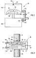
- FIG 1 is a schematic diagram to illustrate the measurement principle of the invention shown.
- the sensor according to the invention is identified by reference number 10 in the figures denotes and comprises a first volume 100 and a second volume 200.
- Die Volumes 100, 200 are hermetically sealed and include a fluid, in particular a gas, which is why they are also referred to below as gas volumes 100, 200.
- the first volume 100 is elastic due to external forces deformable solid.
- the external force that the first volume 100 enclosing body is deformed in Figure 1 with the reference number 20th shown arrow.
- the deformation of the in Figure 1 not with a Reference numeral designated, the first volume 100 enclosing body is by a dashed line is shown in the area of arrow 20.
- the deformation of the body leads to a pressure change in the first volume 100. Since the gas pressure in the first Volume 100 is temperature dependent according to the gas law, is used for compensation Reference volume used.
- the reference volume is the second volume 200 Determining the force 20 acting from the outside is the differential pressure between the two volumes 100, 200 measured by a gas pressure sensor according to the invention is provided as a relative pressure sensor and comprises a pressure membrane 50. For measurement of the relative pressure, the pressure membrane 50 is provided, on one side of which the pressure acts in the first volume 100 and on the second side the pressure of the second Volume 200 works.
- the first volume 100 is deformed by the external force 20, resulting in a Volume change and thus also a change in pressure in the closed Volume 100 or in the closed cavern or in the closed solid leads, which surrounds the first volume 100.
- that means for small deflections of the membrane 22 of the solid or Solid-state membrane 22, which is also referred to below as a force membrane 22 the proportionality between the action of force 20 and the change in volume or Given pressure change ..
- the pressure sensor has, in particular, the pressure membrane 50 due to the change in the relative pressure between the first volume 100 and the second volume 200 is deflected.
- the deflection of the membrane 50 is Sensible via sensor elements not shown in FIG.
- both the first volume 100 and the second volume 200 or reference volume 200 only hermetically after a welding process or after welding processes be closed.
- hermetic seal e.g. outward guided, open tubes serve, which in Figure 1, the reference numeral 110 for the first Wear volume 100 or reference numeral 210 for the second volume 200.
- the Tubes 110, 210 can be clamped and then welded be welded together.
- closing especially by welding, can the gas pressure in the volumes 100, 200 can be set. Is the gas pressure in both Equal volumes, a change in temperature does not lead to a pressure difference between the two volumes, i.e. there is no temperature response of the offset.
- the absolute pressure in both volumes rises or falls equally.
- a suitably set pressure between the outside environment and the volumes 100, 200 leads to implausible measured values in the event of a leak in one of the volumes 100, 200, for example for values outside the measuring range.
- Such implausible measurements can then be used to check the functionality of the sensor 10 according to the invention can be used, for example, during a self-test of one Plausibility check is carried out.
- FIG. 2 shows a first exemplary embodiment of a sensor arrangement according to the invention shown.
- 91 and 92 e.g. each denotes a grub screw, which above and is connected below to the sensor arrangement 10 according to the invention.
- the real one Sensor arrangement 10 includes force membrane 22, which is connected to first volume 100 borders.
- the first volume 100 is via a channel 110, which is also a tube 110 can be executed, connected to the outside world and connected with one Closure means 111 closed.
- the housing of the Sensor arrangement 10 according to the invention a recess for the second volume 200 , which in the illustrated embodiment also has a connecting passage 210 or has a tube 210 with a closure means 211, which, however, generally the sensor arrangement 10 according to the invention is not absolutely necessary.
- the housing of the sensor arrangement 10 is designed such that the first volume 100 and the second volume 200 access to two different sides of pressure membrane 50 have and act on them.
- the pressure membrane 50 is part of one in the Relative pressure sensor installed according to the invention, the Relative pressure sensor with its pressure membrane 50 built on a sensor base 52 is provided.
- the sensor base 52 is included in the exemplary embodiment in FIG a printed circuit board 60, from which electrical connecting lines 62 Connect sensor arrangement 10 electrically to the outside world.
- the first set screw 91 serves to apply the force 20 to the force membrane 22.
- FIG. 3 shows a second exemplary embodiment of the sensor 10 according to the invention shown.
- the strain gauges are with the Reference numeral 53 designates in FIG. 3 and is located on the pressure membrane 50.
- the strain gauges 53 serve as a measuring element for the deformation of the Pressure membrane 50.
- the second exemplary embodiment is shown in FIG. 3 a force to be measured or media pressure 20 is provided which acts on the deformable Force membrane 22 acts.
- the deformable force membrane 22 is with the first Volume 100 connected, which acts on one side of the pressure membrane 50. On the pressure force of the second volume 200 acts on the other side of the pressure membrane.
- the pressure membrane 50 is in one Sensor level 51 is provided, with sensor level 51 also being referred to as film 51.
- the film strain gauges consist of the carrier film 51 with one on it applied strain gauges.
- the carrier film can be a Metal foil or a plastic film, or a silicon membrane.
- the use of a metal foil as a carrier for the strain gauge structure has the Advantage that the housing of the sensor arrangement 10, which is also not shown in FIG is designated by a reference number, also made of the same metal can be and thus thermal expansion no mechanical stresses in cause or introduce the materials. This also results in this Principle of construction of the sensor 10 according to the invention generally a relatively good decoupling against lateral forces.
- the strain gauges on the pressure membrane 50 can for example by means of thin-film technology.
- the foil which serves to realize the pressure membrane 50, is in particular structured such that it carries the strain gauge on one side.
- the film can be structured from the rear in terms of sensitivity, as shown in FIG. 3 is designated by reference numeral 56.
- the structuring 56 and the Strain gauges can either be on the side of the first volume 100 or on the Side of the second volume 200 are attached.
- For decoupling differences in The thermal expansion on the sensor signal can additional back Structures which are provided with the reference symbol 55 in FIG. 3 are provided.
- FIG. 3 is a plan view of the second embodiment of the Sensor arrangement 10 according to the invention shown where the rear Structures 55, 56 of the film 51 can be seen in the top view.
- the Strain gauges 53 are not visible in the lower part of FIG. 3.
- FIG. 4 shows a further cross-sectional illustration of the second embodiment of the sensor arrangement 10 according to the invention shown.
- the first volume 100, the second volume 200, the film layer 51, the Pressure membrane 50 and the measuring element provided as strain gauge 53 is shown in FIG 4 shows the effective width 21 of the force 20 on the force membrane 22 shown as well as the effective thickness 23 of the force membrane 20 and the effective height 54 of the first volume 100.
- the force 20 only in a range of 80% of the effective width 53, that is for that given example acts in the range of a diameter of approx. 4 mm.
- the fat 23 of the force diaphragm 22 is, for example, 0.5 mm in size and the effective height of the first Volume 100, which is provided with the reference symbol 54, is according to the invention exemplary 0.05 mm in size.
- a rough estimate gives one Pressure change of 3.6 mbar between the first volume 100 and the second Volume 200 per 10 Newtons of acting force 20. This shows that for a membrane film pressure sensor optimizes the first volume 100 particularly well can be, that is, the first volume 100 can be built particularly small.
- FIG. 5 shows a third exemplary embodiment of the sensor arrangement according to the invention 10 shown.
- the first volume is 100
- the second volume is 200 acting force 20, the force membrane 22 and the pressure membrane 50 shown.
- the third exemplary embodiment of the sensor arrangement 10 according to the invention in Figure 5 is the use of a standard low pressure sensor as a relative pressure sensor intended.
- the first volume 100 has to be rebuilt so that the first Volume 100 can not be made as small as in the second embodiment in Figure 4.
- the effective width 21 or the diameter 21 is the Force 20 shown on the force membrane 22 and the effective height or Thickness of the force membrane 22.
- the relevant height 54 for the first volume 100 shown.
- the effective width 21 40 mm by way of example, the thickness 23 of the force membrane 22 is approximately 1 mm by way of example and at which the effective height 54 of the first volume 100 is approximately 3.5 mm is, there is a pressure change of only 0.56 mbar per 10 Newtons acting force 20.
- the main width of the first volume 100 with about 10 mm specified and the height of the structure of the relative sensor on the circuit board 60 with approx. 3 mm and its diameter with approx. 5 mm, which is not the case in FIG. 5 is explicitly shown.
- Figure 4 and Figure 5 represent variants with small and large gas volumes.
- all parameters such as are to adapt the output signal (pressure change) e.g. Shape and size of the gas volumes as well as shape, diameter, thickness and Clamping of the force membrane can be varied.
Landscapes
- Physics & Mathematics (AREA)
- General Physics & Mathematics (AREA)
- Measuring Fluid Pressure (AREA)
Abstract
Description
Ein weiterer Vorteil ist es, dass die Kraftmembran medienbeständig gestalten werden kann.
Claims (6)
- Sensor (10) zur Messung einer Kraft (20), dadurch gekennzeichnet, dass ein erstes abgeschlossenes Volumen (100) und ein zweites abgeschlossenes Volumen (200) vorgesehen ist, wobei eine Druckmembran (50) vorgesehen ist, auf deren einen Seite der Druck des ersten Volumens (100) wirkt und auf deren zweiten Seite der Druck des zweiten Volumens (200) wirkt, wobei die Kraft (20) auf eine Kraftmembran (22) wirkt und wobei der Druck im ersten Volumen 100 abhängig von der Kraft (20) auf die Kraftmembran (22) ist.
- Sensor (10) nach Anspruch 1, dadurch gekennzeichnet, dass das erste Volumen (100) und das zweite Volumen (200) im Wesentlichen die gleiche Temperatur aufweisen.
- Sensor (10) nach Anspruch 1 oder 2, dadurch gekennzeichnet, dass die Volumina (100, 200) durch Verschweißung mit oder ohne vorheriges Klemmen, hermetisch abgeschlossen sind.
- Sensor (10) nach einem der vorhergehenden Ansprüche, dadurch gekennzeichnet, dass ein mechanischer Anschlag (120) vorgesehen ist.
- Sensor (10) nach einem der vorhergehenden Ansprüche, dadurch gekennzeichnet, dass mit der Druckmembran (50) ein Dehnmessstreifen (53) verbunden ist.
- Sensor zur Messung eines Druckes, wobei es zur Messung des Druckes vorgesehen ist, eine durch den Druck hervorgerufene Druckkraft auf eine Messfläche mittels eines Sensors (10) zur Messung einer Kraft nach einem der vorhergehenden Ansprüche zu messen.
Applications Claiming Priority (2)
| Application Number | Priority Date | Filing Date | Title |
|---|---|---|---|
| DE10243515 | 2002-09-19 | ||
| DE10243515A DE10243515A1 (de) | 2002-09-19 | 2002-09-19 | Sensor |
Publications (2)
| Publication Number | Publication Date |
|---|---|
| EP1400796A2 true EP1400796A2 (de) | 2004-03-24 |
| EP1400796A3 EP1400796A3 (de) | 2005-06-29 |
Family
ID=31896193
Family Applications (1)
| Application Number | Title | Priority Date | Filing Date |
|---|---|---|---|
| EP03011318A Withdrawn EP1400796A3 (de) | 2002-09-19 | 2003-05-19 | Kraft- und Drucksensor |
Country Status (4)
| Country | Link |
|---|---|
| US (1) | US7073400B2 (de) |
| EP (1) | EP1400796A3 (de) |
| JP (1) | JP2004109134A (de) |
| DE (1) | DE10243515A1 (de) |
Families Citing this family (3)
| Publication number | Priority date | Publication date | Assignee | Title |
|---|---|---|---|---|
| JP2009050589A (ja) * | 2007-08-28 | 2009-03-12 | Terumo Corp | Pfo閉鎖デバイス |
| US10496209B2 (en) * | 2017-03-31 | 2019-12-03 | Apple Inc. | Pressure-based force and touch sensing |
| US11847311B2 (en) * | 2019-05-22 | 2023-12-19 | Apple Inc. | Characterization of a venting state or other system parameter that affects the characterization of a force applied to a device |
Family Cites Families (12)
| Publication number | Priority date | Publication date | Assignee | Title |
|---|---|---|---|---|
| FR2638524B1 (fr) * | 1988-10-27 | 1994-10-28 | Schlumberger Prospection | Capteur de pression utilisable dans les puits de petrole |
| DE8905918U1 (de) * | 1989-05-11 | 1989-07-13 | Siemens AG, 1000 Berlin und 8000 München | Differenzdruck-Meßzelle mit zwei mit Druckzuleitungen versehenen Meßkammern |
| JP2890662B2 (ja) * | 1990-04-25 | 1999-05-17 | ソニー株式会社 | 樹脂封止型半導体装置の製造方法とそれに用いるリードフレーム |
| US5095755A (en) * | 1990-11-01 | 1992-03-17 | Rosemount Inc. | Isolator for pressure transmitter |
| JPH04258176A (ja) * | 1991-02-12 | 1992-09-14 | Mitsubishi Electric Corp | 半導体圧力センサ |
| US5262641A (en) * | 1991-12-30 | 1993-11-16 | Honeywell Inc. | Compensation mechanism for a pressure sensor having counterweight mechanism |
| US6148673A (en) * | 1994-10-07 | 2000-11-21 | Motorola, Inc. | Differential pressure sensor and method thereof |
| EP0764839A1 (de) * | 1995-09-22 | 1997-03-26 | Endress + Hauser GmbH + Co. | Druck- oder Differenzdruckmessgerät |
| US6105436A (en) * | 1999-07-23 | 2000-08-22 | Mks Instruments, Inc. | Capacitive pressure transducer with improved electrode support |
| DE10031135A1 (de) * | 2000-06-30 | 2002-01-17 | Grieshaber Vega Kg | Druckmeßvorrichtung |
| DE10034390C2 (de) * | 2000-07-14 | 2003-06-26 | Eads Deutschland Gmbh | Drucksensor und Verfahren zu seiner Herstellung, sowie Verbrennungskraftmaschine mit Drucksensor |
| US20020073783A1 (en) * | 2000-10-18 | 2002-06-20 | Endevco Corporation | Pressure sensor |
-
2002
- 2002-09-19 DE DE10243515A patent/DE10243515A1/de not_active Withdrawn
-
2003
- 2003-05-19 EP EP03011318A patent/EP1400796A3/de not_active Withdrawn
- 2003-09-09 US US10/658,059 patent/US7073400B2/en not_active Expired - Fee Related
- 2003-09-17 JP JP2003325062A patent/JP2004109134A/ja active Pending
Non-Patent Citations (1)
| Title |
|---|
| None * |
Also Published As
| Publication number | Publication date |
|---|---|
| DE10243515A1 (de) | 2004-04-01 |
| JP2004109134A (ja) | 2004-04-08 |
| US7073400B2 (en) | 2006-07-11 |
| US20040093962A1 (en) | 2004-05-20 |
| EP1400796A3 (de) | 2005-06-29 |
Similar Documents
| Publication | Publication Date | Title |
|---|---|---|
| EP1269135B1 (de) | Drucksensormodul | |
| DE4335588C2 (de) | Drucksensor | |
| DE102004048367B4 (de) | Verfahren zur Befüllung eines Druckmessaufnehmers | |
| DE2829083A1 (de) | Vom medium unabhaengiger differentieller druckumwandler | |
| EP3370051A2 (de) | Drucksensor sowie druckmessverfahren | |
| DE102007042439A1 (de) | Drucksensor mit druckempfindlicher Membran | |
| EP2335039B1 (de) | Sensoranordnung, verfahren zum betrieb einer sensoranordnung und verfahren zur herstellung einer sensoranordnung | |
| DE102016008508A1 (de) | Differenzdruckwandleranordnung mit Überdruckschutz | |
| DE102009048702A1 (de) | Drucksensor mit nichtlinearer Kennlinienkurve | |
| DE10130375B4 (de) | Differenzdrucksensor | |
| WO2016102121A1 (de) | Differenzdrucksensor und differenzdruckmessaufnehmer mit einem solchen differenzdrucksensor | |
| DE102018105867A1 (de) | Differenzdrucksensor zum Bestimmen einer Differenzdruckgröße | |
| DE10357353B4 (de) | Vorrichtung zum Testen von wenigstens einem Drucksensor | |
| DE19608310C1 (de) | Differenzdruckmeßumformereinheit mit einem Überlastschutzsystem | |
| DE102012025070A1 (de) | Hydraulisches Messwerk mit koplanaren Druckeingängen und Differenzdrucksensor mit einem solchen Messwerk | |
| EP3707485A1 (de) | Drucksensorsystem mit schutz vor einfrierendem medium | |
| DE10313738A1 (de) | Kapazitiver mikromechanischer Drucksensor | |
| EP1400796A2 (de) | Kraft- und Drucksensor | |
| EP3207348B1 (de) | Verfahren zur ermittlung eins druckmesssignals und druckmessanordnung hierfür | |
| DE102007057694B4 (de) | Leckageerkennung bei einem Gehäuse eines elektronischen Steuergeräts | |
| EP3161441B1 (de) | Drucksensor zur erfassung eines drucks eines fluiden mediums in einem messraum | |
| DE102010043824B4 (de) | Druckmessumformer | |
| DE102009045158A1 (de) | Sensoranordnung und Verfahren zur Herstellung einer Sensoranordnung | |
| WO2022037859A1 (de) | Differenzdruckmessaufnehmer zur bestimmung des differenzdrucks von zwei drücken | |
| WO2022037860A1 (de) | Differenzdruckmessaufnehmer |
Legal Events
| Date | Code | Title | Description |
|---|---|---|---|
| PUAI | Public reference made under article 153(3) epc to a published international application that has entered the european phase |
Free format text: ORIGINAL CODE: 0009012 |
|
| AK | Designated contracting states |
Kind code of ref document: A2 Designated state(s): AT BE BG CH CY CZ DE DK EE ES FI FR GB GR HU IE IT LI LU MC NL PT RO SE SI SK TR |
|
| AX | Request for extension of the european patent |
Extension state: AL LT LV MK |
|
| PUAL | Search report despatched |
Free format text: ORIGINAL CODE: 0009013 |
|
| AK | Designated contracting states |
Kind code of ref document: A3 Designated state(s): AT BE BG CH CY CZ DE DK EE ES FI FR GB GR HU IE IT LI LU MC NL PT RO SE SI SK TR |
|
| AX | Request for extension of the european patent |
Extension state: AL LT LV MK |
|
| 17P | Request for examination filed |
Effective date: 20051229 |
|
| AKX | Designation fees paid |
Designated state(s): DE FR GB |
|
| 17Q | First examination report despatched |
Effective date: 20060627 |
|
| 17Q | First examination report despatched |
Effective date: 20060627 |
|
| STAA | Information on the status of an ep patent application or granted ep patent |
Free format text: STATUS: THE APPLICATION IS DEEMED TO BE WITHDRAWN |
|
| 18D | Application deemed to be withdrawn |
Effective date: 20070605 |