EP1400875B1 - Dispositif de fixation d'un bracelet sur une boîte de montre - Google Patents
Dispositif de fixation d'un bracelet sur une boîte de montre Download PDFInfo
- Publication number
- EP1400875B1 EP1400875B1 EP02020804A EP02020804A EP1400875B1 EP 1400875 B1 EP1400875 B1 EP 1400875B1 EP 02020804 A EP02020804 A EP 02020804A EP 02020804 A EP02020804 A EP 02020804A EP 1400875 B1 EP1400875 B1 EP 1400875B1
- Authority
- EP
- European Patent Office
- Prior art keywords
- lugs
- pivots
- hinge pin
- external
- recess
- Prior art date
- Legal status (The legal status is an assumption and is not a legal conclusion. Google has not performed a legal analysis and makes no representation as to the accuracy of the status listed.)
- Expired - Lifetime
Links
- 239000002184 metal Substances 0.000 description 3
- 239000010985 leather Substances 0.000 description 2
- 230000000717 retained effect Effects 0.000 description 2
- 239000003086 colorant Substances 0.000 description 1
- 230000008094 contradictory effect Effects 0.000 description 1
- 238000004519 manufacturing process Methods 0.000 description 1
- 239000000463 material Substances 0.000 description 1
- 235000019640 taste Nutrition 0.000 description 1
- 210000000707 wrist Anatomy 0.000 description 1
Images

Classifications
-
- G—PHYSICS
- G04—HOROLOGY
- G04B—MECHANICALLY-DRIVEN CLOCKS OR WATCHES; MECHANICAL PARTS OF CLOCKS OR WATCHES IN GENERAL; TIME PIECES USING THE POSITION OF THE SUN, MOON OR STARS
- G04B37/00—Cases
- G04B37/14—Suspending devices, supports or stands for time-pieces insofar as they form part of the case
- G04B37/1486—Arrangements for fixing to a bracelet
-
- A—HUMAN NECESSITIES
- A44—HABERDASHERY; JEWELLERY
- A44C—PERSONAL ADORNMENTS, e.g. JEWELLERY; COINS
- A44C5/00—Bracelets; Wrist-watch straps; Fastenings for bracelets or wrist-watch straps
- A44C5/14—Bracelets; Wrist-watch straps; Fastenings for bracelets or wrist-watch straps characterised by the way of fastening to a wrist-watch or the like
- A44C5/147—Watchcase itself used as fastener
-
- Y—GENERAL TAGGING OF NEW TECHNOLOGICAL DEVELOPMENTS; GENERAL TAGGING OF CROSS-SECTIONAL TECHNOLOGIES SPANNING OVER SEVERAL SECTIONS OF THE IPC; TECHNICAL SUBJECTS COVERED BY FORMER USPC CROSS-REFERENCE ART COLLECTIONS [XRACs] AND DIGESTS
- Y10—TECHNICAL SUBJECTS COVERED BY FORMER USPC
- Y10T—TECHNICAL SUBJECTS COVERED BY FORMER US CLASSIFICATION
- Y10T24/00—Buckles, buttons, clasps, etc.
- Y10T24/21—Strap tighteners
- Y10T24/2143—Strap-attached folding lever
- Y10T24/2155—Jewelry-watch straps
-
- Y—GENERAL TAGGING OF NEW TECHNOLOGICAL DEVELOPMENTS; GENERAL TAGGING OF CROSS-SECTIONAL TECHNOLOGIES SPANNING OVER SEVERAL SECTIONS OF THE IPC; TECHNICAL SUBJECTS COVERED BY FORMER USPC CROSS-REFERENCE ART COLLECTIONS [XRACs] AND DIGESTS
- Y10—TECHNICAL SUBJECTS COVERED BY FORMER USPC
- Y10T—TECHNICAL SUBJECTS COVERED BY FORMER US CLASSIFICATION
- Y10T24/00—Buckles, buttons, clasps, etc.
- Y10T24/47—Strap-end-attaching devices
- Y10T24/4718—Watch pintle connected
Definitions
- the present invention relates to a device for attaching a watch strap to a watch case having a hinge secured to the watch case in which two pivots are sliding subjected to the action of a first return spring tending to remove them from in such a way that the external ends of the pivots emerge out of the lateral faces of said hinge and comprising a fastening element fixed to or integrated into the end of a bracelet provided with two lugs defining between them a space intended to receive the hinge, each these tabs having an axial recess opening into the space between these tabs.
- the object of the present invention is to provide an easy solution to this contradictory problem by providing a device for attaching a bracelet to a watch case that allows interchangeability of the bracelet can be performed easily and quickly by the user. In particular, this operation does not require the use of a tool. Simultaneously, this solution guarantees an improvement in the safety of this operation due to the fact that the risk that the connection between the interchangeable strap and the watch is worn out is greatly reduced.
- this invention allows users to fix themselves on a watch bracelets according to their tastes, for example in different colors or different materials such as metal, leather etc.
- the present invention as defined by the claims, relates to a device for attaching a watch strap to a watch case which is distinguished by the fact that the axial recess is extended towards the external lateral faces of the legs by a port housing a counter-pivot slidably mounted in this recess and carrying a pusher attached to the outer ends of the counter-pivots, and in that the hinge has on its side faces an annular housing having a groove defining a preferred orientation, this annular housing being adapted to cooperate with a protrusion placed on the inner faces of the tabs.
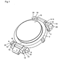
- the figure 1 illustrates a watch case equipped with the fastening device according to the invention, coupled to connection pieces that comprise the ends of the bracelet.
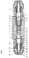
- the figure 2 is a partial section through the AA line of the figure 1 following a plane perpendicular to the bottom of the watch case.
- the figure 3 is an illustration of the operation of setting up the bracelet on the watch case.
- the device for attaching a bracelet to a watch case illustrated at figure 1 comprises a hinge 1 integral with the watch case 2, replacing in a way the usual horns, and a fastening element 3 intended to be fixed on the end of a bracelet to be coupled to the watch case 2.
- This element 3 can also be integrated manufacturing at the end of the bracelet, as shown in figure 3 .
- Each hinge 1 has a transverse through passage having three parts, a small diameter portion 4 opening on one of its side edges, a median portion 5 of larger diameter and a portion of large diameter 6, provided with a thread 7, opening on the other side edge of the hinge 1.
- transverse passage 4 5, 6 are housed two pivots 8, 9 having a central portion of a diameter corresponding to the diameter of the middle portion 5 of the through passage of the hinge 1.
- Each pivot has an inner end of smaller diameter introduced in a first coil spring 10 also housed in the transverse passage 4, 5, 6 and tending to separate the pivots 8, 9 from one another.
- a threaded bush 11 is screwed into the thread 7 and has a terminal bore 12 of the same diameter as the small diameter portion 4 of the transverse passage 4, 5, 6 of the hinge 1 opening into a housing 13 having a diameter corresponding to that of the medial portion of the transverse passage 4, 5, 6. In this housing 13 slides the middle part of the pivot 9.
- the hinge 1 further comprises, on its lateral faces, an annular housing 25 surrounding, leaving empty an annular space, the outer end portions of the pivot 8, 9 emerging in these side faces.
- this annular housing 25 has a groove 26, as illustrated in FIG. figure 3 , which defines a preferred orientation of the interchangeable strap intended to be placed on the hinge 1.
- This groove 26 is preferably oriented perpendicularly downwards relative to the watch case. The angle between a line along one side of this groove 26 and the plane of the bottom of the watch case is thus included, preferably between 80 ° and 100 °, and is, in the example shown, a right angle.
- the annular housing 25 is deeper in the face of the hinge 1 intended to receive the sleeve 11, so that the effective depth of the annular housing 25 is identical to each side face of the hinge 1 once the sleeve 11 is screwed into the hinge 1.
- the fastening element 3 can be constituted by the last link of a metal bracelet or by a piece integrated into the end of a leather strap.
- the element 3 is part of the end of the bracelet.
- this element 3 comprises a stud provided with a bore.
- This post is intended to be attached to the end of a metal bracelet with a pin passing through this piercing.
- This element 3 further comprises two tabs 15 separated by a recess 16 for receiving the hinge 1 of the watch case.
- These lugs 15 each comprise a recess opening with a portion 17b of larger diameter having a thread 17c on their outer lateral faces. A portion 17a of smaller diameter of this recess opens on the inner edge of these tabs 15.
- End pieces 19 are screwed into the parts 17b of the recesses of the lugs 15 using the thread 17c.
- These tips 19 comprise a through hole 22 extending the recesses outwardly and in which slides a counter-pivot 21.
- These tips 19 may consist of an inner portion 19a mainly of cylindrical shape and an outer portion 19b which, in this case, may be applied against the outer face of the lugs 15 by an outer shoulder of the outer faces of the inner portions 19a. as shown in figure 2 .
- the end pieces 19 could still be made in one piece.
- the inner part 19a of the end pieces 19 further comprises, towards its inner face, a shoulder 19c separating the housing formed by the recess 17a, 17b of the tabs 15 and the through orifice 22 in two parts and simultaneously defining a smaller diameter than that the through hole 22, which is preferably identical to that of the recess 17a, 17b.
- the counter pivots 21 comprise two parts of different diameters.
- An inner portion of the counter-pivot 21b has a larger diameter corresponding to that of the recess 17a, 17b in which the portion 21b slides so that it is retained by the shoulder 19c, against which it abuts .
- An outer portion of the counter-pivot 21a has a smaller diameter corresponding to that defined by the shoulder 19c of the ends 19.
- a second return spring 18 can therefore be housed between the outer portion of the counter-pivot 21a and the inner wall. of the through orifice 22 of the end pieces 19.
- the second return spring 18 is applied from its inner face against the outer face of the shoulder 19c, which it tends to push outwardly a push rod 20 fixed at the outer end of the outer portion of the pivot 21 and is housed in the outer portion 19a of the end pieces 19.
- This pusher 20 may for example be screwed to the thread 24 of the outer end 23 of the counter-pivot 21.
- the normal position of the pushers 20, held by the second springs 18, is that in which the inner portion 21b of the counter-pivots 21 abuts against the shoulder 19c of the tips 19, the pushers being pushed out by these springs 18.
- each lug 15 In the inner face of each lug 15 is arranged a protuberance 27 of annular shape whose depth corresponds to the diameter of the end of the pivots 8, 9 emerging laterally from the hinge 1 and to the aforementioned effective depth of the annular housing 25.
- the width of this protrusion 27 corresponds to the width of the groove 26 arranged in the annular housing 25 so that the bracelet can be introduced, in the preferred orientation mentioned above, in its position in which the connection with the watch case is installed. .
- the ends of the pivots 8,9 emerging laterally from the hinge 1 are, in order to stabilize this connection, housed in a central recess 29 of the protuberances 27 representing a coaxial extension of the same diameter of the recess 17a, 17b of the lugs 15
- the protuberances 27 further comprise a guide groove 28 arranged on the protuberances so that, by bringing the bracelet in the preferred orientation to the hinge 1 , the outer ends between pivots 8, 9 engage in the recesses 29 of the protuberances 27 of the hinge 1.
- These guide grooves 28 are formed in particular in the protuberances 27 preferably at their outer side seen in the axis of the bracelet , as indicated in figure 3 .
- the outer walls of the protuberances 27 may comprise an aligned straight portion, the bracelet being oriented in the preferred direction at the bottom of the watch case, with the walls of the groove 26 to reinforce the need for 'orient the pieces correctly to fit or remove the bracelet.
- the user To detach a bracelet from the watch case 2, the user must simultaneously push the two pushers 20 and orient the bracelet perpendicularly downwards relative to the watch case. By pressing the pushers, it depresses the counter-pivots 21 which retracts the pivots 8, 9 in the hinge 1 (see figure 2 ). By pulling on the bracelet in the axis of the latter which is in the preferred orientation for this operation, the connecting element 3 is then separated from the hinge 1 because the protuberance 27 can leave the annular housing 25 and the The bracelet is detached from the watch case 2. Because it is necessary to simultaneously press the two pushers 20 and orient the bracelet perpendicularly downwards, which is possible only if the watch is not on the wrist, this gives double security. At the same time, this operation does not require a tool and therefore allows the owner of the watch to change the bracelet of his watch at any time.
- the user presents the connecting element 3 below the hinge 1.
- the protuberances 27 can be introduced into the annular housing 25, the guide grooves 28 being engaged on the pivots 8, 9 out of the hinge 1.
- the user then forces the fastening element 3 on the hinge, the inclined planes of the guide grooves 28 retract the pivots 8, 9 until the recess or recesses central 29 are opposite these pivots 8, 9 and that they enter these recesses 29 under the action of the spring 10.
- the bracelet is thus secured to the watch case.
- this fixing device it is easily and quickly, especially without tools, change its watch strap, this while being sure of a good connection between the bracelet and the watch case.
Landscapes
- Physics & Mathematics (AREA)
- General Physics & Mathematics (AREA)
- Electric Clocks (AREA)
- Adornments (AREA)
- Buckles (AREA)
- Hinges (AREA)
- Auxiliary Devices For And Details Of Packaging Control (AREA)
- Telephone Function (AREA)
Description
- La présente invention concerne un dispositif de fixation d'un bracelet de montre sur une boîte de montre comportant un gond solidaire de la boîte de montre dans lequel coulissent deux pivots soumis à l'action d'un premier ressort de rappel tendant à les écarter de manière à ce que les extrémités externes des pivots émergent hors des faces latérales dudit gond et comportant un élément de fixation fixé à ou intégré dans l'extrémité d'un bracelet muni de deux pattes définissant entre elles un espace destiné à recevoir le gond, chacune de ces pattes comportant un évidement axial débouchant dans l'espace compris entre ces pattes.
- Un exemple d'un tel dispositif de fixation est donné dans le document
EP 0046622 . - Cette invention doit être vue dans le contexte de bracelets interchangeables permettant de changer le bracelet d'une montre pour certaines occasions ou selon la volonté du propriétaire de la montre. De tels bracelets interchangeables existent, néanmoins comportant un certain nombres de désavantages. Soit les bracelets de ce genre se démontent et montent facilement et sans outils par l'utilisateur, mais ont dans ce cas l'inconvénient de risquer de se défaire tout seul et ainsi de faire tomber ou même perdre la montre. Soit ce risque est affaibli ou écarté, les bracelets ayant dans ce cas souvent le désavantage de nécessiter un outil afin d'être changés, ceci étant contraire au but envisagé.
- Le but de la présente invention est d'apporter une solution facile à ce problème contradictoire en réalisant un dispositif de fixation d'un bracelet sur une boîte de montre qui permette une interchangeabilité du bracelet pouvant être effectuée facilement et rapidement par l'utilisateur. En particulier, cette opération ne nécessite pas le recours à un outil. Simultanément, cette solution garanti une amélioration au niveau de la sécurité de cette opération due au fait que le risque que la liaison entre le bracelet interchangeable et la montre ne se défasse est grandement diminué. Ainsi, cette invention permet aux utilisateurs de fixer eux-mêmes sur une montre des bracelets selon leurs goûts, par exemple en différentes couleurs ou différentes matières comme en métal, cuir etc.
- La présente invention comme défini par les revendications, a pour objet un dispositif de fixation d'un bracelet de montre sur une boîte de montre qui se distingue par le fait que l'évidement axial est prolongé en direction des faces latérales externes des pattes par un orifice hébergeant un contre-pivot monté de façon coulissante dans cet évidement et portant un poussoir fixé aux extrémités externes des contre-pivots, et par le fait que le gond comporte sur ses faces latérales un logement annulaire ayant une rainure définissant une orientation privilégiée, ce logement annulaire étant destiné à coopérer avec une protubérance placée sur les faces intérieures des pattes.
- Les dessins annexés illustrent schématiquement et à titre d'exemple une forme d'exécution du dispositif de fixation d'un bracelet sur une boîte de montre selon l'invention.
- La
figure 1 illustre une boîte de montre équipée du dispositif de fixation selon l'invention, accouplée à des pièces de liaisons que comportent les extrémités du bracelet. - La
figure 2 est une coupe partielle passant par la ligne A-A de lafigure 1 suivant un plan perpendiculaire au fond de la boîte de montre. - La
figure 3 est une illustration de l'opération de mise en place du bracelet sur la boîte de montre. - Le dispositif de fixation d'un bracelet sur une boîte de montre illustré à la
figure 1 comporte un gond 1 solidaire de la boîte de montre 2, remplaçant en quelque sorte les cornes habituelles, et un élément de fixation 3 destiné à être fixé sur l'extrémité d'un bracelet devant être accouplé à la boîte de montre 2. Cet élément 3 peut également être intégré de fabrication à l'extrémité du bracelet, comme le montre lafigure 3 . - Chaque gond 1 comporte un passage transversal traversant présentant trois parties, une partie de faible diamètre 4 débouchant sur l'une de ses tranches latérales, une partie médiane 5 de plus grand diamètre et une partie de grand diamètre 6, munie d'un filetage 7, débouchant sur l'autre tranche latérale du gond 1.
- Dans ce passage transversal 4, 5, 6 sont logés deux pivots 8, 9 comportant une partie centrale d'un diamètre correspondant au diamètre de la partie médiane 5 du passage traversant du gond 1. Chaque pivot comporte une extrémité interne de plus faible diamètre introduite dans un premier ressort à boudin 10 également logé dans le passage transversal 4, 5, 6 et tendant à écarter les pivots 8, 9 l'un de l'autre.
- Une douille filetée 11 est vissée dans le filetage 7 et comporte un perçage terminal 12 de même diamètre que la partie 4 de faible diamètre du passage transversal 4, 5, 6 du gond 1 débouchant dans un logement 13 présentant un diamètre correspondant à celui de la partie médiane du passage transversal 4, 5, 6. Dans ce logement 13 coulisse la partie médiane du pivot 9.
- Ainsi, en position de service les pivots 8, 9 coulissent transversalement dans le gond 1 et sont soumis à l'action du ressort 10 qui tend à les écarter l'un de l'autre. Les parties terminales externes du pivot 8, 9 émergent des faces latérales du gond 1 et les pivots 8, 9 sont retenus par leur épaulement 14 venant en butée contre le gond 1 respectivement la douille 11 vissée dans le gond 1 comme illustré à la
figure 2 . - Le gond 1 comporte encore, sur ses faces latérales, un logement annulaire 25 entourant, en laissant vide un espace annulaire, les parties terminales externes du pivot 8, 9 émergeant dans ces faces latérales. De plus, ce logement annulaire 25 comporte une rainure 26, comme illustré à la
figure 3 , qui défini une orientation privilégiée du bracelet interchangeable destinée à être mise en place sur le gond 1. Cette rainure 26 est de préférence orientée perpendiculairement vers le bas par rapport à la boîte de montre. L'angle entre une ligne longeant un côté de cette rainure 26 et le plan du fond de la boîte de montre est ainsi compris, de préférence entre 80° et 100°, et est, dans l'exemple illustré, un angle droit. Le logement annulaire 25 est plus profond à la face du gond 1 destiné à recevoir la douille 11, de manière à ce que la profondeur effective des logements annulaires 25 est identique à chaque face latérale du gond 1 une fois que cette douille 11 est vissée dans le gond 1. - L'élément de fixation 3 peut être constitué par le dernier maillon d'un bracelet métallique ou par une pièce intégrée dans l'extrémité d'un bracelet cuir. Dans l'exemple illustré à la
figure 3 , l'élément 3 fait partie de l'extrémité du bracelet. Dans l'exemple illustré à lafigure 1 , cet élément 3 comporte un tenon muni d'un perçage. Ce tenon est destiné à être fixé à l'extrémité d'un bracelet métallique à l'aide d'une goupille passant dans ce perçage. Cet élément 3 comporte encore deux pattes 15 séparées par un évidement 16 destiné à recevoir le gond 1 de la boîte de montre. Ces pattes 15 comportent chacune un évidement débouchant avec une partie 17b de plus grand diamètre comportant un filetage 17c sur leurs faces latérales externes. Une partie 17a de plus faible diamètre de cet évidement débouche sur la tranche interne de ces pattes 15. - Des embouts 19 sont vissés dans les parties 17b des évidements des pattes 15 en utilisant le filetage 17c. Ces embouts 19 comportent un orifice traversant 22 prolongeant les évidements vers l'extérieur et dans lequel coulisse un contre-pivot 21.
- Ces embouts 19 peuvent être constitués d'une partie intérieure 19a principalement de forme cylindrique et d'une partie extérieure 19b qui, dans ce cas, peut être appliqué contre la face externe des pattes 15 par un épaulement extérieur des faces externes des parties intérieures 19a, comme représenté à la
figure 2 . Les embouts 19 pourraient tout de même être fabriqués d'une seule pièce. - La partie intérieure 19a des embouts 19 comporte encore, vers sa face intérieure, un épaulement 19c séparant le logement formé par l'évidement 17a, 17b des pattes 15 et l'orifice traversant 22 en deux parties et définissant simultanément un plus petit diamètre que celui de l'orifice traversant 22, qui est, de préférence, identique à celui de l'évidement 17a, 17b.
- Ainsi, les contre-pivots 21 comportent deux parties de diamètres différents. Une partie intérieure du contre-pivot 21b présente un diamètre plus grand correspondant à celui de l'évidement 17a, 17b dans lequel cette partie 21b coulisse de façon à ce qu'elle soit retenue par l'épaulement 19c, contre lequel elle vient en butée. Une partie extérieure du contre-pivot 21a présente un diamètre plus petit correspondant à celui défini par l'épaulement 19c des embouts 19. Un deuxième ressort de rappel 18 peut par conséquent être logé entre la partie extérieure du contre-pivot 21a et la paroi intérieure de l'orifice traversant 22 des embouts 19. De telle sorte, le deuxième ressort de rappel 18 étant appliqué de sa face intérieure contre la face extérieure de l'épaulement 19c, qu'il tend à pousser vers l'extérieur un poussoir 20 fixé à l'extrémité externe de la partie extérieure du contre-pivot 21 a et logé dans la partie extérieure 19a des embouts 19. Ce poussoir 20 peut par exemple être vissé au filetage 24 de l'extrémité externe 23 du contre-pivot 21.
- La position normale des poussoirs 20, maintenue par les deuxièmes ressorts 18, est donc celle, dans laquelle la partie intérieure 21b des contre-pivots 21 est en butée contre l'épaulement 19c des embouts 19, les poussoirs étant poussés vers l'extérieur par ces ressorts 18.
- Dans la face intérieure de chaque patte 15 est agencée une protubérance 27 de forme annulaire dont la profondeur correspond au diamètre de l'extrémité des pivots 8, 9 émergeant latéralement du gond 1 ainsi qu'à la profondeur effective susmentionné des logements annulaires 25.
- La largeur de cette protubérance 27 correspond à la largeur de la rainure 26 agencée dans le logement annulaire 25 afin que le bracelet puisse être introduit, en respectant l'orientation privilégiée susmentionnée, dans sa position dans laquelle la liaison avec la boîte de montre est installée. Dans cette position, les extrémités des pivots 8,9 émergeant latéralement du gond 1 sont, afin de stabiliser cette liaison, hébergées dans un évidement central 29 des protubérances 27 représentant un prolongement coaxial de même diamètre de l'évidement 17a, 17b des pattes 15. Pour faciliter l'opération de mise en place du bracelet et spécifiquement des extrémités externes des pivots 8, 9 dans ces évidements centraux 29, les protubérances 27 comportent encore une saignée de guidage 28 agencée sur les protubérances de manière à ce que, en rapprochant le bracelet dans l'orientation privilégiée vers le gond 1, les extrémités externes entre des pivots 8, 9 s'enclenchent dans les évidements 29 des protubérances 27 du gond 1. Ces saignées de guidage 28 sont notamment formées dans les protubérances 27 de préférence, à leur côté externe vue dans l'axe du bracelet, comme indiqué à la
figure 3 . Comme l'indique également cette figure, les parois extérieures des protubérances 27 peuvent comporter une partie droite alignée, le bracelet étant orienté dans la direction privilégiée en bas de la boîte de montre, avec les parois de la rainure 26 afin de renforcer la nécessité d'orienter les pièces correctement pour pouvoir monter ou démonter le bracelet. - Pour détacher un bracelet de la boîte de montre 2, l'utilisateur doit pousser simultanément les deux poussoirs 20 et orienter le bracelet perpendiculairement vers le bas par rapport à la boîte de montre. En appuyant sur les poussoirs, il enfonce les contre-pivots 21 ce qui rétracte les pivots 8, 9 dans le gond 1 (voir
figure 2 ). En tirant sur le bracelet dans l'axe de ce dernier qui se trouve dans l'orientation privilégiée pour cette opération, on sépare alors l'élément de liaison 3 du gond 1 du fait que la protubérance 27 peut quitter le logement annulaire 25 et le bracelet est désolidarisé de la boîte de montre 2. Du fait qu'il faut appuyer simultanément sur les deux poussoirs 20 et orienter le bracelet perpendiculairement vers le bas, ce qui n'est possible que si la montre n'est pas sur le poignet, on obtient ainsi une double sécurité. En même temps, cette opération ne nécessite pas d'outil et permet donc au propriétaire de la montre de changer le bracelet de sa montre à tout moment. - Pour assembler un bracelet à la boîte de montre l'utilisateur présente l'élément de liaison 3 en dessous du gond 1. En orientant le bracelet de façon susmentionnée et représentée à la
figure 3 , les protubérances 27 peuvent être introduites dans les logements annulaires 25, les saignées de guidage 28 étant engagées sur les pivots 8, 9 sortant du gond 1. L'utilisateur force ensuite l'élément de fixation 3 sur le gond, les plans inclinés des saignées de guidage 28 font se rétracter les pivots 8, 9 jusqu'au moment ou les évidements centraux 29 sont en regard de ces pivots 8, 9 et que ceux-ci rentrent dans ces évidements 29 sous l'action du ressort 10. Le bracelet est ainsi solidarisé à la boîte de montre. - Grâce à ce dispositif de fixation, on peut facilement et rapidement, notamment sans outil, changer son bracelet de montre, ceci tout en étant sûr d'une bonne liaison entre le bracelet et la boîte de montre.
Claims (9)
- Dispositif de fixation d'un bracelet de montre sur une boîte de montre comportant un gond (1) solidaire de la boîte de montre (2) dans lequel coulissent deux pivots (8, 9) soumis à l'action d'un premier ressort de rappel (10) tendant à les écarter de manière à ce que les extrémités externes des pivots émergent hors des faces latérales dudit gond (1); et comportant un élément de fixation (3) fixé à ou intégré dans l'extrémité d'un bracelet muni de deux pattes (15) définissant entre elles un espace (16) destiné à recevoir le gond (1), chacune de ces pattes comportant un évidement axial (17a, 17b) débouchant dans l'espace compris entre ces pattes (15), caractérisé par le fait que cet évidement axial (17a, 17b) est prolongé en direction des faces latérales externes des pattes par un orifice (22) hébergeant un contre-pivot (21) monté de façon coulissante dans cet évidement et portant un poussoir (20) fixé aux extrémités externes des contre-pivots (21), et par le fait que le gond (1) comporte sur ses faces latérales un logement annulaire (25) ayant une rainure (26) définissant une orientation privilégiée, ce logement annulaire (25) étant destiné à coopérer avec une protubérance (27) placée sur les faces intérieures des pattes (15).
- Dispositif selon la revendication 1, caractérisé par le fait que les contre-pivots (21) sont montés coulissant dans des embouts (19) qui sont fixés dans les évidements (17a, 17b) des pattes (15) et comportent lesdits orifices (22) prolongeant les évidements (17) afin d'héberger une partie extérieure 21a du contre-pivot (21).
- Dispositif selon la revendication 2, caractérisé par le fait que les embouts (19) sont constitués de deux parties (19a, 19b), une partie intérieure (19a) recevant un deuxième ressort de rappel (18) et une partie extérieure (21a) du contre-pivot (21), et une partie extérieure (19b) servant de logement au poussoir (20).
- Dispositif selon l'une des revendications précédentes, caractérisé par le fait que chaque contre-pivot (21) est soumis à l'action d'un deuxième ressort de rappel (18) tendant à pousser vers l'extérieur lesdits poussoirs (20).
- Dispositif selon l'une des revendications précédentes, caractérisé par le fait que les protubérances (27) placées sur les faces intérieures des pattes (15) comportent chacune une saignée de guidage (28) et alignés sur l'axe longitudinal des évidements axiaux (17a, 17b), un évidement central (29) destiné à loger les extrémités externes des pivots (8, 9).
- Dispositif selon la revendication précédente, caractérisé par le fait que les saignées de guidage (28) sont formées dans les protubérances (27) sur leur côté externe dans l'axe du bracelet, respectant l'orientation privilégiée définie par la rainure (26) du logement annulaire (25).
- Boîte de montre, comportant un gond (1) solidaire de la boîte de montre (2) dans lequel coulissent deux pivots (8, 9) soumis à l'action d'un ressort de rappel (10) tendant à les écarter de manière à ce que les extrémités externes des pivots émergent hors des faces latérales dudit gond (1), caractérisée par le fait que ce gond (1) comporte sur ses faces latérales un logement annulaire (25) ayant une rainure (26) définissant une orientation privilégiée.
- Elément de fixation muni de deux pattes (15) définissant entre elles un espace (16) destiné à recevoir un gond (1), chacune de ces pattes comportant un évidement axial (17a, 17b) débouchant dans l'espace compris entre ces pattes (15), caractérisé par le fait que cet évidement axial (17a, 17b) est prolongé en direction des faces latérales externes des pattes par un orifice (22) hébergeant un contre-pivot (21) monté de façon coulissante dans cet évidement (17a, 17b) et portant un poussoir (20) fixé aux extrémités externes des contre-pivots (21), et par le fait que chacune des pattes (15) comporte, sur sa face intérieure, une protubérance (27).
- Elément de fixation selon la revendication précédente, caractérisé par le fait qu'il comporte une saignée de guidage (28) latérale et oblique ainsi qu'un évidement central (29) destiné à loger les extrémités externes des pivots (8, 9) d'un gond (1).
Priority Applications (8)
| Application Number | Priority Date | Filing Date | Title |
|---|---|---|---|
| EP02020804A EP1400875B1 (fr) | 2002-09-17 | 2002-09-17 | Dispositif de fixation d'un bracelet sur une boîte de montre |
| AT02020804T ATE436045T1 (de) | 2002-09-17 | 2002-09-17 | Vorrichtung zur fixierung eines armbandes auf einem uhrgehäuse |
| DE60232879T DE60232879D1 (de) | 2002-09-17 | 2002-09-17 | Vorrichtung zur Fixierung eines Armbandes auf einem Uhrgehäuse |
| PCT/IB2003/003958 WO2004027523A2 (fr) | 2002-09-17 | 2003-09-16 | Dispositif de fixation d’un bracelet sur une boite de montre |
| JP2004537410A JP4352000B2 (ja) | 2002-09-17 | 2003-09-16 | 腕時計バンドを腕時計ケースに固定する装置 |
| US10/528,138 US7249398B2 (en) | 2002-09-17 | 2003-09-16 | Device for fixing a watchband to a watch container |
| AU2003264919A AU2003264919A1 (en) | 2002-09-17 | 2003-09-16 | Device for fixing a watchband to a watch container |
| HK04106594.3A HK1063855B (en) | 2004-09-02 | Device for fastening a bracelet to a watch case |
Applications Claiming Priority (1)
| Application Number | Priority Date | Filing Date | Title |
|---|---|---|---|
| EP02020804A EP1400875B1 (fr) | 2002-09-17 | 2002-09-17 | Dispositif de fixation d'un bracelet sur une boîte de montre |
Publications (2)
| Publication Number | Publication Date |
|---|---|
| EP1400875A1 EP1400875A1 (fr) | 2004-03-24 |
| EP1400875B1 true EP1400875B1 (fr) | 2009-07-08 |
Family
ID=31896862
Family Applications (1)
| Application Number | Title | Priority Date | Filing Date |
|---|---|---|---|
| EP02020804A Expired - Lifetime EP1400875B1 (fr) | 2002-09-17 | 2002-09-17 | Dispositif de fixation d'un bracelet sur une boîte de montre |
Country Status (7)
| Country | Link |
|---|---|
| US (1) | US7249398B2 (fr) |
| EP (1) | EP1400875B1 (fr) |
| JP (1) | JP4352000B2 (fr) |
| AT (1) | ATE436045T1 (fr) |
| AU (1) | AU2003264919A1 (fr) |
| DE (1) | DE60232879D1 (fr) |
| WO (1) | WO2004027523A2 (fr) |
Cited By (1)
| Publication number | Priority date | Publication date | Assignee | Title |
|---|---|---|---|---|
| US11178942B2 (en) | 2016-09-22 | 2021-11-23 | Shri Shubham Limited | Customizable jewellery articles |
Families Citing this family (31)
| Publication number | Priority date | Publication date | Assignee | Title |
|---|---|---|---|---|
| JP2007506087A (ja) * | 2003-09-22 | 2007-03-15 | リシュモン アンテルナシオナル ソシエテ アノニム | ブレスレットを固定するための装置 |
| EP1635232B1 (fr) * | 2004-09-08 | 2008-03-12 | Richemont International S.A. | Boîte de montre-bracelet |
| EP2233026B1 (fr) * | 2009-03-25 | 2012-06-20 | Rolex S.A. | Dispositif et procédé pour la liaison et le verrouillage de deux pieces et barrette à billes |
| EP2309349B1 (fr) * | 2009-10-12 | 2013-07-24 | Bovet Fleurier SA | Boîte pour pièce d'horlogerie à configurations multiples |
| JP4986271B2 (ja) * | 2010-06-18 | 2012-07-25 | カシオ計算機株式会社 | 時計バンドおよび腕時計 |
| CH706443A1 (fr) | 2012-04-27 | 2013-10-31 | Piguet & Co Horlogerie | Dispositif d'attache d'un bracelet interchangeable pour pièce d'horlogerie. |
| JP6400669B2 (ja) | 2013-03-15 | 2018-10-03 | アップル インコーポレイテッドApple Inc. | 取り付け装置並びに関連する使用方法及び製造方法 |
| WO2015199610A1 (fr) * | 2014-06-26 | 2015-12-30 | Stephan Hugo Frei | Blocage rapide pour fixer l'extrémité d'une bande à un objet |
| USD792587S1 (en) | 2015-01-29 | 2017-07-18 | Juvo Products, LLC | Personal hygiene aid part |
| US10064460B2 (en) | 2015-09-30 | 2018-09-04 | Apple Inc. | Frictional stabilization of band and securement mechanism |
| US10895846B2 (en) | 2016-02-12 | 2021-01-19 | Pascal Raffy | Reversible wristwatch with multiple configurations |
| US10219591B2 (en) | 2016-03-21 | 2019-03-05 | Apple Inc. | Attachment system for an electronic device |
| CN205958940U (zh) * | 2016-08-01 | 2017-02-15 | 安徽华米智能科技有限公司 | 表耳结构 |
| US10149518B1 (en) | 2016-08-08 | 2018-12-11 | Apple Inc. | Clasp assembly for a wearable device |
| WO2018058388A1 (fr) | 2016-09-28 | 2018-04-05 | 华为技术有限公司 | Dispositif portatif et son corps principal |
| KR102428143B1 (ko) * | 2017-06-06 | 2022-08-02 | 애플 인크. | 시계줄의 부착 시스템 |
| RU2664742C1 (ru) * | 2017-07-03 | 2018-08-22 | Общество С Ограниченной Ответственностью "Часовой Завод Ника" | Наручные часы |
| EP3473126B1 (fr) * | 2017-10-19 | 2020-07-01 | Montres Breguet S.A. | Dispositif de fixation d'un bracelet |
| EP3473127B1 (fr) * | 2017-10-20 | 2021-10-06 | Montres Breguet S.A. | Dispositif de fixation d'un bracelet |
| CH714409B1 (fr) | 2017-12-06 | 2022-03-31 | Cornu Et Cie S A | Ensemble composé d'une boucle à ardillon et d'un élément d'attache flexible. |
| USD913119S1 (en) * | 2019-03-20 | 2021-03-16 | Citizen Watch Co., Ltd. | Watchcase |
| CN110081296B (zh) * | 2019-05-10 | 2021-02-23 | 歌尔科技有限公司 | 一种穿戴设备及其锁紧装置 |
| EP3756501B1 (fr) * | 2019-06-28 | 2023-06-21 | Montres Breguet S.A. | Dispositif de fixation d'un bracelet |
| USD924078S1 (en) * | 2019-10-25 | 2021-07-06 | Robert Charles DeMaio | Watch with bezel |
| FR3103913B1 (fr) * | 2019-11-29 | 2021-12-31 | Halchimy | Montre-bracelet à cornes interchangeableS |
| US11033082B1 (en) * | 2020-04-14 | 2021-06-15 | Fitbit, Inc. | Wearable device straps and attachment hardware therefor |
| EP4024138B1 (fr) | 2020-12-30 | 2024-07-31 | Omega SA | Dispositif de fixation d'un bracelet |
| CN112741405B (zh) * | 2021-02-03 | 2023-03-10 | 捷开通讯(深圳)有限公司 | 一种手表装配组件及智能手表 |
| EP4176755A1 (fr) * | 2021-11-05 | 2023-05-10 | Rolex Sa | Assemblage d'un brin de bracelet sur une boîte de montre |
| EP4205594B1 (fr) | 2021-12-28 | 2024-11-06 | Glashütter Uhrenbetrieb GmbH | Système à libération rapide pour montre bracelet |
| USD999071S1 (en) * | 2022-02-28 | 2023-09-19 | Cartier International Ag | Watch case |
Citations (1)
| Publication number | Priority date | Publication date | Assignee | Title |
|---|---|---|---|---|
| EP0046622A1 (fr) * | 1980-08-26 | 1982-03-03 | Cristalor S.A. | Barrette pour gond pour la fixation d'un bracelet à une boîte de montre |
Family Cites Families (16)
| Publication number | Priority date | Publication date | Assignee | Title |
|---|---|---|---|---|
| US2870509A (en) * | 1954-08-11 | 1959-01-27 | Rocket Jet Engineering Corp | Webbing release |
| US2992467A (en) * | 1959-11-12 | 1961-07-18 | Koch & Sons Inc H | Strap fastener connection |
| FR2547998B1 (fr) * | 1983-07-01 | 1987-11-20 | Berard Serge | Fermoir de securite |
| CH654714GA3 (fr) * | 1984-05-25 | 1986-03-14 | ||
| JPH0444099Y2 (fr) * | 1989-06-05 | 1992-10-19 | ||
| DE9203248U1 (de) * | 1991-11-20 | 1992-08-13 | Hagmann, Eberhard, 7531 Ölbronn-Dürrn | Armbanduhr |
| GB2264628B (en) * | 1992-03-06 | 1996-02-14 | Flexico Comp Ltd | Wrist watch and wrist watch strap |
| JPH07231802A (ja) * | 1993-12-27 | 1995-09-05 | Citizen Watch Co Ltd | 腕時計における連結構造 |
| JP3530578B2 (ja) * | 1994-05-12 | 2004-05-24 | シチズン時計株式会社 | 時計バンドの取り付け構造 |
| GB2297236A (en) * | 1995-01-30 | 1996-07-31 | Dailywin Watch Products Mfg Lt | Releasable connector for a wrist-watch or bracelet |
| FR2742638B1 (fr) * | 1995-12-26 | 1998-02-20 | Naja | Dispositif de fixation d'une extremite d'un lien a un objet, notamment une montre |
| FR2743641B1 (fr) * | 1996-01-17 | 1998-02-27 | Eterna Sa Fabrique D Horlogeri | Montre-bracelet a cornes munie d'un dispositif de fixation d'un bracelet aux cornes et bracelet pour une telle montre |
| DE19729903A1 (de) * | 1997-07-12 | 1999-01-14 | Jaeger Lecoultre Sa | Armband |
| FR2773622B1 (fr) * | 1998-01-15 | 2000-02-18 | Montres Pequignet | Dispositif de fixation rapide pour montre-bracelet |
| JP2002062374A (ja) * | 2000-08-18 | 2002-02-28 | Takashima Sangyo Kk | 時計用連結構造および時計 |
| SG105571A1 (en) * | 2002-04-04 | 2004-08-27 | Swatch Group Man Serv Ag | Locking member and device |
-
2002
- 2002-09-17 EP EP02020804A patent/EP1400875B1/fr not_active Expired - Lifetime
- 2002-09-17 DE DE60232879T patent/DE60232879D1/de not_active Expired - Lifetime
- 2002-09-17 AT AT02020804T patent/ATE436045T1/de not_active IP Right Cessation
-
2003
- 2003-09-16 US US10/528,138 patent/US7249398B2/en not_active Expired - Fee Related
- 2003-09-16 AU AU2003264919A patent/AU2003264919A1/en not_active Abandoned
- 2003-09-16 WO PCT/IB2003/003958 patent/WO2004027523A2/fr not_active Ceased
- 2003-09-16 JP JP2004537410A patent/JP4352000B2/ja not_active Expired - Fee Related
Patent Citations (1)
| Publication number | Priority date | Publication date | Assignee | Title |
|---|---|---|---|---|
| EP0046622A1 (fr) * | 1980-08-26 | 1982-03-03 | Cristalor S.A. | Barrette pour gond pour la fixation d'un bracelet à une boîte de montre |
Cited By (1)
| Publication number | Priority date | Publication date | Assignee | Title |
|---|---|---|---|---|
| US11178942B2 (en) | 2016-09-22 | 2021-11-23 | Shri Shubham Limited | Customizable jewellery articles |
Also Published As
| Publication number | Publication date |
|---|---|
| ATE436045T1 (de) | 2009-07-15 |
| WO2004027523A3 (fr) | 2004-07-01 |
| JP2005539233A (ja) | 2005-12-22 |
| DE60232879D1 (de) | 2009-08-20 |
| US20060162132A1 (en) | 2006-07-27 |
| WO2004027523A2 (fr) | 2004-04-01 |
| AU2003264919A1 (en) | 2004-04-08 |
| EP1400875A1 (fr) | 2004-03-24 |
| JP4352000B2 (ja) | 2009-10-28 |
| HK1063855A1 (zh) | 2005-01-14 |
| US7249398B2 (en) | 2007-07-31 |
Similar Documents
| Publication | Publication Date | Title |
|---|---|---|
| EP1400875A1 (fr) | Dispositif de fixation d'un bracelet sur une boíte de montre | |
| EP2782469B1 (fr) | Dispositif de liaison amovible d'un bracelet | |
| EP2319349B1 (fr) | Dispositif de fixation d'un bracelet sur une boîte de montre | |
| EP0797132B1 (fr) | Dispositif de fixation amovible d'un bracelet à une boíte de montre | |
| CH702734A2 (fr) | Objet de parure avec organe de fixation interchangeable. | |
| EP1657992B1 (fr) | Dispositif de fixation d'une extremite d'un lien a un objet | |
| EP3883424B1 (fr) | Embout | |
| EP3473126A1 (fr) | Dispositif de fixation d'un bracelet | |
| EP1428451A1 (fr) | Bracelet articulé à maillons | |
| CH714409B1 (fr) | Ensemble composé d'une boucle à ardillon et d'un élément d'attache flexible. | |
| FR2766587A1 (fr) | Boitier de montre pour bracelet interchangeable sans outil | |
| EP1188389A1 (fr) | Fermoir pour bracelet | |
| EP4486166B1 (fr) | Organe d'attache d'un bracelet à une boite de montre | |
| EP4073394A1 (fr) | Dispositif d'assemblage amovible entre deux pièces | |
| EP1664940B1 (fr) | Dispositif de fixation d'un bracelet | |
| CH703079B1 (fr) | Dispositif de fixation d'un bracelet interchangeable à une boîte de montre. | |
| EP1241540B1 (fr) | Dispositif de fixation d'un bracelet sur une boîte de montre | |
| EP0333543B1 (fr) | Dispositif de fixation amovible d'un objet, notamment un bijou, sur un support | |
| CH703680B1 (fr) | Dispositif de fixation ou d'accouplement rapide. | |
| EP0738480B1 (fr) | Dispositif d'articulation pour relier entre eux les maillons d'un bracelet | |
| CH699188B1 (fr) | Dispositif de fixation d'un brin de bracelet et fermoir déployant comportant un tel dispositif. | |
| CH705220B1 (fr) | Objet de parure muni d'un dispositif de fixation d'organes d'attache interchangeables. | |
| EP0174605A2 (fr) | Ensemble destiné à être porté au poignet | |
| EP3448801B1 (fr) | Mors et méthode pour fixer un canon d'un mors à une pièce en forme de c | |
| EP4702868A1 (fr) | Maillon de bracelet |
Legal Events
| Date | Code | Title | Description |
|---|---|---|---|
| PUAI | Public reference made under article 153(3) epc to a published international application that has entered the european phase |
Free format text: ORIGINAL CODE: 0009012 |
|
| AK | Designated contracting states |
Kind code of ref document: A1 Designated state(s): AT BE BG CH CY CZ DE DK EE ES FI FR GB GR IE IT LI LU MC NL PT SE SK TR |
|
| AX | Request for extension of the european patent |
Extension state: AL LT LV MK RO SI |
|
| 17P | Request for examination filed |
Effective date: 20040304 |
|
| AKX | Designation fees paid |
Designated state(s): AT BE BG CH CY CZ DE DK EE ES FI FR GB GR IE IT LI LU MC NL PT SE SK TR |
|
| REG | Reference to a national code |
Ref country code: HK Ref legal event code: DE Ref document number: 1063855 Country of ref document: HK |
|
| RAP1 | Party data changed (applicant data changed or rights of an application transferred) |
Owner name: CARTIER CREATION STUDIO S.A. |
|
| GRAP | Despatch of communication of intention to grant a patent |
Free format text: ORIGINAL CODE: EPIDOSNIGR1 |
|
| GRAS | Grant fee paid |
Free format text: ORIGINAL CODE: EPIDOSNIGR3 |
|
| GRAA | (expected) grant |
Free format text: ORIGINAL CODE: 0009210 |
|
| AK | Designated contracting states |
Kind code of ref document: B1 Designated state(s): AT BE BG CH CY CZ DE DK EE ES FI FR GB GR IE IT LI LU MC NL PT SE SK TR |
|
| REG | Reference to a national code |
Ref country code: GB Ref legal event code: FG4D Free format text: NOT ENGLISH |
|
| REG | Reference to a national code |
Ref country code: CH Ref legal event code: EP |
|
| REG | Reference to a national code |
Ref country code: CH Ref legal event code: NV Representative=s name: MICHELI & CIE SA |
|
| REG | Reference to a national code |
Ref country code: IE Ref legal event code: FG4D |
|
| REF | Corresponds to: |
Ref document number: 60232879 Country of ref document: DE Date of ref document: 20090820 Kind code of ref document: P |
|
| REG | Reference to a national code |
Ref country code: HK Ref legal event code: GR Ref document number: 1063855 Country of ref document: HK |
|
| NLV1 | Nl: lapsed or annulled due to failure to fulfill the requirements of art. 29p and 29m of the patents act | ||
| PG25 | Lapsed in a contracting state [announced via postgrant information from national office to epo] |
Ref country code: FI Free format text: LAPSE BECAUSE OF FAILURE TO SUBMIT A TRANSLATION OF THE DESCRIPTION OR TO PAY THE FEE WITHIN THE PRESCRIBED TIME-LIMIT Effective date: 20090708 Ref country code: ES Free format text: LAPSE BECAUSE OF FAILURE TO SUBMIT A TRANSLATION OF THE DESCRIPTION OR TO PAY THE FEE WITHIN THE PRESCRIBED TIME-LIMIT Effective date: 20091019 Ref country code: AT Free format text: LAPSE BECAUSE OF FAILURE TO SUBMIT A TRANSLATION OF THE DESCRIPTION OR TO PAY THE FEE WITHIN THE PRESCRIBED TIME-LIMIT Effective date: 20090708 |
|
| REG | Reference to a national code |
Ref country code: IE Ref legal event code: FD4D |
|
| PG25 | Lapsed in a contracting state [announced via postgrant information from national office to epo] |
Ref country code: NL Free format text: LAPSE BECAUSE OF FAILURE TO SUBMIT A TRANSLATION OF THE DESCRIPTION OR TO PAY THE FEE WITHIN THE PRESCRIBED TIME-LIMIT Effective date: 20090708 |
|
| BERE | Be: lapsed |
Owner name: CARTIER CREATION STUDIO S.A. Effective date: 20090930 |
|
| PG25 | Lapsed in a contracting state [announced via postgrant information from national office to epo] |
Ref country code: PT Free format text: LAPSE BECAUSE OF FAILURE TO SUBMIT A TRANSLATION OF THE DESCRIPTION OR TO PAY THE FEE WITHIN THE PRESCRIBED TIME-LIMIT Effective date: 20091109 Ref country code: BG Free format text: LAPSE BECAUSE OF FAILURE TO SUBMIT A TRANSLATION OF THE DESCRIPTION OR TO PAY THE FEE WITHIN THE PRESCRIBED TIME-LIMIT Effective date: 20091008 |
|
| PG25 | Lapsed in a contracting state [announced via postgrant information from national office to epo] |
Ref country code: EE Free format text: LAPSE BECAUSE OF FAILURE TO SUBMIT A TRANSLATION OF THE DESCRIPTION OR TO PAY THE FEE WITHIN THE PRESCRIBED TIME-LIMIT Effective date: 20090708 Ref country code: CZ Free format text: LAPSE BECAUSE OF FAILURE TO SUBMIT A TRANSLATION OF THE DESCRIPTION OR TO PAY THE FEE WITHIN THE PRESCRIBED TIME-LIMIT Effective date: 20090708 Ref country code: DK Free format text: LAPSE BECAUSE OF FAILURE TO SUBMIT A TRANSLATION OF THE DESCRIPTION OR TO PAY THE FEE WITHIN THE PRESCRIBED TIME-LIMIT Effective date: 20090708 Ref country code: IE Free format text: LAPSE BECAUSE OF FAILURE TO SUBMIT A TRANSLATION OF THE DESCRIPTION OR TO PAY THE FEE WITHIN THE PRESCRIBED TIME-LIMIT Effective date: 20090708 Ref country code: MC Free format text: LAPSE BECAUSE OF NON-PAYMENT OF DUE FEES Effective date: 20090930 |
|
| PLBE | No opposition filed within time limit |
Free format text: ORIGINAL CODE: 0009261 |
|
| STAA | Information on the status of an ep patent application or granted ep patent |
Free format text: STATUS: NO OPPOSITION FILED WITHIN TIME LIMIT |
|
| PG25 | Lapsed in a contracting state [announced via postgrant information from national office to epo] |
Ref country code: SK Free format text: LAPSE BECAUSE OF FAILURE TO SUBMIT A TRANSLATION OF THE DESCRIPTION OR TO PAY THE FEE WITHIN THE PRESCRIBED TIME-LIMIT Effective date: 20090708 |
|
| 26N | No opposition filed |
Effective date: 20100409 |
|
| PG25 | Lapsed in a contracting state [announced via postgrant information from national office to epo] |
Ref country code: BE Free format text: LAPSE BECAUSE OF NON-PAYMENT OF DUE FEES Effective date: 20090930 |
|
| PG25 | Lapsed in a contracting state [announced via postgrant information from national office to epo] |
Ref country code: GR Free format text: LAPSE BECAUSE OF FAILURE TO SUBMIT A TRANSLATION OF THE DESCRIPTION OR TO PAY THE FEE WITHIN THE PRESCRIBED TIME-LIMIT Effective date: 20091009 |
|
| PG25 | Lapsed in a contracting state [announced via postgrant information from national office to epo] |
Ref country code: IT Free format text: LAPSE BECAUSE OF FAILURE TO SUBMIT A TRANSLATION OF THE DESCRIPTION OR TO PAY THE FEE WITHIN THE PRESCRIBED TIME-LIMIT Effective date: 20090708 |
|
| PG25 | Lapsed in a contracting state [announced via postgrant information from national office to epo] |
Ref country code: LU Free format text: LAPSE BECAUSE OF NON-PAYMENT OF DUE FEES Effective date: 20090917 |
|
| PG25 | Lapsed in a contracting state [announced via postgrant information from national office to epo] |
Ref country code: TR Free format text: LAPSE BECAUSE OF FAILURE TO SUBMIT A TRANSLATION OF THE DESCRIPTION OR TO PAY THE FEE WITHIN THE PRESCRIBED TIME-LIMIT Effective date: 20090708 |
|
| PG25 | Lapsed in a contracting state [announced via postgrant information from national office to epo] |
Ref country code: CY Free format text: LAPSE BECAUSE OF FAILURE TO SUBMIT A TRANSLATION OF THE DESCRIPTION OR TO PAY THE FEE WITHIN THE PRESCRIBED TIME-LIMIT Effective date: 20090708 |
|
| PG25 | Lapsed in a contracting state [announced via postgrant information from national office to epo] |
Ref country code: SE Free format text: LAPSE BECAUSE OF FAILURE TO SUBMIT A TRANSLATION OF THE DESCRIPTION OR TO PAY THE FEE WITHIN THE PRESCRIBED TIME-LIMIT Effective date: 20090708 |
|
| PGFP | Annual fee paid to national office [announced via postgrant information from national office to epo] |
Ref country code: DE Payment date: 20140922 Year of fee payment: 13 |
|
| PGFP | Annual fee paid to national office [announced via postgrant information from national office to epo] |
Ref country code: FR Payment date: 20140919 Year of fee payment: 13 Ref country code: GB Payment date: 20140919 Year of fee payment: 13 |
|
| REG | Reference to a national code |
Ref country code: CH Ref legal event code: PUE Owner name: CARTIER INTERNATIONAL AG, CH Free format text: FORMER OWNER: CARTIER CREATION STUDIO S.A., CH |
|
| REG | Reference to a national code |
Ref country code: DE Ref legal event code: R119 Ref document number: 60232879 Country of ref document: DE |
|
| GBPC | Gb: european patent ceased through non-payment of renewal fee |
Effective date: 20150917 |
|
| REG | Reference to a national code |
Ref country code: FR Ref legal event code: ST Effective date: 20160531 |
|
| PG25 | Lapsed in a contracting state [announced via postgrant information from national office to epo] |
Ref country code: GB Free format text: LAPSE BECAUSE OF NON-PAYMENT OF DUE FEES Effective date: 20150917 Ref country code: DE Free format text: LAPSE BECAUSE OF NON-PAYMENT OF DUE FEES Effective date: 20160401 |
|
| PG25 | Lapsed in a contracting state [announced via postgrant information from national office to epo] |
Ref country code: FR Free format text: LAPSE BECAUSE OF NON-PAYMENT OF DUE FEES Effective date: 20150930 |
|
| PGFP | Annual fee paid to national office [announced via postgrant information from national office to epo] |
Ref country code: CH Payment date: 20190919 Year of fee payment: 18 |
|
| REG | Reference to a national code |
Ref country code: CH Ref legal event code: PL |
|
| PG25 | Lapsed in a contracting state [announced via postgrant information from national office to epo] |
Ref country code: CH Free format text: LAPSE BECAUSE OF NON-PAYMENT OF DUE FEES Effective date: 20200930 Ref country code: LI Free format text: LAPSE BECAUSE OF NON-PAYMENT OF DUE FEES Effective date: 20200930 |