EP1400877A2 - Régulateur et procédé pour faire fonctionner un régulateur - Google Patents
Régulateur et procédé pour faire fonctionner un régulateur Download PDFInfo
- Publication number
- EP1400877A2 EP1400877A2 EP03020280A EP03020280A EP1400877A2 EP 1400877 A2 EP1400877 A2 EP 1400877A2 EP 03020280 A EP03020280 A EP 03020280A EP 03020280 A EP03020280 A EP 03020280A EP 1400877 A2 EP1400877 A2 EP 1400877A2
- Authority
- EP
- European Patent Office
- Prior art keywords
- real
- time
- function
- controller
- functions
- Prior art date
- Legal status (The legal status is an assumption and is not a legal conclusion. Google has not performed a legal analysis and makes no representation as to the accuracy of the status listed.)
- Granted
Links
Images

Classifications
-
- G—PHYSICS
- G05—CONTROLLING; REGULATING
- G05B—CONTROL OR REGULATING SYSTEMS IN GENERAL; FUNCTIONAL ELEMENTS OF SUCH SYSTEMS; MONITORING OR TESTING ARRANGEMENTS FOR SUCH SYSTEMS OR ELEMENTS
- G05B19/00—Program-control systems
- G05B19/02—Program-control systems electric
- G05B19/04—Program control other than numerical control, i.e. in sequence controllers or logic controllers
- G05B19/042—Program control other than numerical control, i.e. in sequence controllers or logic controllers using digital processors
-
- G—PHYSICS
- G05—CONTROLLING; REGULATING
- G05B—CONTROL OR REGULATING SYSTEMS IN GENERAL; FUNCTIONAL ELEMENTS OF SUCH SYSTEMS; MONITORING OR TESTING ARRANGEMENTS FOR SUCH SYSTEMS OR ELEMENTS
- G05B2219/00—Program-control systems
- G05B2219/20—Pc systems
- G05B2219/23—Pc programming
- G05B2219/23327—Modification of program in real time
Definitions
- the invention relates to a controller, in particular a drive controller, according to the preamble of claim 1 and a Method for operating a controller, in particular a drive controller, according to the preamble of claim 10.
- the functions that are needed permanently are also referred to as the basic functions of the controller. For example, this is a current control or speed control for the drive to be controlled, for example.
- the other functions that are only needed temporarily are also called additional functions. In such only needed temporarily, for example during commissioning Additional functions can be, for example, diagnostic tools or set-up tools.
- the present invention has the problem based on a new type of controller and a new type To create procedures for operating a regulator.
- the controller has a first function block for at least one permanently installed controller function and via a second function block for at least one reloadable controller function.
- the second function block is rechargeable and / or rechargeable during operation of the controller.
- first function block several real-time basic functions of the Controller and in the second function block at least one real-time additional function the controller is stored and / or storable, where during operation or execution of the or any real-time basic function without interrupting it the or each real-time additional function in the second Function block reloadable and / or overloadable and startable or is executable.
- a runtime monitoring device and is preferably a space access monitoring device is present.
- the runtime monitoring device determines that of the or any real-time additional function required computing time, whereby then when the required computing time is a predetermined reference time exceeds, or any real-time additional function is canceled.
- the memory access monitor monitors Memory addresses to which the or each real-time additional function is accessed, when if these memory addresses correspond to non-specified reference memory addresses, which are reserved for the real-time additional functions, the or any real-time additional function is canceled.
- This configuration of the controller according to the invention can ensure in a simple manner that the Functionality of the basic functions of the controller when loading a Additional function is not affected.
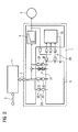
- 1 shows a drive controller 1 which is to be controlled Drive, namely a motor 2, is connected. According to 1 is the drive controller 1 via a bus connection 3 connected to a higher-level automation device 4. Via the bus connection 3, the drive controller 1 and the Automation device 4 Exchange data.
- FIG 1 shows that the higher-level automation device 4 via an internet connection 5 with a is connected to another automation device 6 and via this Internet connection 5 with the automation device 6 can exchange data.
- FIG 1 continues shows, but can also the drive controller 1 as such an Internet connection 7 with the further automation device 6 be connected. In this case, the drive controller 1 immediately without interposing the parent Automation device 4 with the automation device 6 Exchange data.
- the motor 2 should be in real time be managed.
- Essential for the control of the engine 2 required real-time basic functions of the drive controller 1 are in a first function block 8 of the drive controller 1 filed.
- the drive controller 1 for example a current control or speed control for the motor 2 act.
- These real-time basic functions of the drive controller 1 are permanently needed to control the motor 2 and are machine-specific or customer-specific As a rule, requirements are largely independent.
- the Real-time basic functions are therefore in the first function block of the drive controller 1 permanently installed.
- the drive controller 1 in addition to the permanently installed real-time basic functions further functions realized. These are so-called Real-time additional functions that, on the one hand, do not have the entire operating time of the engine 2 are required and on the other hand machine-specific and customer-specific Requirements are dependent.
- the drive controller 1 also has such real-time additional functions in addition to real-time basic functions
- the drive controller 1 has a second one Function block 9.
- the second function block 9 are one or more real-time additional functions if necessary during the operation of the controller and thus during execution of the real-time basic functions can be loaded.
- the real-time additional functions from the higher-level automation device 4 provided and via the bus connection 3 into the second function block 9 Loading can also or any real-time add function the internet connection 5 from the further automation device 6 load and then via bus connection 3 to the second function block 9 passed.
- the real-time additional functions from the automation device 6 provided and over the Internet connection 7 directly from the drive controller 1 in the second Function block 9 can be loaded.
- FIG. 1 illustrates the interaction between real-time basic functions of controller 1 and real-time additional functions using a diagnostic tool as an example.
- the first function block 8 permanently installed Real-time basic functions of the drive controller 1 filed.
- This is, for example, the current control or drive control of the drive controller 1.
- drive controller 1 in a third function block 10 also machine-independent and customer-independent diagnostic functions permanently integrated and thus permanently installed his.
- machine-independent or customer-specific Diagnostic functions are, for example, one Trace function or FFT function.
- a trace function are internal signals of the drive controller in one equidistant time clock can be recorded.
- An FFT function allows it, from these recorded using the trace function A frequency response analysis.
- the third function block 10 of the drive controller 1 permanently installed diagnostic tools, of course on data from the first function block 8, namely the real-time basic functions, access. This is shown in FIG Arrows 11 visualized.
- controller 1 is now in addition to the machine-specific and customer-specific functions in the first and where appropriate third function block 8 or 10 of the drive controller 1 are permanently installed, but others are machine-specific and thus perform customer-specific diagnostic functions, this is how they are, as already mentioned above, during operation of drive controller 1 and thus during execution the real-time basic functions without interrupting them in the second function block 9 can be reloaded.
- the machine-specific ones or customer-specific real-time additional functions that in the second function block 9 can be loaded during operation of the controller and thus during the execution of the real-time basic functions reloadable in the second function block 9.
- the execution of those permanently installed in the first function block 8 Real-time basic functions and, if necessary, execution the machine-independent installed in the third function block 10 Diagnostic tools are therefore used when reloading the machine-specific real-time additional functions in the second function block 9 is not affected.
- FIG 1 illustrates, are to execute the in the second function block 9 reloadable real-time additional functions, however Interfaces between the first function block 8 and the second function block 9 and the third function block 10 and the second function block 9 required.
- a runtime monitoring device 18 is to be made possible available.
- the runtime monitoring device 18 ensures that those running on the drive controller 1 as standard cyclic functions, i.e. the real-time basic functions of the first function block 8 and possibly the machine-independent diagnostic functions of the third function block 10, due to the computing time requirements of the reloadable Real-time additional functions of the second function block 9 are not be affected.
- the runtime monitoring device determines 18 from the or each real-time additional function of the function block 9 required computing time, where if the computing time required by the or each additional real-time function exceeds a predetermined reference time that or any additional real-time function is canceled.
- the reference time is one at commissioning of the controller 1 defined or parameterized, maximum permissible computing time for those that can be reloaded later Real-time additional functions.
- 1 a so-called empty function installed.
- This empty function consumes the maximum parameterized during commissioning permissible computing time of the real-time additional functions, however without perform an actual function.
- Commissioning the drive controller 1 With this empty function it ensures that it is reloaded the real-time additional function in the second function block 9 there are no computing time problems.
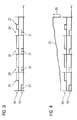
- a first task 19 is a Real-time basic function, in a second task 20 by one reloadable real-time additional function.
- Task 19 of the real-time basic function is cyclically within a given Cycles activated and processed.
- Blocks 21 visualize the used by the real-time basic function during a cycle Computing time.
- Task 19 of the real-time basic function has a higher priority than task 20 of the real-time additional function.
- 3 shows that task 20 of the Real-time additional function at a point in time 22 within the the first cycle shown is started, for which the Task 19 of the real-time basic function has already been processed.
- the task 20 of the real-time additional function is deactivated as long as until task 19 of the real-time basic function within of the second cycle could be processed. Only, the real-time additional function is reactivated. this will executed cyclically as many times in succession, up to a point in time 23 the task 20 of the real-time additional function is ended can.
- the arrows 24 in FIG. 3 illustrate the interruption the task 20 of the real-time additional function by the higher priority Task 19 of the real-time basic function.
- the runtime monitoring device 18 preferably several Timer.
- the timers can be caused by software interrupts and / or hardware interrupts controlled or started and be stopped.
- the timers are not in detail shown.
- a first timer becomes when a is called cyclically reloadable real-time additional function by a corresponding Software interrupt started at time 22 and on End of the corresponding task at time 23 also stopped a software interrupt. This first timer serves accordingly, the determination of the gross computing time of task 20 reloaded real-time additional function.
- the net computing time determined is according to the invention with the configured reference time, i.e. the maximum permissible computing time for the reloadable real-time additional function compared. If this reference time is exceeded by the net computing time the reloadable real-time additional function canceled and a corresponding error message from drive controller 1 generated.
- This ensures that the Functionality of the real-time basic functions through the integration the reloadable real-time additional functions during the Operation of the controller and during the execution of the Real-time basic functions are not affected.
- As well can determine the calculated gross computing time of the reloaded real-time additional function with a reference value for the gross term be compared. This ensures that a real-time additional function to be reloaded is safely processed can be.
- a storage space access monitoring device 27 available.
- the storage space access monitoring device 27 provides sure that reloaded into the second function block 9 Real-time additional functions not on memory addresses or Access memory areas that are available in function block 8 fixed real-time basic functions are reserved. Faulty memory accesses during the operation of the Controller 1 and thus while executing the real-time basic functions reloaded real-time additional function are avoided.
- the memory monitoring device 27 monitors all memory addresses for this accessed by the reloaded real-time additional function becomes. Do these memory addresses not match the specified ones? Reference memory addresses match that for the real-time additional functions are reserved, the reloaded Real-time additional function canceled and from drive controller 1 a corresponding error message is generated.
- the space access monitor manages 27 therefore two defined Storage areas.
- a first defined memory area is only for the real-time basic functions of the first function block 8 accessible.
- a second memory area is from the real-time basic functions and additionally the reloadable ones Real-time additional functions of the second function block 9 addressable. There are copies in this second memory area of the variables of the real-time basic functions.
- the drive controller 1 Data exchange between permanently installed, machine-independent Functions such as the real-time basic functions of the first function block 8 and the machine-independent Diagnostic functions of the third function block 10, and the reloadable, machine-specific real-time additional functions of the second function block 9 via so-called binector / connector connections realized.
- 2 shows several Binector / connector connections 28. Each of these binector / connector connections consists of a signal source 29 and one corresponding signal sink 30. So, depending on the Direction of data flow, either the second function block 9 for the reloadable real-time additional functions or the function blocks 8 and 10 for the permanently installed Functions of the drive controller 1 signal sources 29 or signal sinks 30 assigned.
- such binector / connector connections are required 28 when reloading a real-time additional function Restrictions installed.
- no binector / connector connections to be separated which when installing the Drive controller 1 have been set up. Otherwise, could be due to a faulty, reloading real-time additional function the functionality of the parallel real-time basic functions of the controller 1 impaired become.
- the reloadable real-time additional function no signals in the parallel real-time basic function be fed. This would also Influence on the functionality of the real-time basic function taken.
- This limitation is visualized in FIG. that a binector / connector connection 31, the one such additive overlay would be crossed out is.
- the real-time additional functions are both via a bus connection 3 from a higher-level automation device 4 and an Internet connection 5 or 7 from one further automation device 6 loadable.
- the reloadable additional functions from the permanently installed basic functions or basic functions of the Decoupled drive controller. Because only needed temporarily Additional functions of controller 1 reloaded if necessary and already loaded ones that are no longer needed Additional functions can be overwritten for the drive controller 1 hardware resources, e.g. storage space, be saved.
- a drive controller are provided in the one hand only machine-independent and customer-specific basic functions and if necessary diagnostic functions are integrated and in the on the other hand machine-specific and customer-specific additional functions can be reloaded if necessary without the operation of the controller 1 or its basic functions should be interrupted. This opens up many possibilities for the integration of machine-specific diagnostic functions, Maintenance functions or other updates for the drive controller 1.
Landscapes
- Physics & Mathematics (AREA)
- General Physics & Mathematics (AREA)
- Engineering & Computer Science (AREA)
- Automation & Control Theory (AREA)
- Programmable Controllers (AREA)
- Testing And Monitoring For Control Systems (AREA)
Applications Claiming Priority (2)
| Application Number | Priority Date | Filing Date | Title |
|---|---|---|---|
| DE10243856 | 2002-09-20 | ||
| DE10243856A DE10243856B4 (de) | 2002-09-20 | 2002-09-20 | Regler und Verfahren zum Betreiben eines Reglers |
Publications (3)
| Publication Number | Publication Date |
|---|---|
| EP1400877A2 true EP1400877A2 (fr) | 2004-03-24 |
| EP1400877A3 EP1400877A3 (fr) | 2004-12-22 |
| EP1400877B1 EP1400877B1 (fr) | 2007-11-07 |
Family
ID=31896259
Family Applications (1)
| Application Number | Title | Priority Date | Filing Date |
|---|---|---|---|
| EP03020280A Expired - Lifetime EP1400877B1 (fr) | 2002-09-20 | 2003-09-08 | Régulateur et procédé pour faire fonctionner un régulateur |
Country Status (3)
| Country | Link |
|---|---|
| US (1) | US7146470B2 (fr) |
| EP (1) | EP1400877B1 (fr) |
| DE (2) | DE10243856B4 (fr) |
Cited By (3)
| Publication number | Priority date | Publication date | Assignee | Title |
|---|---|---|---|---|
| WO2007006774A1 (fr) * | 2005-07-08 | 2007-01-18 | Lenze Drive Systems Gmbh | Memoire a alignement des donnees a partir d'un regulateur d'entrainement d'une machine et destinee a ce regulateur d'entrainement |
| WO2009112130A1 (fr) * | 2008-03-11 | 2009-09-17 | Sew-Eurodrive Gmbh & Co. Kg | Dispositif pour commander une installation et procédé pour installer et piloter la commande d'une installation |
| EP2247987A1 (fr) * | 2008-02-25 | 2010-11-10 | Endress + Hauser Process Solutions AG | Procédé pour faire fonctionner un appareil de terrain |
Families Citing this family (13)
| Publication number | Priority date | Publication date | Assignee | Title |
|---|---|---|---|---|
| DE102004045196A1 (de) * | 2004-09-17 | 2006-03-30 | Siemens Ag | Verfahren zur Anpassung von Parametern einer Steuerungs- oder Regelungseinrichtung |
| DE102005048037A1 (de) * | 2005-10-07 | 2007-04-12 | Robert Bosch Gmbh | Verfahren zur Steuerung/Regelung wenigstens einer Task |
| JP2007156824A (ja) * | 2005-12-05 | 2007-06-21 | Nec Electronics Corp | プロセッサシステム、タスク制御方法 |
| US8856753B2 (en) * | 2008-04-18 | 2014-10-07 | International Business Machines Corporation | Granular measurement of processor performance in executing sections of software code |
| US8145692B2 (en) * | 2008-05-29 | 2012-03-27 | Harris Corporation | Digital generation of an accelerated or decelerated chaotic numerical sequence |
| KR101633484B1 (ko) * | 2009-12-11 | 2016-06-27 | 삼성전자주식회사 | 선택적 부팅 방법 및 이를 이용한 방송 수신 장치 |
| US20120072632A1 (en) * | 2010-09-17 | 2012-03-22 | Paul Kimelman | Deterministic and non-Deterministic Execution in One Processor |
| KR101254875B1 (ko) * | 2011-05-18 | 2013-04-15 | 삼성에스디아이 주식회사 | 배터리 팩 관리시스템 |
| US10394640B2 (en) * | 2016-02-25 | 2019-08-27 | Infineon Technologies Austria Ag | Requirement runtime monitor using temporal logic or a regular expression |
| DE102016107527A1 (de) | 2016-04-22 | 2017-10-26 | Beckhoff Automation Gmbh | Echtzeitumgebung und speicherprogrammierbare Steuerung |
| US10353364B2 (en) * | 2016-05-03 | 2019-07-16 | Schneider Electric Systems Usa, Inc. | Application specific field device for process control system |
| DE102018133058A1 (de) | 2018-12-20 | 2020-06-25 | Beckhoff Automation Gmbh | Verfahren zum steuern eines automatisierungsprozesses in echtzeit |
| US12321739B2 (en) * | 2021-04-22 | 2025-06-03 | STMicroelectronics (Grand Ouest) SAS | Microcontroller, computer program product, and method for adding an additional function to a computer program |
Family Cites Families (14)
| Publication number | Priority date | Publication date | Assignee | Title |
|---|---|---|---|---|
| US5214768A (en) * | 1989-11-01 | 1993-05-25 | E-Systems, Inc. | Mass data storage library |
| JP2520544B2 (ja) | 1991-09-26 | 1996-07-31 | インターナショナル・ビジネス・マシーンズ・コーポレイション | タスクのオ―バ―ラン状態を監視する方法及びタスク実行サイクルのオ―バ―ランを検出する装置 |
| DK0607493T3 (da) * | 1993-01-18 | 1999-08-30 | Siemens Ag | Realtidsstyresystem |
| DE19549154A1 (de) * | 1995-12-29 | 1997-07-10 | Elmeg | Steuereinheit für einen einzelnen Verbraucher |
| US6263487B1 (en) * | 1996-01-17 | 2001-07-17 | Siemens Ag | Programmable controller |
| US5754424A (en) * | 1996-02-27 | 1998-05-19 | Melvin; Kenneth P. | System and method for controlling processes |
| US6256714B1 (en) * | 1998-09-02 | 2001-07-03 | Sharp Laboratories Of America, Inc. | Computer system with efficient memory usage for managing multiple application programs |
| DE19835416A1 (de) * | 1998-08-05 | 2000-02-17 | Siemens Ag | Verfahren und Einrichtung zur Inbetriebsetzung von Anlagen der Grundstoffindustrie |
| US6397385B1 (en) * | 1999-07-16 | 2002-05-28 | Excel Switching Corporation | Method and apparatus for in service software upgrade for expandable telecommunications system |
| US6850973B1 (en) * | 1999-09-29 | 2005-02-01 | Fisher-Rosemount Systems, Inc. | Downloadable code in a distributed process control system |
| DK176631B1 (da) * | 1999-12-20 | 2008-12-08 | Danfoss Drives As | Programmering af en motorstyring |
| US6691249B1 (en) * | 2000-03-22 | 2004-02-10 | Agilent Technologies, Inc. | Probabilistic diagnosis, in particular for embedded and remote applications |
| DE10065401A1 (de) * | 2000-12-27 | 2003-03-06 | Siemens Ag | Automatisierungssystem |
| US20030018892A1 (en) * | 2001-07-19 | 2003-01-23 | Jose Tello | Computer with a modified north bridge, security engine and smart card having a secure boot capability and method for secure booting a computer |
-
2002
- 2002-09-20 DE DE10243856A patent/DE10243856B4/de not_active Expired - Fee Related
-
2003
- 2003-09-08 DE DE50308527T patent/DE50308527D1/de not_active Expired - Lifetime
- 2003-09-08 EP EP03020280A patent/EP1400877B1/fr not_active Expired - Lifetime
- 2003-09-12 US US10/661,280 patent/US7146470B2/en not_active Expired - Fee Related
Cited By (3)
| Publication number | Priority date | Publication date | Assignee | Title |
|---|---|---|---|---|
| WO2007006774A1 (fr) * | 2005-07-08 | 2007-01-18 | Lenze Drive Systems Gmbh | Memoire a alignement des donnees a partir d'un regulateur d'entrainement d'une machine et destinee a ce regulateur d'entrainement |
| EP2247987A1 (fr) * | 2008-02-25 | 2010-11-10 | Endress + Hauser Process Solutions AG | Procédé pour faire fonctionner un appareil de terrain |
| WO2009112130A1 (fr) * | 2008-03-11 | 2009-09-17 | Sew-Eurodrive Gmbh & Co. Kg | Dispositif pour commander une installation et procédé pour installer et piloter la commande d'une installation |
Also Published As
| Publication number | Publication date |
|---|---|
| DE10243856B4 (de) | 2004-09-30 |
| EP1400877A3 (fr) | 2004-12-22 |
| DE50308527D1 (de) | 2007-12-20 |
| DE10243856A1 (de) | 2004-04-15 |
| EP1400877B1 (fr) | 2007-11-07 |
| US20040059867A1 (en) | 2004-03-25 |
| US7146470B2 (en) | 2006-12-05 |
Similar Documents
| Publication | Publication Date | Title |
|---|---|---|
| DE10243856B4 (de) | Regler und Verfahren zum Betreiben eines Reglers | |
| EP2062105B1 (fr) | Système et procédé de fonctionnalisation en fonction du besoin de dispositifs de commande/régulation | |
| EP1422629B1 (fr) | Procédé pour la configuration automatique de l'affichage de paramètres de machine-outils ou de machines de production | |
| DE102015004932B4 (de) | Simulationsvorrichtung für mehrere Roboter | |
| DE69114905T2 (de) | Verfahren und System zum Optimieren des Abschaltens in Systemen aus programmierbaren Vorrichtungen. | |
| DE102006028992A1 (de) | Elektronische Steuervorrichtung | |
| DE102006028695B4 (de) | Elektronisches Steuersystem mit Fehlfunktionsüberwachung | |
| EP1479003B1 (fr) | Procede et dispositif de commande d'une unite fonctionnelle d'un vehicule automobile | |
| EP2698678A2 (fr) | Technique de configuration pour un appareil de commande avec des applications communiquant entre elles | |
| EP3080668B1 (fr) | Procédé destiné à influencer un programme de commande d'un appareil de commande | |
| EP0898745B1 (fr) | Procede pour controler la fiabilite de fonctionnement d'une unite de calcul | |
| DE10309891B4 (de) | Elektronische Fahrzeugsteuervorrichtung mit einer Vielzahl von Mikrocomputern zum Implementieren einer Mikrocomputerüberwachungsfunktion | |
| DE19750026A1 (de) | Verfahren und Vorrichtung zum Betreiben von Steuereinrichtungen für ein Fahrzeug | |
| WO1998028687A1 (fr) | Procede pour controler la fiabilite de fonctionnement d'une unite de calcul | |
| EP0799441B1 (fr) | Procede de commande de processus techniques | |
| EP1548527A1 (fr) | Commande pour une machine-outil ou machine de production | |
| WO2003069424A2 (fr) | Limitation du temps de reaction d'un processus logiciel | |
| DE10331872A1 (de) | Verfahren zur Überwachung eines technischen Systems | |
| EP1119801A1 (fr) | Procede d'exploitation d'un systeme d'automatisation | |
| EP1733284B1 (fr) | Commande d'execution de fonctions sur des appareils qui interagissent les uns avec les autres | |
| EP1179428B1 (fr) | Procédé et dispositif pour exécuter des pas d'un procédé | |
| DE102020201002A1 (de) | Maschinensteuervorrichtung | |
| DE19946096A1 (de) | Steuergerät, insbesondere für ein Kraftfahrzeug | |
| WO2005041041A2 (fr) | Procede et dispositif pour mesurer le temps de parcours de fonctions | |
| DE10254009A1 (de) | Verfahren und Datennetzwerk zur automatischen Konfiguration von Regelungen und Steuerungen von Werkzeug- oder Produktionsmaschinen |
Legal Events
| Date | Code | Title | Description |
|---|---|---|---|
| PUAI | Public reference made under article 153(3) epc to a published international application that has entered the european phase |
Free format text: ORIGINAL CODE: 0009012 |
|
| AK | Designated contracting states |
Kind code of ref document: A2 Designated state(s): AT BE BG CH CY CZ DE DK EE ES FI FR GB GR HU IE IT LI LU MC NL PT RO SE SI SK TR |
|
| AX | Request for extension of the european patent |
Extension state: AL LT LV MK |
|
| PUAL | Search report despatched |
Free format text: ORIGINAL CODE: 0009013 |
|
| AK | Designated contracting states |
Kind code of ref document: A3 Designated state(s): AT BE BG CH CY CZ DE DK EE ES FI FR GB GR HU IE IT LI LU MC NL PT RO SE SI SK TR |
|
| AX | Request for extension of the european patent |
Extension state: AL LT LV MK |
|
| 17P | Request for examination filed |
Effective date: 20050120 |
|
| AKX | Designation fees paid |
Designated state(s): DE FR GB |
|
| GRAP | Despatch of communication of intention to grant a patent |
Free format text: ORIGINAL CODE: EPIDOSNIGR1 |
|
| GRAS | Grant fee paid |
Free format text: ORIGINAL CODE: EPIDOSNIGR3 |
|
| GRAA | (expected) grant |
Free format text: ORIGINAL CODE: 0009210 |
|
| AK | Designated contracting states |
Kind code of ref document: B1 Designated state(s): DE FR GB |
|
| REG | Reference to a national code |
Ref country code: GB Ref legal event code: FG4D Free format text: NOT ENGLISH |
|
| RIN2 | Information on inventor provided after grant (corrected) |
Inventor name: HEINEMANN, GERHARD, DR. |
|
| GBT | Gb: translation of ep patent filed (gb section 77(6)(a)/1977) |
Effective date: 20071107 |
|
| REF | Corresponds to: |
Ref document number: 50308527 Country of ref document: DE Date of ref document: 20071220 Kind code of ref document: P |
|
| ET | Fr: translation filed | ||
| PLBE | No opposition filed within time limit |
Free format text: ORIGINAL CODE: 0009261 |
|
| STAA | Information on the status of an ep patent application or granted ep patent |
Free format text: STATUS: NO OPPOSITION FILED WITHIN TIME LIMIT |
|
| 26N | No opposition filed |
Effective date: 20080808 |
|
| PGFP | Annual fee paid to national office [announced via postgrant information from national office to epo] |
Ref country code: GB Payment date: 20090910 Year of fee payment: 7 |
|
| PGFP | Annual fee paid to national office [announced via postgrant information from national office to epo] |
Ref country code: DE Payment date: 20091120 Year of fee payment: 7 |
|
| GBPC | Gb: european patent ceased through non-payment of renewal fee |
Effective date: 20100908 |
|
| REG | Reference to a national code |
Ref country code: FR Ref legal event code: ST Effective date: 20110531 |
|
| REG | Reference to a national code |
Ref country code: DE Ref legal event code: R119 Ref document number: 50308527 Country of ref document: DE Effective date: 20110401 |
|
| PG25 | Lapsed in a contracting state [announced via postgrant information from national office to epo] |
Ref country code: DE Free format text: LAPSE BECAUSE OF NON-PAYMENT OF DUE FEES Effective date: 20110401 Ref country code: FR Free format text: LAPSE BECAUSE OF NON-PAYMENT OF DUE FEES Effective date: 20100930 |
|
| PG25 | Lapsed in a contracting state [announced via postgrant information from national office to epo] |
Ref country code: GB Free format text: LAPSE BECAUSE OF NON-PAYMENT OF DUE FEES Effective date: 20100908 |
|
| PGFP | Annual fee paid to national office [announced via postgrant information from national office to epo] |
Ref country code: FR Payment date: 20091008 Year of fee payment: 7 |