EP1400885A2 - Aktive Schwingungssteuervorrichtung - Google Patents
Aktive Schwingungssteuervorrichtung Download PDFInfo
- Publication number
- EP1400885A2 EP1400885A2 EP03255684A EP03255684A EP1400885A2 EP 1400885 A2 EP1400885 A2 EP 1400885A2 EP 03255684 A EP03255684 A EP 03255684A EP 03255684 A EP03255684 A EP 03255684A EP 1400885 A2 EP1400885 A2 EP 1400885A2
- Authority
- EP
- European Patent Office
- Prior art keywords
- vibrations
- actuator
- source
- control system
- sensor
- Prior art date
- Legal status (The legal status is an assumption and is not a legal conclusion. Google has not performed a legal analysis and makes no representation as to the accuracy of the status listed.)
- Granted
Links
Images








Classifications
-
- G—PHYSICS
- G05—CONTROLLING; REGULATING
- G05D—SYSTEMS FOR CONTROLLING OR REGULATING NON-ELECTRIC VARIABLES
- G05D19/00—Control of mechanical oscillations, e.g. of amplitude, of frequency, of phase
- G05D19/02—Control of mechanical oscillations, e.g. of amplitude, of frequency, of phase characterised by the use of electric means
-
- B—PERFORMING OPERATIONS; TRANSPORTING
- B64—AIRCRAFT; AVIATION; COSMONAUTICS
- B64C—AEROPLANES; HELICOPTERS
- B64C27/00—Rotorcraft; Rotors peculiar thereto
- B64C27/001—Vibration damping devices
- B64C2027/004—Vibration damping devices using actuators, e.g. active systems
Definitions
- This invention relates to an active vibration control system useful, for example, to control vibrations caused by the rotor, gear box, and engine assembly of a helicopter and to isolate structures from sources of vibration.
- Vibrations can cause unwanted noise, material fatigue, and even catastrophic failure of systems.
- active vibration control systems are sometimes employed.
- the control system detects the amplitude and frequency of the vibrations emanating from a vibrating source and attempts to cancel them out by imparting canceling forces.
- vibrations of the rotor, gear box, and engine assembly of a helicopter are controlled by a system including accelerometers on the helicopter fuselage which detect vibrations; actuators between the fuselage and the rotor, gear box, and engine assembly; and a processing system which drives the actuators in response to the accelerometer signals.
- a system including accelerometers on the helicopter fuselage which detect vibrations; actuators between the fuselage and the rotor, gear box, and engine assembly; and a processing system which drives the actuators in response to the accelerometer signals.
- such a system is based on the premise that the vibrations are periodic comprising one or more steady sinusoidal behaviors that are summed together. In truth, they are not periodic: during each revolution of the rotor, the amplitude of the vibrations change, and as between successive rotations, the vibrations are not the same even when the rotor speed and airspeed remain constant. The result is that present systems do not always sufficiently cancel the resulting vibrations when employed with sources of vibrations exhibiting irregular chaotic behavior.
- This invention results from the realization that the computational complexity of the prior art active vibration isolation systems can be reduced by a single accelerometer attached to the source of vibrations, a correction subsystem which estimates the output of that accelerometer in the absence of the controlling vibrations caused by the actuators and which drives the actuators according to the estimate thereby eliminating the need for numerous accelerometers on the structure and that even chaotic vibrations can be controlled a) by relying on the fact that they are deterministic and b) by employing a state space predictor which analyzes variations in the accelerometer's signal to better drive the actuators to control even chaotic vibrations.
- This invention features an active vibration control system comprising a sensor responsive to a source of vibration which provides an output signal representative of the vibrations; at least one actuator positioned to impart canceling vibrations to the source of vibrations based on an input signal; a correction subsystem responsive to the actuator for estimating the sensor output in the absence of the canceling vibrations and which outputs a corrected output signal representative only of the vibrations emanating from the source; and a state space predictor responsive to the corrected output signal for determining the input signal to the actuator based on variations in the corrected output signal to better control vibrations especially in chaotic systems.
- the sensor is typically an accelerometer which is physically connected to the source of vibration.
- the actuator may be an electro-hydraulic actuator.
- the source of vibrations is the rotor, gear box, and engine assembly of helicopter
- the sensor is an accelerometer attached to the gear box
- the actuator is positioned between the airframe of the helicopter and the rotor, gear box, and engine assembly.
- the improved active vibration control system of this invention includes a source of vibrations, a structure which is impacted by the source of vibrations, a sensor or sensors connected to the structure, an actuator or actuators positioned to impart canceling vibrations to the source; and an analyzer/control subsystem responsive to the sensor or sensors for driving the actuator or actuators.
- the improvement comprises a sensor to be positioned to detect vibrations directly from the source; and a software package including: a correction subsystem responsive to the actuator for estimating the sensor output in the absence of the canceling vibrations and which outputs a corrected output signal representative only of the vibrations emanating from the source; and a state space predictor responsive to the corrected output signal for determining the input signal to the actuator based on variations in the corrected output signal to better control vibrations especially in a chaotic system.
- the active vibration control system of this invention includes a sensor responsive to a source of vibration which provides an output signal representative of the vibrations; at least one actuator positioned to impart canceling vibrations to the source of vibrations based on an input signal; and a correction subsystem responsive to the actuator for estimating the sensor output in the absence of the canceling vibrations and which outputs a corrected output signal representative only of the vibrations emanating from the source.
- a sensor is responsive to a source of vibration which provides an output signal representative of the vibrations.
- At least one actuator is positioned to impart canceling vibrations to the source of vibrations based on an input signal.
- a state space predictor is responsive to the output signal for determining the input signal to the actuator based on variations in the output signal to better control vibrations especially in chaotic systems.
- the active vibration control system of this invention features sensor 10, Fig. 1 responsive to a source of vibration.
- sensor 10 is an accelerometer attached directly to the gear box of the rotor, gear box, and engine assembly 12 of helicopter 14.
- sensor 10 is an accelerometer attached directly to the gear box of the rotor, gear box, and engine assembly 12 of helicopter 14.
- Typically four electro-hydraulic actuators are used to impart canceling vibrations to the source of vibrations, engine assembly 12.
- two actuators 18 and 20 are shown between rotor, gear box, and engine assembly 12 and airframe 30, the structure to be isolated from vibrations caused by the rotor gear box, and the engine assembly of helicopter 14.
- accelerometers 40, 42, 44, and 46 are used as the input to controller 70 on board helicopter 14 which drives actuators 18 and 20.
- controller 70 on board helicopter 14 which drives actuators 18 and 20.
- the signal from accelerometer 10 depends not only on the vibrations emanating from source 12, but also on the contribution from actuators 18 and 20 affecting the vibrations emanating from source 12.
- a correction subsystem which is a component of controller 70 uniquely estimates the output of sensor 10 in the absence of canceling vibrations caused by actuators 18 and 20 and, in response, provides a corrected output signal representative of only the vibrations emanating from the source of vibrations 12.
- a state space predictor is employed as part of controller 70. Its input is the corrected output signal from accelerometer 10 representing only the vibrations from source 12 and not the vibrations caused by actuators 18 and 20.
- the state space predictor of this invention is modeled after the work of Abarbanel, H.D.I., Brown, R., Sidorowich, J.J., and Tsimring, L.S., "The Analysis of Observed Chaotic Data in Physical Systems," Reviews of Modern Physics, v 65, No. 4, pp. 1331-1392, October 1993; Abarbanel, H.D.I., Analysis of Observed Chaotic Data, Springer-Verlag, 1996; Rulkov, N.F., Tsimring, L.S., and Abarbanel, H.D.I., "Tracking Unstable Obits in Chaos Using Dissipative Feedback Control," Physical Review E, v 50, No. 1, pp.
- gear box accelerometer 10 is shown as are four actuators 18, 20, 22, and 24.
- Ten airframe accelerometers 40-58 are also shown but not required. Instead, the output of these accelerometers placed on the structure (here the airframe) to be isolated from vibrations are used for optimization only.
- the correction subsystem of controller 70, Fig. 1 is shown at 100 as the proxy gear box correction block.
- the state space predictor is shown at 102. It is to be understood that both of these "components" are actually software programs operating on a processor as explained infra .
- the subject invention is useful for actively damping any source of vibrations.
- the following disclosure is directed to a specific implementation on a helicopter in order to show test results and one preferred embodiment of the subject invention.
- the invention relates to the use of active control to reduce the vibrations in helicopters, but can be extended and applied to a broad range of additional applications, including vibration reduction in fixed wing aircraft, vibration control in mobile and fixed rotating machinery, and active noise control.
- vibration driving force is irregular, because the future driving force is not simply a delayed copy of an earlier driving force.
- Using the assumption of periodicity with such systems can result in significant control errors, limiting the extent to which the vibration can be reduced.
- vibration driving forces that are low dimensional and chaotic, i.e., deterministic but inherently unstable. Because of their inherent instability, chaotic dynamics can only be predicted for short periods of time that are often sufficient for purposes of control.
- the inventions described here relate to the application of the methods of nonlinear dynamics to reduce structural vibration and/or noise.
- Helicopter vibrations are chaotic and comprise a fundamental vibration at the blade passing frequency, plus several harmonics, all of which are modulated in amplitude in an irregular fashion. These vibrations are reasonably well behaved, in that they are low dimensional, can be predicted for short periods of time, have identifiable unstable periodic orbits, etc.
- "higher harmonic control” HHC was used to minimize vibrations. HHC is different from vibration isolation, in that the vibration is attacked at its source, the helicopter rotor, by "dithering" the swashplate of the rotor appropriately with each blade passing.
- HHC has been associated with damage to rotor hub components, and currently is not being pursued as a primary candidate approach for helicopter vibration control.
- the rotor assembly comprising the rotor, hub, gearbox, and engines, is considered separate from the airframe of the helicopter.
- Actuators are installed between the rotor assembly and airframe, and driven in such a way as to minimize the transmission of vibration from the rotor assembly to the airframe.
- Multiple accelerometers mounted on the airframe monitor the vibration, providing a basis for control optimization.
- the existing ACSR system used in production helicopters utilizes an adaptive linear feed-forward control algorithm that basically assumes that the rotor vibration is a steady periodic.
- the subject invention employs dynamical analysis methods to enhance the performance of ACSR, largely as a software upgrade to the existing ACSR system.
- the demonstration control system is illustrated schematically in Figure 2.
- the overall control system is broken into two basic processes, the "front office process” 200 and the "back office process” 202.
- the front office process 200 is a highly efficient transaction-based process that is responsible for the instant-by-instant vibration control.
- Back office process 202 builds and modifies the settings for the front office process. Since the front office process is normally sufficient to provide desirable control accuracy with relatively fixed settings (proxy gearbox correction model, state space predictor model, and control model), the back office process does not need to work in real time. It is effectively more “contemplative", examining areas in which the system's performance departs from ideal, attributing the source of error, and updating the models as appropriate. Many aspects of the back office process are currently implemented in the existing ACSR algorithm. Still, the distinction between the front and back office processes is fundamentally different from the existing ACSR system, which integrates the functions of the front and back office processes into a single control process that operates at all times.
- One novel aspect of the new control system is the use of accelerometer 10 mounted on the gearbox which serves as a "proxy" for the rotor vibration driving force.
- the actuator 18, 20, 22, and 24 demand signals are scheduled according to the vibration state estimated from this single-point measurement.
- a tri-axial accelerometer could also be used to monitor the rotor vibration in three orthogonal directions. This would allow tracking variations in the rotor vibration that occur in different flight conditions and during dynamic maneuvers.
- the existing ACSR system monitors all 10 of the airframe accelerometers at all times to estimate the system condition.
- the primary component of helicopter vibration occurs at the blade passing frequency, so the system illustrated in Figure 2 is designed to minimize the airframe response at this frequency. This does not limit the concept to single-frequency control, as multiple-frequency control is an obvious extension of the technique. Further, arbitrary-frequency control should be feasible as well.
- the system predicts the blade-passing-frequency component of the rotor driving force a short period into the future, just long enough to permit implementing a suitable actuator forcing function. This prediction is performed using state space predictor 102, which uses several sequential values from the gearbox accelerometer 10 to find the current condition of the vibration in state space and estimate the corresponding vibration component. The resulting information is then used to generate the actuator demand signal that will cancel the vibration as well as possible.
- Another novel aspect of this control system is the correction of the gearbox acceleration to determine the proxy rotor vibration.
- the vibration control actuators 18, 20, 22, 24 affect the gearbox vibration, so the observed gearbox response must be corrected to estimate what the vibration would be in the absence of control. This is generally feasible, because each combination of rotor vibration and actuator forces should have a reproducible effect on the gearbox vibration.
- a nonlinear state space is used to determine the proxy vibration from the measured vibration and actual actuator demand signals. This state space is developed through earlier testing with various combinations of actuator forces and rotor vibrations. Desirable accuracy is also achieved using a linear correction. This involves subtracting the effects of each of the actuators from the observed gearbox vibration.
- state space predictor 102 Given the predicted vibration at the blade passing frequency, provided by state space predictor 102, there are numerous methods that can be used to determine the actuator drive signals to minimize the airframe response. The most sophisticated approach involves building a state space look up model that maps the vibration condition to the optimal actuator settings. This model is then be integrated into the state space predictor itself. On the other hand, a simple control matrix is usually sufficient to permit a level of vibration reduction that approaches the limit of controllability of the actuators and the airframe. Between these two levels of sophistication is a control matrix whose coefficients are a function of the amplitude of the rotor vibration. This improves the vibration reduction when the airframe response is more nonlinear, but where the fully non-linear state space model is not called for.
- the airframe 30 is viewed as a body that maps the driving forces acting upon it to the responses of the accelerometers 40-58 mounted on it.
- the airframe state is Y
- its time derivative is a function f of the rotor forcing function R(t) and several actuators 18, 20, 22, and 24 u(t).
- the response of the accelerometers is a function g of airframe state Y.
- the functions f and g are initially assumed to be arbitrary with no assumption that the effects of the rotor driving function and actuator inputs in any way additive.
- Y f(Y, R, u )
- g g(Y)
- Figure 4 shows raw time series data that were recorded for the vertical vibration of the gearbox of an EH-101 helicopter using the output for accelerometer 10, Figs. 1-2.
- This particular flight condition level flight at 140 kias (knots indicated airspeed), is considered the nominal high speed cruise condition for the EH-101, and is typical of many mission profiles.
- These data were collected with the prior ACSR system turned off i.e., with no vibration control.
- Note the vertical scale of Figure 4 is arbitrary. These data were collected at a nominal 4096 Hz, which actually corresponds to exactly 1170.25 samples per rotor rotation. Since the rotor rotational speed is not exactly constant, the sampling is synchronized to rotor position.
- the blade passing frequency is the large-scale low-frequency behavior visible in Figure 4.
- This behavior and behaviors at several harmonics of this fundamental there are very strong high-frequency behaviors that are produced by the engines, gearbox, and attached accessories. These behaviors all occur at frequencies above 200 Hz, while the blade passing frequency is about 17.5 Hz.
- the blade passing frequency is about 17.5 Hz.
- FIR finite impulse response
- IIR infinite impulse response
- a given output value depends solely on N input values (the filter window size), so an arbitrary behavior occurring in the input data persists in the output data for a finite period of time.
- the filter coefficients, the output vector, and a set of initial values for the input vector the input vector can be reconstructed with some accuracy.
- an FIR filter does not really "kill” the dynamics it filters out, but instead “mushes them” into other frequencies.
- Nonlinear dynamicists normally prefer FIR filters for this reason, because they do not want to tamper with the dynamics naturally occurring in the data. By contrast, this is not desirable with the gearbox vibration data, since we simply want to ignore the high frequency behaviors.
- IIR filter 204 Fig. 2 is a bit more complicated:
- the output vector depends on both recent values of the input data and on recent values of the output vector. Being auto-regressive, the response of an IIR filter to a given behavior in the input data persists forever (thus its designation as infinite impulse response). By virtue of its autoregressive nature, having the filter coefficients, the output vector, and a finite amount of information about initial conditions of the input vector does not permit an accurate reconstruction of the input vector. Thus, IIR filters really do "kill" the behaviors they reject.
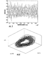
- Figure 5 illustrates the results obtained by filtering the data of Figure 4 with low-pass IIR filter 204, Fig. 2. This clearly eliminated the high-frequency behaviors.
- Figure 5 also reflects the resampling of the Figure 4 data to a different time base.
- the EH-101 helicopter has a blade passing frequency of approximately 17.5 Hz, while the Westland 30 on which the ACSR test rig is based has a frequency of about 22 Hz.
- the blade passing frequency of the EH-101 data is sped up. Rather than increasing it to 22 Hz (which would necessitate a fair amount of bookkeeping for the remainder of the program), 20 Hz was used.
- the data in Figure 5 were resampled to a 2 kHz sampling rate with a 20 Hz blade passing frequency, or 100 samples per blade passing.
- Figure 6 shows a 3-dimensional reconstruction of the data in Figure 5.
- This reconstruction used 5 sec of data (10000 points at 2 kHz) and a reconstruction time delay of 6 msec.
- the blade passing frequency behavior is clearly dominant, being responsible for the largely toroidal character of the attractor.
- this behavior typically would be characterized as noise.
- the variation is highly structured, with neighboring trajectories behaving quite similarly.
- This 3-dimensional graph of the attractor is not actually an unambiguous representation of the dynamics of the data. Although it is not obvious from the graph, there are many places in which trajectories cross. A false nearest neighbors analysis finds that the dynamics are not completely unfolded unless a 5- or 6-dimensional representation is used.
- State space prediction works by identifying a set of points that are near a given point in state space, and characterizing how these points map forward with time. In many cases, particularly if the prediction time is short, it is possible to obtain good predictions using a linear mapping of the neighborhood forward in time.
- the "k-d tree” algorithm is employed to build a database representing the state space as a tree with branches and sub-branches, etc. See Freidman, J.H.; Bentley, J.L.; and Finkle, R.A., "An Algorithm for Finding Best Matches in Logarithimic Expected Time," ACM Transactions on Mathematical Software, V3, No. 3, pp. 209-226, September 1977.
- At the end of each branch is a small box containing one or more data points.
- the algorithm looks first in the box corresponding to the state space location of the point to see if there are other points there.
- the basic functions of the front office process 200 are to identify the rotor input force, identify the 20-Hz component (possibly some time in advance), and apply suitable demand signals to the outputs of actuators 18, 20, 22, and 24.
- gearbox vibration detected by accelerometer 10 is used as a proxy for the rotor input forcing function
- the control actuators 18, 20, 22, and 24 produce forces that affect this vibration.
- the best way to account for this difference is to estimate what the gearbox vibration would be in the absence of control inputs, i.e., to correct the observed gearbox vibration to produce the gearbox vibration that is the best proxy for the rotor input.
- the gearbox of helicopter 14, Fig. 1 is largely a rigid mass with respect to forces occurring at rotor input frequencies, so it is possible that the gearbox accelerometer 10 response can be viewed as a simple linear sum of responses to each of the input forces. It turns out that this is a pretty fair assumption.
- Figure 8 illustrates an example for tests with combined 20 and 60 Hz control of recorded flight vibrations.
- the points marked with circles represent the actual response to the head shaker input, i.e., the response without control that is the objective.
- the large amplitude solid curve is the estimated proxy gearbox vibration determined by proxy gear box correction subsystem 100, Fig. 2 by subtracting the response to each of the four ACSR actuators 18, 20, 22, and 24 from the response to all actuators.
- the small amplitude curve is the difference between the other two.
- the RMS error is 13.0 percent of the standard deviation of the actual vibration.
- proxy gearbox correction subsystem 100 Fig. 2
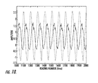
- Fig. 2 Another aspect of proxy gearbox correction subsystem 100, Fig. 2 is the amplitude and phase relationships between the gearbox vibration with and without control, shown in Figure 10.
- the gearbox response with control is of lower amplitude (by 48.0%) than without control, and lags the response without control by close to 60°.
- the amplitude and phase characteristics of the proxy gearbox correction can be important to the stability of using this correction in an on-line control system. That is, using the known actuator signals to correct the observed gearbox vibration to estimate the proxy gearbox vibration can affect the stability of the overall control system.
- FIG. 11 shows a schematic of the simulation used.
- the sine wave generator 300 represents the gearbox response to the rotor input force (G r ).
- G x added to G r is a model of the actuator influence on the gearbox vibration. The sum of these is the total gearbox response, measured with accelerometer 10, Fig. 2 is termed G.
- the three blocks in the upper part of the right side of the figure are a model of the proxy gearbox correction, called G p .
- the scope block 302 on the schematic displays graphs of the key signals for quick confirmation of the system behavior.
- the actuator influence and proxy gearbox models each comprise three blocks.
- the first block is a delay block, in which the output of the block is simply delayed by some number of calculation cycles. This models the phase effect of the actuator feedback (which is equivalent to a 198° phase lag of the actuator response following G r ).
- the gain block then applies a multiplier to this delayed signal, corresponding to the actual response gain found in the third test series. Equivalent results are obtained with an 18° phase lag and gain of opposite sign.
- the final block, low-pass filter 304 is important to stabilizing the control loop. This filter passes behaviors at the control frequency, but kills behaviors at higher frequencies.
- G p [ T 1 ] ⁇ X
- G p is represented as a vector of the cosine and sine components (relative to the control system clock) of the proxy gearbox correction.
- the [T 1 ] matrix is supplied by the back office process subsystem 110, Fig. 2.
- State space predictor 102 maps the proxy gearbox vibration G r ' to the 20-Hz component of the same vibration, possibly with some prediction into the future to account for calculation and transport delays. It is built by back office process subsystem 110, and operated in real time by front office process subsystem 202.
- the state space analysis comprises several fairly simple steps. First, a state space of time delay embedded G r ' points is built associating the desired output (the 20-Hz component of the vibration) with each such point (a task for the back office process). Next, some number of nearest neighbors to a given point of interest are identified. A linear estimation of these nearest neighbors is then used to predict the most likely value associated with the point of interest.
- k-d tree is generally accepted as the optimal state space search algorithm.
- a k-d tree is a way of representing the points in a state space in a tree-like structure, generated in accordance with the location of points in state space.
- the routines in the form of DLL files callable from any Windows programming language, MEX files callable from Matlab, and S-files callable from Simulink.
- the embedding time delay The embedding dimension; the number of points used in building the prediction state space; and the prediction time (i.e., amount of time in advance that a value is predicted).
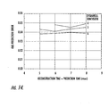
- Figure 12 shows the effect of embedding time delay on prediction accuracy for a 5-dimensional space predicting ahead 8 msec.
- the Y-axis is the relative prediction error, the RMS error divided by standard deviation of the predicted signal.
- a delay of 6 msec proved to be optimal, although any value between roughly 5 and 8 msec provides nearly as good accuracy.
- control update rate In practical terms, the control update rate, embedding delay, and prediction time would normally be linked.
- the control system would be expected to accept data at some rate (say every 3 msec), build the embedded state space location from every second value, perform a state space prediction, calculate the corresponding actuator settings, and output the result.
- the prediction time would probably be some multiple of the system sampling time.
- Figure 13 shows the effect of embedding delay and prediction time, when prediction time is constrained to be an integer multiple of embedding delay using 5-dimensional state spaces. In principle, optimal accuracy with a prediction time of 6 msec could be obtained with 1, 2, 3, or 6 msec embedding delays, but the longest embedding delay always provided the optimal prediction accuracy.
- the minimum prediction error was again obtained with a prediction time equal to embedding delay of 6 msec. Still, any of these prediction times would provide acceptable control accuracy, so limitations of the calculation rate of the real-time test bed computer could be addressed by adjusting the embedding delay and prediction time.
- the combination selected for the demonstration should be made based on a combination of maximizing predictive accuracy subject to the capabilities of the control computer.
- the real-time demonstration we used a 6-D space and an embedding delay of 6 msec. It turns out that we could have used a shorter embedding delay without problems.
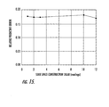
- the next measure of state space size is the period of time covered by the data used to build the space. Using a dimension of 5, and embedding delay and prediction time of 6 msec, we obtained the results shown in Figure 16. This result is fairly impressive: improving accuracy beyond some level requires a large increase in the state space size, which probably is not worthwhile.
- a state space built of 1 sec of vibration data does nearly as well as a state space built of 10 sec of data.
- the first method is to fit several recent values produced by the state space to a 20-Hz sine wave, and use the resulting sine wave to generate the output to the actuators.
- a simple analysis routine performs a least-squares fit of several values to a 20-Hz sine wave. As long as the number of points used to perform the fit covered at least 1 ⁇ 2 of a period, essentially uniform accuracy is obtained. The computation time associated with this analysis step is modest, and the prediction accuracy is actually improved (because the non-20-Hz components of the prediction are removed). This "filter” suppresses non-20-Hz behaviors by greater than 20 dB.
- the least-squares filter introduces a delay to updates of the 20-Hz signal, in this case of roughly 1 ⁇ 2 period (25 msec). Consequently, for maximum vibration control accuracy, the predictor should predict the 20-Hz behavior 1 ⁇ 2 period ahead, in addition to any other prediction times required for analysis and transport.
- the least-squares filter suppresses spurious non-20-Hz behaviors fairly effectively, it does not guarantee that the actuator output signals are identically 20-Hz.
- the proxy gearbox correction is not stable, the least squares filter will permit other frequencies (at least in the range of 12-30 Hz) to survive to the actuator outputs.
- stability of the proxy gearbox should not prove to be a problem in a flight version of the system, there is a risk that an unforeseen instability could affect the control authority of the controller, which could prove unacceptable for flight certification. Consequently, it seems prudent to pursue a different approach in the long run.
- the main alternative approach is to use the state space to predict the amplitude of the 20-Hz component of the vibration, rather than the instantaneous value of the 20-Hz component. This amplitude is then used to drive 20-Hz oscillators for each actuator, ensuring that the actuator outputs are identically at 20 Hz. Interestingly enough, using the state space to predict amplitude actually improves prediction accuracy modestly: without smoothing the predictions, the relative prediction errors were only 12.7%, compared to previous errors of 17-20%. Suitably smoothing the result (e.g., a trended moving average) would be expected to improve the overall prediction accuracy.
- the other major function of the front-office process is to apply the control model 120, Fig. 2 to produce the actuator outputs.
- the coefficients of [ A ] should vary with the amplitude of both the cosine and sine components of G r , since the airframe response is somewhat nonlinear. It is likely that simply accounting for the amplitude of G r would be sufficient to correct for this nonlinearity (although we did not specifically investigate this in testing). Still, the control accuracy achieved with a fixed [ A ] matrix was good enough that the added complexity of using a variable matrix does not seem warranted. Consequently, the demonstration system used a fixed control matrix, which would be provided by the back office process in a fully operational control system. The process of estimating and updating the control matrix would be performed by back office 110, Fig. 2.
- Back office process 110 is not involved in instant-by-instant vibration control, but instead makes, checks, and updates the settings required by the front office process. In a sense, it is more "contemplative" than the front office process, in that it can afford to examine phenomena over a period of time to optimize the results.
- the basic tasks of the back office process include the following: generating the proxy gearbox correction matrix, generating and update the actuator control matrix, generating and modifying the state space prediction model, and performing system diagnostics.
- the existing prior art ACSR system performs at least one of these functions already, generating and modifying the actuator control matrix.
- the system of this invention also determines to what extent the current source of control error is a function of errors in the control matrix or the state space predictor, and then take appropriate corrective action.
- the current ACSR system performs a simple test prior to flight, in which each actuator is driven in sequence with a 20-Hz sine wave to determine the impact on the airframe-mounted accelerometers.
- the resulting actuator response matrix is then used to calculate the first estimate for the control matrix.
- the system of this invention could perform this test as well, at the same time determining the influence of each actuator on the gearbox accelerometer, generating the proxy gearbox correction matrix.
- the actuator response matrix and proxy correction matrix hardly change over time, so there is no reason that these matrices could not be carried over from one flight to the next. In fact, it seems reasonable to compare the current and past values of these matrices as a check on the condition of the control system.
- the proxy correction matrix does not need to be updated during control system operation, since there is no reason to believe that it should vary significantly.
- the control matrix can accommodate errors in the proxy gearbox correction model. This is fortunate, since it could prove to be difficult to differentiate between errors in the proxy gearbox correction model and the control model.
- the current ACSR system continually checks the response of the airframe accelerometers to update the control matrix and schedule the actuator demand signals for the next rotor rotation.
- This task is relatively simple, because the assumption is made that the rotor input is constant.
- the rotor input is not constant, and the control model is more nearly static as flight conditions change.
- the proportionality between the proxy gearbox vibration and actuator inputs ensures that large changes in the control model will not be needed, so updating the control model will occur more occasionally and with smaller incremental changes than with the current ACSR system.
- the process of updating the control model involves comparing the actual 20-Hz component of the proxy gearbox vibration and actual actuator inputs with the anticipated response of the accelerometers, and correcting the control matrix to minimize the overall cost function. Since a very similar version of this process is already implemented in the existing ACSR system (and performed at an update rate far higher than would be needed in our nonlinearly enhanced version), there is no question about the feasibility of performing this process in a flight version of the control system.
- the other major control-related function of the back office process 202, Fig. 2 is to generate and update the state space model that maps the proxy gearbox vibration to its 20-Hz component.
- the process of checking the suitability of the current state space includes back office process 202 monitoring the proxy gearbox vibration used in the front office process and compare the state space prediction with the actual 20-Hz vibration component of the data.
- the state space model does this in real time, probably with some level of prediction involved.
- the back office process can calculate the 20-Hz component using a digital filter. When a significant level of error is detected in the current state space model, the back office process could inject a new state space model for the front office process to use.
- the final function of the back office process is to monitor the operating condition of the control system itself. This would involve monitoring the status of each of the accelerometers, which have diagnostic circuits built in, and similarly comparing the actuator demand signals with the actuator feedback signals to the servo amplifiers. If problems arise, the back office process could log them for attention during aircraft maintenance. Beyond this, there is an opportunity to use the back office process to monitor the dynamic performance of the control system. For example, the proxy gearbox correction model, control model, and state space models all could be carried forward from one flight to another. If there is significant variation in any of the models, this could signal a change in the rotor condition or the structural condition of the airframe.
- the real-time demonstration system was developed using Simulink, a Matlab add-on, using a notebook computer belonging to Westland.
- the resulting control system algorithm was then downloaded to Westland's DSPace controller.
- the DSPace controller is a computer plug-in card that uses a Texas Instruments TMS320C40 DSP processor to control operations related to obtaining input from data acquisition channels, producing output to control channels, and perform data processing in real time. It is mounted in an Autobox backplane computer, which is connected by ethemet cable to the Simulink development computer.
- the system is quite capable, as it easily hosts an implementation of Westland's existing ACSR algorithm.
- the principal technical hurdle involved in implementing the nonlinearly enhanced controller on the real-time test bed proved to be making state space predictor 102 work in the context of the combined Simulink/DSPace compiler.
- the basic state space predictor code, written in C had been successfully made to work as stand-alone Windows programs, a DLL that could be called from any Windows programming language, and a MEX file, a special DLL that can be called from Matlab.
- the code had to be modified further to work as an S-function, a special DLL format for use with Simulink.
- the state space predictor makes predictions using polynomial fits of several nearest neighbors to the point of interest.
- the order of the polynomial that is used can be set as desired by the user.
- a first-order fit i.e., a linear model of the neighborhood, as this provides very good prediction accuracy with a modest computational burden, but quadratic or cubic models can be used if a state space has very complicated behavior.
- Predictor 102 was only capable of a 0-th order fit. It was clear that one ultimately could debug the code so that all prediction orders would work.
- the prediction that is output is the average of the values of the several neighbors, with no correction for the location of the desired point relative to each neighbor.
- two predictions were performed using EH-101 flight vibration data to predict the blade passing frequency component of the vibration. With a first-order fit, an RMS error of 16.5% was obtained. With a 0-th order fit, an RMS error of 19.0% was obtained. Thus, using the lower-order fit increased the prediction error by 2.5 percentage points.
- Figure 18 presents a schematic diagram of the overall control configuration that resulted.
- the figure has been modified from its form as implemented on the DSPace system, partly because some of the constructions used on the DSPace system are not supported in ordinary Simulink and partly for improved clarity.
- the DSPace implementation of the model required that the inputs and outputs of the model be scaled upward and downward, respectively: inputs to the model had to be scaled up to minimize round-off error, and the outputs scaled down to avoid saturating the analog outputs. This led to some confusion and bookkeeping errors in debugging the system, but the diagram is functionally correct.
- the overall cycle time for this control system was chosen to be 3 msec, one-half the time delay used for the state space embedding in the predictor.
- the overall cycle time for this control system was chosen to be 3 msec, one-half the time delay used for the state space embedding in the predictor.
- there were 16.67 control cycles in each 20-Hz blade passing allowing for a reasonable representation of a 20-Hz sine wave without a dual-clock control algorithm.
- the system could have achieved a cycle time of 1 msec, indicating that the test bed has substantial computational power beyond that required.
- Implementing the control on a shorter cycle would have increased the bookkeeping required to account for the different analysis cycle times of the predictor and the rest of the control system, so we used the longer cycle time for simplicity.
- the raw gearbox vibration signal, G enters the system via Inputl 400.
- this signal did not have to be low-pass filtered to kill the high-frequency gearbox vibrations as it would in a flight version of the system.
- the accelerometer amplifiers used in the ACSR test rig provide 200-Hz anti-alias filtering, which serves a similar purpose but is less aggressive than would ultimately be used.
- Sum block 402 subtracts the estimated effect of the actuators on the gearbox response (G p ), producing an estimate of the proxy gearbox vibration, G r '.
- This signal then moves to Predict/Filter block 404, where six sequential G r ' . values are time delay embedded and used to predict the 20-Hz component of G r ', G r20 . Sixteen sequential values of G r20 , covering almost a period of the vibration, are used to perform a least-squares estimate of the cosine and sine components of G r20 , eliminating spurious frequencies.
- the cosine and sine components of the 20-Hz proxy vibration then pass to the Apply Control block 406.
- the 20-Hz components are first multiplied by the control matrix to produce the cosine and sine components of the actuator demand signals.
- a copy of the actuator demand signals is then multiplied by the proxy gearbox correction matrix to produce the corresponding proxy gearbox corrections.
- These results then go to respective blocks 408 and 410 where the cosine and sine components are turned into actual time signals.
- the actuator demand signals are then sent to the analog output ports that drive the actuator servo amplifiers, while the proxy correction signals are fed back to the Proxy Gearbox Correction sum.
- the control and proxy gearbox correction matrices were calculated based on previous tests, analogous to being fed from the back office process.
- the first of these tests is an open-loop test, in which each actuator is driven individually to determine its influence on the accelerometers, including the gearbox accelerometer. This information is used to calculate the proxy gearbox correction matrix and a first estimate for the control matrix.
- the second test is a closed-loop test, in which the existing ACSR algorithm is used to optimize the control matrix during control. Since the existing ACSR system does not work well with non-periodic signals, the closed loop test was run with a 20-Hz sine wave driving the head shaker. By the same token, the existing ACSR algorithm could be modified to find the optimal control averaged over time, so there is no doubt that the back office process could find the optimal control matrix.
Landscapes
- Physics & Mathematics (AREA)
- General Physics & Mathematics (AREA)
- Engineering & Computer Science (AREA)
- Automation & Control Theory (AREA)
- Vibration Prevention Devices (AREA)
- Measuring Volume Flow (AREA)
Applications Claiming Priority (2)
| Application Number | Priority Date | Filing Date | Title |
|---|---|---|---|
| US10/244,583 US7017857B2 (en) | 2002-09-16 | 2002-09-16 | Active vibration control system |
| US244583 | 2002-09-16 |
Publications (3)
| Publication Number | Publication Date |
|---|---|
| EP1400885A2 true EP1400885A2 (de) | 2004-03-24 |
| EP1400885A3 EP1400885A3 (de) | 2005-01-12 |
| EP1400885B1 EP1400885B1 (de) | 2012-10-24 |
Family
ID=31946394
Family Applications (1)
| Application Number | Title | Priority Date | Filing Date |
|---|---|---|---|
| EP03255684A Expired - Lifetime EP1400885B1 (de) | 2002-09-16 | 2003-09-11 | Aktive Schwingungssteuervorrichtung |
Country Status (2)
| Country | Link |
|---|---|
| US (1) | US7017857B2 (de) |
| EP (1) | EP1400885B1 (de) |
Cited By (3)
| Publication number | Priority date | Publication date | Assignee | Title |
|---|---|---|---|---|
| WO2014113619A1 (en) * | 2013-01-18 | 2014-07-24 | Lord Corporation | Systems and methods for implementing directional force weighting with circular force generators |
| EP3201076A4 (de) * | 2014-10-01 | 2018-05-23 | Sikorsky Aircraft Corporation | Aktive schwingungskontrolle eines drehflüglers |
| WO2021001734A1 (fr) * | 2019-07-03 | 2021-01-07 | Etat Français Représenté Par Le Délégué Général De L'armement | Dispositif de détection de l'approche d'un état d'anneaux tourbillonnaires, aérodyne à voilure tournante le comprenant, et procédé associé |
Families Citing this family (37)
| Publication number | Priority date | Publication date | Assignee | Title |
|---|---|---|---|---|
| FR2864025B1 (fr) * | 2003-12-23 | 2007-01-12 | Eurocopter France | Procede et dispositif pour reduire par un empennage orientable les vibrations engendrees sur le fuselage d'un helicoptere |
| FR2864026B1 (fr) * | 2003-12-23 | 2007-01-19 | Eurocopter France | Procede et dispositif pour reduire par une derive orientable les vibrations engendrees sur le fuselage d'un helicoptere |
| US8090482B2 (en) * | 2007-10-25 | 2012-01-03 | Lord Corporation | Distributed active vibration control systems and rotary wing aircraft with suppressed vibrations |
| US8162606B2 (en) | 2004-08-30 | 2012-04-24 | Lord Corporation | Helicopter hub mounted vibration control and circular force generation systems for canceling vibrations |
| US7722322B2 (en) * | 2004-08-30 | 2010-05-25 | Lord Corporation | Computer system and program product for controlling vibrations |
| US8435002B2 (en) * | 2004-08-30 | 2013-05-07 | Lord Corporation | Helicopter vibration control system and rotating assembly rotary forces generators for canceling vibrations |
| US8267652B2 (en) | 2004-08-30 | 2012-09-18 | Lord Corporation | Helicopter hub mounted vibration control and circular force generation systems for canceling vibrations |
| US7448854B2 (en) * | 2004-08-30 | 2008-11-11 | Lord Corporation | Helicopter vibration control system and rotary force generator for canceling vibrations |
| EP2339206B1 (de) * | 2006-06-01 | 2016-03-30 | LORD Corporation | System zur Steuerung der Maschinenschwingung |
| US7648338B1 (en) * | 2006-09-14 | 2010-01-19 | Sikorsky Aircraft Corporation | Dual higher harmonic control (HHC) for a counter-rotating, coaxial rotor system |
| US7486469B1 (en) * | 2007-10-31 | 2009-02-03 | Hitachi Global Storage Technologies Netherlands B.V. | Minimizing a mechanical mode excitation utilizing a generated seek trajectory |
| EP2241502B1 (de) * | 2009-04-13 | 2017-03-08 | Sikorsky Aircraft Corporation | Aktive Schwingungsunterdrückung durch Leistungsminimierung |
| JP5177157B2 (ja) * | 2010-03-17 | 2013-04-03 | カシオ計算機株式会社 | 波形発生装置および波形発生プログラム |
| FR2967508B1 (fr) * | 2010-11-16 | 2014-02-21 | Ixmotion | Procede et dispositif de controle actif de vibrations mecaniques par mise en oeuvre d'une loi de controle constituee d'un correcteur central et d'un parametre de youla |
| KR101752645B1 (ko) | 2011-02-04 | 2017-06-30 | 로오드 코포레이션 | 공진 관성형 액추에이터를 구비한 회전익 항공기 진동 제어 시스템 |
| US20120292434A1 (en) * | 2011-04-29 | 2012-11-22 | Sikorsky Aircraft Corporation | Six Degrees Of Freedom Vibration Suppression |
| GB2492965B (en) * | 2011-07-15 | 2018-05-02 | Agustawestland Ltd | A system and method for reducing the transmission of vibration from a first vibrating body to a second body |
| US9376807B2 (en) | 2011-08-23 | 2016-06-28 | Teledyne Scientific & Imaging, Llc | Passive structures with high stiffness and high damping properties |
| EP2729927A4 (de) * | 2011-10-06 | 2014-07-30 | Cae Inc | Verfahren zur entwicklung eines mathematischen modells einer fahrzeugdynamik zur verwendung in einem rechnergesteuerten fahrzeugsimulator |
| US20150097074A1 (en) * | 2013-10-03 | 2015-04-09 | Sikorsky Aircraft Corporation | Dual-frequency active vibration control |
| US9284048B2 (en) * | 2013-10-14 | 2016-03-15 | Sikorsky Aircraft Corporation | Global airframe health characterization |
| WO2015089404A2 (en) * | 2013-12-13 | 2015-06-18 | Lord Corporation | Redundant active vibration and noise control systems and methods |
| US10466266B2 (en) * | 2014-08-14 | 2019-11-05 | University Of North Dakota | Flight parameter prediction using neural networks |
| WO2016048442A1 (en) * | 2014-09-26 | 2016-03-31 | Sikorsky Aircraft Corporation | Damage adaptive vibration control |
| EP3201077B1 (de) | 2014-10-01 | 2020-05-20 | Sikorsky Aircraft Corporation | Doppelrotor, drehflügelflugzeug |
| WO2016111733A1 (en) * | 2014-12-16 | 2016-07-14 | Sikorsky Aircraft Corporation | Variable amplitude force generator |
| DE102016218031B4 (de) * | 2016-09-20 | 2020-09-03 | Zf Friedrichshafen Ag | Verfahren zur Prädiktion von Vibrationen eines Luftfahrzeugs |
| WO2018067028A1 (ru) * | 2016-10-06 | 2018-04-12 | Валерий Туркубеевич ПЧЕНТЛЕШЕВ | Винтокрылый летательный аппарат |
| FR3063972A1 (fr) * | 2017-03-20 | 2018-09-21 | Airbus Helicopters | Systemes antivibratoire equipant un giravion, giravion associe et methode de reglage d'un tel systeme antivibratoire. |
| US11126534B2 (en) * | 2017-03-31 | 2021-09-21 | Cae Inc. | Troubleshooting a model defining a dynamic behavior of a simulated interactive object |
| CN109131854A (zh) * | 2017-06-28 | 2019-01-04 | 重庆邮电大学 | 低噪声无人机及其降噪控制方法 |
| CN115867877B (zh) * | 2020-08-31 | 2026-04-10 | 阿尔卑斯阿尔派株式会社 | 输入装置 |
| CN112311526B (zh) * | 2020-10-26 | 2022-08-26 | 湘潭大学 | 基于s函数发生器的模块化多涡卷混沌电路 |
| US11940417B2 (en) * | 2021-02-02 | 2024-03-26 | Toyota Motor Engineering & Manufacturing North America, Inc. | Systems and methods for machine learning based flexural wave absorber |
| CN115081271B (zh) * | 2022-06-02 | 2024-04-05 | 西安交通大学 | 基于数字模拟器的叶端定时系统校核方法及校核系统 |
| CN116540550B (zh) * | 2023-06-16 | 2025-10-03 | 上海交通大学 | 直升机多谐波多通道全局振动主动控制方法 |
| CN117970864B (zh) * | 2024-04-02 | 2024-05-31 | 万科思自动化(上海)有限公司 | 基于电信号分析的石油天然气plc控制监测系统及方法 |
Citations (1)
| Publication number | Priority date | Publication date | Assignee | Title |
|---|---|---|---|---|
| US5853144A (en) | 1995-11-18 | 1998-12-29 | Gkn Westland Helicopters Limited | Helicopter and method for reducing vibration of a helicopter fuselage |
Family Cites Families (13)
| Publication number | Priority date | Publication date | Assignee | Title |
|---|---|---|---|---|
| US4819182A (en) * | 1985-06-21 | 1989-04-04 | Westland Plc | Method and apparatus for reducing vibration of a helicopter fuselage |
| JP2879946B2 (ja) * | 1990-06-04 | 1999-04-05 | 帝人製機株式会社 | 航空機翼のフラッタ抑制システム |
| FR2678578B1 (fr) * | 1991-07-02 | 1993-10-22 | Aerospatiale Ste Nationale Indle | Procede et dispositif pour la reduction des oscillations a caractere divergent du fuselage d'un helicoptere. |
| FR2680848B1 (fr) * | 1991-08-29 | 1995-03-17 | Aerospatiale Ste Nat Indle | Procede et dispositif pour filtrer les excitations vibratoires transmises entre deux pieces, notamment entre le rotor et le fuselage d'un helicoptere. |
| GB9123304D0 (en) * | 1991-11-02 | 1992-09-23 | Westland Helicopters | Integrated vibration reducing and health monitoring systems |
| JP3265670B2 (ja) * | 1993-01-21 | 2002-03-11 | 株式会社ニコン | ステージ装置、ステージ駆動方法、及び露光装置 |
| FR2731405B1 (fr) * | 1995-03-10 | 1997-05-09 | Eurocopter France | Systeme pour minimiser l'excitation dynamique d'un helicoptere |
| US5734246A (en) * | 1995-05-16 | 1998-03-31 | The Aerospace Corporation | Active piezo-electric vibration isolation and directional systems |
| US5880362A (en) * | 1995-09-06 | 1999-03-09 | Engineering Technology Associates, Inc. | Method and system for simulating vehicle and roadway interaction |
| US5973441A (en) * | 1996-05-15 | 1999-10-26 | American Research Corporation Of Virginia | Piezoceramic vibrotactile transducer based on pre-compressed arch |
| US6053269A (en) * | 1998-08-13 | 2000-04-25 | The Board Of Regents Of The University Of Oklahoma | Vehicle/bridge vibration mitigation assembly |
| US6865466B2 (en) | 2000-04-27 | 2005-03-08 | American Axle & Manufacturing, Inc. | Active vibration cancellation of gear mesh vibration |
| US6402089B1 (en) * | 2001-03-02 | 2002-06-11 | General Dynamics Advanced Technology Services, Inc. | System for control of active system for vibration and noise reduction |
-
2002
- 2002-09-16 US US10/244,583 patent/US7017857B2/en not_active Expired - Fee Related
-
2003
- 2003-09-11 EP EP03255684A patent/EP1400885B1/de not_active Expired - Lifetime
Patent Citations (1)
| Publication number | Priority date | Publication date | Assignee | Title |
|---|---|---|---|---|
| US5853144A (en) | 1995-11-18 | 1998-12-29 | Gkn Westland Helicopters Limited | Helicopter and method for reducing vibration of a helicopter fuselage |
Non-Patent Citations (6)
| Title |
|---|
| "Systems & controls letter", vol. 31, 1997, article ABARBANEL,H.D.I., KORZINOV, L., MEES, A.I. AND STAROBINETS ,I.M.: "Optimal control of Nonlinear Systems to given Orbits", pages: 263 - 276 |
| Abarbanel, H.D.I, Analysis of Observed Chaotic Data, Springer_ Verlag, 1996 |
| ABARBANEL, H.D.I., BROWN, R., J.J. AND TSIMRING, L.S.: "The Analysis of observed Chaotic Data in Physical Systems,", REVIEWS OF MODERN PHYSICS, no. 4, - October 1993 (1993-10-01), pages 1331 - 1392, XP000937897, DOI: doi:10.1103/RevModPhys.65.1331 |
| FREIDMAN, J.H.; BENTLEY, J.L.; AND FINKLE, R.A.: "an Algorithm for finding Best Matches in logarithimic Expected Time", ACM TRANSACTIONS ON MATHEMATICAL SOFTWARE, no. 3, - September 1977 (1977-09-01), pages 209 - 226, XP008089525, DOI: doi:10.1145/355744.355745 |
| RHODES,C., MORARI, M., TSIMRING,L.S., AND RULKOV, N.F.: "Data-Based control Trajectory Planning for Nonlinear Systems", PHYSICAL REVIEW E, no. 3, - September 1997 (1997-09-01), pages 2398 - 2406 |
| RULKOV, N.F., TSIMRING,L.S., AND ABARBANEL, H.D.I.,: "Tracking Unstable Obits in Chaos Using dissipative Feedback control", PHYSICAL REVIEW E, no. 1, - July 1994 (1994-07-01), pages 314 - 324 |
Cited By (9)
| Publication number | Priority date | Publication date | Assignee | Title |
|---|---|---|---|---|
| WO2014113619A1 (en) * | 2013-01-18 | 2014-07-24 | Lord Corporation | Systems and methods for implementing directional force weighting with circular force generators |
| US10293925B2 (en) | 2013-01-18 | 2019-05-21 | Lord Corporation | Systems and methods for implementing directional force weighting with circular force generators |
| EP3201076A4 (de) * | 2014-10-01 | 2018-05-23 | Sikorsky Aircraft Corporation | Aktive schwingungskontrolle eines drehflüglers |
| US10167079B2 (en) | 2014-10-01 | 2019-01-01 | Sikorsky Aircraft Corporation | Main rotor rotational speed control for rotorcraft |
| US10443675B2 (en) | 2014-10-01 | 2019-10-15 | Sikorsky Aircraft Corporation | Active vibration control of a rotorcraft |
| US10717521B2 (en) | 2014-10-01 | 2020-07-21 | Sikorsky Aircraft Corporation | Hub separation in dual rotor rotary wing aircraft |
| WO2021001734A1 (fr) * | 2019-07-03 | 2021-01-07 | Etat Français Représenté Par Le Délégué Général De L'armement | Dispositif de détection de l'approche d'un état d'anneaux tourbillonnaires, aérodyne à voilure tournante le comprenant, et procédé associé |
| FR3098297A1 (fr) * | 2019-07-03 | 2021-01-08 | Etat français représenté par le délégué général de l’armement | Dispositif de detection de l'approche d'un etat d'anneaux tourbillonaires, aerodyne a voilure tournante le comprenant, et procede associe |
| US11801933B2 (en) | 2019-07-03 | 2023-10-31 | Etat Français Représenté Par Le Délégué Général De L'armement | Device for detecting the approach of a vortex ring state, rotary-wing aerodyne comprising said device, and associated method |
Also Published As
| Publication number | Publication date |
|---|---|
| US7017857B2 (en) | 2006-03-28 |
| US20040050999A1 (en) | 2004-03-18 |
| EP1400885A3 (de) | 2005-01-12 |
| EP1400885B1 (de) | 2012-10-24 |
Similar Documents
| Publication | Publication Date | Title |
|---|---|---|
| US7017857B2 (en) | Active vibration control system | |
| Longman | Iterative learning control and repetitive control for engineering practice | |
| Mitchell et al. | Advanced continuous simulation language (ACSL) | |
| CN119937330B (zh) | 多轴伺服系统的同步控制方法、装置及设备 | |
| EP3379349A1 (de) | Steuerungsvorrichtung, steuerungsprogramm und steuerungssystem | |
| EP3584722B1 (de) | Verfahren und systeme zur steuerung von maschinenvibrationen | |
| WO2020162199A1 (ja) | 制御装置、モデル作成方法および制御プログラム | |
| Mollov et al. | μ-synthesis and hardware-in-the-loop simulation of miniature helicopter control system | |
| JP7331779B2 (ja) | 機械制御システム、波形生成装置、波形生成方法、および波形生成プログラム | |
| Kvaternik | Exploratory studies in generalized predictive control for active aeroelastic control of tiltrotor aircraft | |
| McEver | Optimal vibration suppression using on-line pole/zero identification | |
| Aponso et al. | Identification of higher order helicopter dynamics using linear modeling methods | |
| Shere et al. | A methodology for design, test, and evaluation of real-time systems | |
| Svalstedt | Modeling and Simulation of a Remote Controlled Weapon Station | |
| Tokhi et al. | A SIMULINK environment for simulation and control of flexible manipulator systems | |
| Chaber et al. | Automatic code generation of MIMO model predictive control algorithms using transcompiler | |
| Tomlinson et al. | Computer-Aided control law research–from concept to flight test | |
| Soares et al. | Modeling and control of multibody system with flexible appendages | |
| Sushchenko | Robust Control of Inertially Stabilized Platforms for Ground Vehicles on the Basis of Synthesis | |
| Hägglund | Implementation of a latency controller in an 8-DOF driving simulator. A Latency controller based on the Otto-Smith predictor, with a model developed using System Identification. | |
| Schubert | Active Vibration Control by Means of Concurrent Implementation Techniques | |
| Chang | Shaping inputs to reduce vibration in flexible space structures | |
| Yu et al. | Advanced flexible pointing testbed and control system design | |
| Schmid et al. | Computer-Aided Design of Spacecraft Control Systems | |
| CN118534753A (zh) | 信息处理装置、信息处理方法以及记录介质 |
Legal Events
| Date | Code | Title | Description |
|---|---|---|---|
| PUAI | Public reference made under article 153(3) epc to a published international application that has entered the european phase |
Free format text: ORIGINAL CODE: 0009012 |
|
| AK | Designated contracting states |
Kind code of ref document: A2 Designated state(s): AT BE BG CH CY CZ DE DK EE ES FI FR GB GR HU IE IT LI LU MC NL PT RO SE SI SK TR |
|
| AX | Request for extension of the european patent |
Extension state: AL LT LV MK |
|
| 17P | Request for examination filed |
Effective date: 20040322 |
|
| PUAL | Search report despatched |
Free format text: ORIGINAL CODE: 0009013 |
|
| AK | Designated contracting states |
Kind code of ref document: A3 Designated state(s): AT BE BG CH CY CZ DE DK EE ES FI FR GB GR HU IE IT LI LU MC NL PT RO SE SI SK TR |
|
| AX | Request for extension of the european patent |
Extension state: AL LT LV MK |
|
| RIC1 | Information provided on ipc code assigned before grant |
Ipc: 7G 10K 11/178 B Ipc: 7G 05D 19/02 A Ipc: 7B 64C 27/00 B |
|
| AKX | Designation fees paid |
Designated state(s): AT BE BG CH CY CZ DE DK EE ES FI FR GB GR HU IE IT LI LU MC NL PT RO SE SI SK TR |
|
| GRAP | Despatch of communication of intention to grant a patent |
Free format text: ORIGINAL CODE: EPIDOSNIGR1 |
|
| GRAS | Grant fee paid |
Free format text: ORIGINAL CODE: EPIDOSNIGR3 |
|
| GRAA | (expected) grant |
Free format text: ORIGINAL CODE: 0009210 |
|
| AK | Designated contracting states |
Kind code of ref document: B1 Designated state(s): AT BE BG CH CY CZ DE DK EE ES FI FR GB GR HU IE IT LI LU MC NL PT RO SE SI SK TR |
|
| REG | Reference to a national code |
Ref country code: GB Ref legal event code: FG4D |
|
| REG | Reference to a national code |
Ref country code: CH Ref legal event code: EP |
|
| REG | Reference to a national code |
Ref country code: AT Ref legal event code: REF Ref document number: 581243 Country of ref document: AT Kind code of ref document: T Effective date: 20121115 |
|
| REG | Reference to a national code |
Ref country code: IE Ref legal event code: FG4D |
|
| REG | Reference to a national code |
Ref country code: DE Ref legal event code: R096 Ref document number: 60342414 Country of ref document: DE Effective date: 20121220 |
|
| REG | Reference to a national code |
Ref country code: AT Ref legal event code: MK05 Ref document number: 581243 Country of ref document: AT Kind code of ref document: T Effective date: 20121024 |
|
| REG | Reference to a national code |
Ref country code: NL Ref legal event code: VDEP Effective date: 20121024 |
|
| PG25 | Lapsed in a contracting state [announced via postgrant information from national office to epo] |
Ref country code: FI Free format text: LAPSE BECAUSE OF FAILURE TO SUBMIT A TRANSLATION OF THE DESCRIPTION OR TO PAY THE FEE WITHIN THE PRESCRIBED TIME-LIMIT Effective date: 20121024 Ref country code: NL Free format text: LAPSE BECAUSE OF FAILURE TO SUBMIT A TRANSLATION OF THE DESCRIPTION OR TO PAY THE FEE WITHIN THE PRESCRIBED TIME-LIMIT Effective date: 20121024 Ref country code: SE Free format text: LAPSE BECAUSE OF FAILURE TO SUBMIT A TRANSLATION OF THE DESCRIPTION OR TO PAY THE FEE WITHIN THE PRESCRIBED TIME-LIMIT Effective date: 20121024 |
|
| PG25 | Lapsed in a contracting state [announced via postgrant information from national office to epo] |
Ref country code: CY Free format text: LAPSE BECAUSE OF FAILURE TO SUBMIT A TRANSLATION OF THE DESCRIPTION OR TO PAY THE FEE WITHIN THE PRESCRIBED TIME-LIMIT Effective date: 20121024 Ref country code: SI Free format text: LAPSE BECAUSE OF FAILURE TO SUBMIT A TRANSLATION OF THE DESCRIPTION OR TO PAY THE FEE WITHIN THE PRESCRIBED TIME-LIMIT Effective date: 20121024 Ref country code: GR Free format text: LAPSE BECAUSE OF FAILURE TO SUBMIT A TRANSLATION OF THE DESCRIPTION OR TO PAY THE FEE WITHIN THE PRESCRIBED TIME-LIMIT Effective date: 20130125 Ref country code: PT Free format text: LAPSE BECAUSE OF FAILURE TO SUBMIT A TRANSLATION OF THE DESCRIPTION OR TO PAY THE FEE WITHIN THE PRESCRIBED TIME-LIMIT Effective date: 20130225 Ref country code: BE Free format text: LAPSE BECAUSE OF FAILURE TO SUBMIT A TRANSLATION OF THE DESCRIPTION OR TO PAY THE FEE WITHIN THE PRESCRIBED TIME-LIMIT Effective date: 20121024 |
|
| PG25 | Lapsed in a contracting state [announced via postgrant information from national office to epo] |
Ref country code: AT Free format text: LAPSE BECAUSE OF FAILURE TO SUBMIT A TRANSLATION OF THE DESCRIPTION OR TO PAY THE FEE WITHIN THE PRESCRIBED TIME-LIMIT Effective date: 20121024 |
|
| PG25 | Lapsed in a contracting state [announced via postgrant information from national office to epo] |
Ref country code: CZ Free format text: LAPSE BECAUSE OF FAILURE TO SUBMIT A TRANSLATION OF THE DESCRIPTION OR TO PAY THE FEE WITHIN THE PRESCRIBED TIME-LIMIT Effective date: 20121024 Ref country code: DK Free format text: LAPSE BECAUSE OF FAILURE TO SUBMIT A TRANSLATION OF THE DESCRIPTION OR TO PAY THE FEE WITHIN THE PRESCRIBED TIME-LIMIT Effective date: 20121024 Ref country code: SK Free format text: LAPSE BECAUSE OF FAILURE TO SUBMIT A TRANSLATION OF THE DESCRIPTION OR TO PAY THE FEE WITHIN THE PRESCRIBED TIME-LIMIT Effective date: 20121024 Ref country code: EE Free format text: LAPSE BECAUSE OF FAILURE TO SUBMIT A TRANSLATION OF THE DESCRIPTION OR TO PAY THE FEE WITHIN THE PRESCRIBED TIME-LIMIT Effective date: 20121024 Ref country code: BG Free format text: LAPSE BECAUSE OF FAILURE TO SUBMIT A TRANSLATION OF THE DESCRIPTION OR TO PAY THE FEE WITHIN THE PRESCRIBED TIME-LIMIT Effective date: 20130124 |
|
| PG25 | Lapsed in a contracting state [announced via postgrant information from national office to epo] |
Ref country code: RO Free format text: LAPSE BECAUSE OF FAILURE TO SUBMIT A TRANSLATION OF THE DESCRIPTION OR TO PAY THE FEE WITHIN THE PRESCRIBED TIME-LIMIT Effective date: 20121024 Ref country code: IT Free format text: LAPSE BECAUSE OF FAILURE TO SUBMIT A TRANSLATION OF THE DESCRIPTION OR TO PAY THE FEE WITHIN THE PRESCRIBED TIME-LIMIT Effective date: 20121024 |
|
| PLBE | No opposition filed within time limit |
Free format text: ORIGINAL CODE: 0009261 |
|
| STAA | Information on the status of an ep patent application or granted ep patent |
Free format text: STATUS: NO OPPOSITION FILED WITHIN TIME LIMIT |
|
| 26N | No opposition filed |
Effective date: 20130725 |
|
| PG25 | Lapsed in a contracting state [announced via postgrant information from national office to epo] |
Ref country code: ES Free format text: LAPSE BECAUSE OF FAILURE TO SUBMIT A TRANSLATION OF THE DESCRIPTION OR TO PAY THE FEE WITHIN THE PRESCRIBED TIME-LIMIT Effective date: 20130204 |
|
| REG | Reference to a national code |
Ref country code: DE Ref legal event code: R097 Ref document number: 60342414 Country of ref document: DE Effective date: 20130725 |
|
| PG25 | Lapsed in a contracting state [announced via postgrant information from national office to epo] |
Ref country code: MC Free format text: LAPSE BECAUSE OF FAILURE TO SUBMIT A TRANSLATION OF THE DESCRIPTION OR TO PAY THE FEE WITHIN THE PRESCRIBED TIME-LIMIT Effective date: 20121024 |
|
| REG | Reference to a national code |
Ref country code: CH Ref legal event code: PL |
|
| GBPC | Gb: european patent ceased through non-payment of renewal fee |
Effective date: 20130911 |
|
| REG | Reference to a national code |
Ref country code: DE Ref legal event code: R119 Ref document number: 60342414 Country of ref document: DE Effective date: 20140401 |
|
| REG | Reference to a national code |
Ref country code: FR Ref legal event code: ST Effective date: 20140530 |
|
| REG | Reference to a national code |
Ref country code: IE Ref legal event code: MM4A |
|
| PG25 | Lapsed in a contracting state [announced via postgrant information from national office to epo] |
Ref country code: LI Free format text: LAPSE BECAUSE OF NON-PAYMENT OF DUE FEES Effective date: 20130930 Ref country code: GB Free format text: LAPSE BECAUSE OF NON-PAYMENT OF DUE FEES Effective date: 20130911 Ref country code: IE Free format text: LAPSE BECAUSE OF NON-PAYMENT OF DUE FEES Effective date: 20130911 Ref country code: CH Free format text: LAPSE BECAUSE OF NON-PAYMENT OF DUE FEES Effective date: 20130930 |
|
| PG25 | Lapsed in a contracting state [announced via postgrant information from national office to epo] |
Ref country code: FR Free format text: LAPSE BECAUSE OF NON-PAYMENT OF DUE FEES Effective date: 20130930 Ref country code: DE Free format text: LAPSE BECAUSE OF NON-PAYMENT OF DUE FEES Effective date: 20140401 |
|
| PG25 | Lapsed in a contracting state [announced via postgrant information from national office to epo] |
Ref country code: TR Free format text: LAPSE BECAUSE OF FAILURE TO SUBMIT A TRANSLATION OF THE DESCRIPTION OR TO PAY THE FEE WITHIN THE PRESCRIBED TIME-LIMIT Effective date: 20121024 |
|
| PG25 | Lapsed in a contracting state [announced via postgrant information from national office to epo] |
Ref country code: LU Free format text: LAPSE BECAUSE OF NON-PAYMENT OF DUE FEES Effective date: 20130911 Ref country code: HU Free format text: LAPSE BECAUSE OF FAILURE TO SUBMIT A TRANSLATION OF THE DESCRIPTION OR TO PAY THE FEE WITHIN THE PRESCRIBED TIME-LIMIT; INVALID AB INITIO Effective date: 20030911 |