EP1400914A2 - Connecteur à profil fin avec un couvercle simple à manipuler et bloqué de façon sûre à l'état fermé - Google Patents
Connecteur à profil fin avec un couvercle simple à manipuler et bloqué de façon sûre à l'état fermé Download PDFInfo
- Publication number
- EP1400914A2 EP1400914A2 EP03255742A EP03255742A EP1400914A2 EP 1400914 A2 EP1400914 A2 EP 1400914A2 EP 03255742 A EP03255742 A EP 03255742A EP 03255742 A EP03255742 A EP 03255742A EP 1400914 A2 EP1400914 A2 EP 1400914A2
- Authority
- EP
- European Patent Office
- Prior art keywords
- cover
- housing
- locking portion
- connector according
- connector
- Prior art date
- Legal status (The legal status is an assumption and is not a legal conclusion. Google has not performed a legal analysis and makes no representation as to the accuracy of the status listed.)
- Withdrawn
Links
Images



Classifications
-
- G—PHYSICS
- G06—COMPUTING OR CALCULATING; COUNTING
- G06K—GRAPHICAL DATA READING; PRESENTATION OF DATA; RECORD CARRIERS; HANDLING RECORD CARRIERS
- G06K7/00—Methods or arrangements for sensing record carriers, e.g. for reading patterns
- G06K7/0013—Methods or arrangements for sensing record carriers, e.g. for reading patterns by galvanic contacts, e.g. card connectors for ISO-7816 compliant smart cards or memory cards, e.g. SD card readers
- G06K7/0021—Methods or arrangements for sensing record carriers, e.g. for reading patterns by galvanic contacts, e.g. card connectors for ISO-7816 compliant smart cards or memory cards, e.g. SD card readers for reading/sensing record carriers having surface contacts
-
- G—PHYSICS
- G06—COMPUTING OR CALCULATING; COUNTING
- G06K—GRAPHICAL DATA READING; PRESENTATION OF DATA; RECORD CARRIERS; HANDLING RECORD CARRIERS
- G06K13/00—Conveying record carriers from one station to another, e.g. from stack to punching mechanism
- G06K13/02—Conveying record carriers from one station to another, e.g. from stack to punching mechanism the record carrier having longitudinal dimension comparable with transverse dimension, e.g. punched card
- G06K13/08—Feeding or discharging cards
- G06K13/085—Feeding or discharging cards using an arrangement for locking the inserted card
- G06K13/0862—Feeding or discharging cards using an arrangement for locking the inserted card the locking arrangement being of the rotate-slide and lock type, such as, e.g. common in mobile phones
Definitions
- the present invention relates to a connector for use in connecting a small-sized thin-profile card, such as an IC card.
- an IC card is remarkably wide spread. Even a small-sized apparatus, such as a mobile telephone, which can always be carried by a user is provided with a connector for connecting the IC card.
- the connector of the type is required to have a thin profile and to have a function of protecting the IC card.
- a connector comprising a housing fixedly holding a contact, and an openable/closable cover for pressing a mating object to be connected against the contact to establish electrical connection.
- the IC card is inserted and removed while the cover is opened. After completion of insertion or removal of the IC card, the cover is closed and a part of the cover is engaged with the housing to be locked.
- the connector disclosed in Japanese Unexamined Patent Publication No. H10-106674 has a metallic cover in order to achieve a thin profile.
- a long slot formed in the cover is engaged with a shaft portion formed on the housing.
- the connector disclosed in Japanese Unexamined Patent Publication No. 2000-260537 also has a metallic cover in order to achieve a thin profile, like the connector disclosed in Japanese Unexamined Patent Publication No. H10-106674.
- the cover may slide along the housing to be unlocked and opened if the connector is subjected to strong mechanical shock, for example, when an apparatus equipped with the connector is dropped.
- strong mechanical shock for example, when an apparatus equipped with the connector is dropped.
- the cover is unintentionally and undesiredly opened, it is highly possible to cause instantaneous interruption or permanent interruption of a signal.
- the above-mentioned problem is difficult to solve merely by weak frictional engagement between the cover and the housing. On the contrary, if the frictional engagement is strong, it is difficult to perform an operation of opening the cover.
- Japanese Unexamined Patent Publication No. H10-106674 adopts a structure in which the cover is allowed to rotate after an axis moves from its initial position to a rotatable position. In this structure, however, a thin profile can not be achieved because of protrusion of one end of the cover during rotation.
- the long slot is divided into a circular part (rotating portion) and a rectangular part (sliding portion) in the above-mentioned publication.
- the shaft portion is integrally formed with the housing made of resin susceptible to wear, the effect of such a two-part shape does not continue for a long time because of wear of the shaft portion.
- a connector for electrically connecting a mating object.
- the connector comprises a conductive contact, a housing fixedly holding the contact, a cover connected to the housing for pressing the mating object against the contact to establish electrical connection between the mating object and the contact, and a locking portion connected to the housing and the cover for keeping the cover in a connected state in which the electrical connection is established.
- the cover is held on the housing to be rotatable in a first direction and to be movable in a second direction intersecting the first direction.
- the locking portion is engaged in a direction opposite to the first direction and in the second direction. Disconnection of the mating object being carried out by rotating the cover in the first direction to disengage the locking portion and by moving the cover in the second direction, thereby allowing the mating object to be disconnected.
- the connector 10 illustrated in the figures serves to connect a so-called IC card as a small-sized thin-profile card to a small-sized apparatus, such as a mobile telephone, which can always be carried by a user.
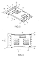
- the connector 10 comprises a housing 11 made of an insulating material, and a metallic cover 12 made of a metal and coupled to the housing 11 so as to open and close an upper surface of the housing 11.
- the cover 12 has a first and a second end portion opposite to each other and is provided with a pair of cover shaft portions 13 which are integrally formed on both sides of the first end portion and extends inward towards each other.
- the cover shaft portions 13 are coupled to one end 11a of the housing 11.
- the cover shaft portions 13 are rotatable with respect to the housing 11 to make the cover 12 be closable in a first direction. Furthermore, the cover shaft portions 13 are movable along the housing 11 in a second direction Y. A pair of cover locking portions 14 is formed at the second end portion, i.e., a rotating end of the cover 12. The cover locking portions 14 are of a fingerlike shape bent outward. If the cover 12 is rotated from its a closed position at which the cover 12 is overlapped on the housing 11, the rotating end of the cover 12 is moved substantially in a direction Z, i.e., in a vertical direction.
- the housing 11 has a housing thin portion 15.
- the housing thin portion 15 holds a plurality of conductive signal contacts 16.
- Each signal contact 16 has a contact-side contacting portion 16a having elasticity and protruding on an upper surface of a center area of the housing thin portion 15, and a contact soldering portion 16b located in an opening 17 near the other end 11b of the housing 11 and integrally formed with the contact-side contacting portion 16a.
- a reference numeral 18 represents a hold-down.
- the cover holding spring 19 serves as an elastic member for continuously urging the cover 12 in an opening direction.
- the housing 11 is provided with a pair of housing locking portions 21 formed on both sides thereof near the other end 11b.
- the housing locking portions 21 serve as a cover holding portion for holding the cover 12.
- the housing locking portions 21 are made as parts of metallic locking plates 22, respectively, which are made of a metal and fixed to the housing 11. Other parts of the locking plates 22 are located in the opening portion 17 as plate soldering portions 22a each of which is for connecting the ground.
- the housing 11 has a pair of housing protrusions 23 formed on both sides of the one end 11a and adapted to face the cover shaft portions 13 in a third direction X.
- the housing protrusions 23 serve as an obstacle to the movement of the cover shaft portions 13 in the direction Y.
- the cover shaft portions 13 move over the housing protrusions 23 and the cover 12 is elastically deformed.
- the cover 12 is allowed to move in the direction Y.
- the cover shaft portions 13 move over the housing protrusions 23, the housing protrusion and the shaft portion slide to each other to produce resistance force relative to movement of the shaft portion in the second direction.
- the cover shaft portions 13 and the housing protrusions 23 cooperate with each other to serve as a frictional locking arrangement for flexibly locking the cover 12 to the housing 11 in the direction Y by frictional engagement.
- the IC card 30 has a plurality of card-side contacting portions 31 in one-to-one correspondence to the contact-side contacting portions 16a.
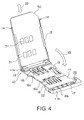
- the IC card 30 is inserted and fitted to the cover 12 in a direction depicted by an arrow 32.
- the cover 12 is rotated as depicted by an arrow 33 to be overlapped onto the housing 11.
- the cover shaft portions 13 are located at a position nearest to the one end 11a of the housing 11.
- the cover 12 is pressed downward and forced to slide towards the other end 11b of the housing 11. Then, the card-side contacting portions 31 are brought into press contact with the contact-side contacting portions 16a and the cover locking portions 14 are inserted below the locking plates 22.
- the cover 12 is lifted up under restoring force of the cover holding spring 19.
- the IC card 30 is properly connected to the connector 10.
- each of the cover locking portions 14 is engaged with a Z-direction engaging portion 22b of the locking plate 22 in the direction Z and with a Y-direction engaging portion 22c in the direction Y, irrespective of whether the IC card 30 is connected or not.
- the Z-direction and the Y-direction engaging portions 22b and 22c defines a recess portion 22d opened in the direction Z.
- the cover locking portion 14 is fitted to the recess portion 22d when engaged with the Z-direction engaging portion 22b.
- the cover 12 is pressed downward by a finger 40. Then, the cover 12 is slightly moved down and urges the cover holding spring 19. Therefore, the cover locking potions 14 are separated from the Z-direction engaging portions 22b of the locking plates 22.
- the cover 12 is pressed by the finger 40 towards the one end 11a of the housing 11. Then, the cover 12 slides along the housing 11 and the cover locking portions 14 move over the locking plates 22 to be completely separated from the housing locking portions 21. In the above-mentioned state, the cover 12 is in a closed state but the cover locking portions 14 are unlocked both in the direction Z and in the direction Y. Thus, the locked state of the mechanical locking arrangement mentioned above is released. When the cover 12 is forced to slid, appropriate click feeling is obtained under the action of the frictional locking arrangement.
- the cover 12 When the locked state of the mechanical locking arrangement is released, the cover 12 is slightly lifted up under restoring force of the cover holding spring 19 as illustrated in Fig. 8. Then, by picking the rotating end of the cover 12 by the finger 40 and lifting the rotating end as depicted by an arrow 43, the cover 12 can easily be opened.
- the cover 12 is rotated and opened. Then, it is possible to insert the IC card 30 into the cover 12 as illustrated in Fig. 4 and to remove the IC card 30 therefrom.
- each of the cover locking portions 14 and the locking plates 22 is made of metal.
- each of the cover locking portions 14 and the locking plates 22 may be made of an insulating substance such as resin.
- similar parts are designated by like reference numerals.
Landscapes
- Engineering & Computer Science (AREA)
- Physics & Mathematics (AREA)
- General Physics & Mathematics (AREA)
- Theoretical Computer Science (AREA)
- Artificial Intelligence (AREA)
- Computer Vision & Pattern Recognition (AREA)
- Coupling Device And Connection With Printed Circuit (AREA)
- Details Of Connecting Devices For Male And Female Coupling (AREA)
- Connector Housings Or Holding Contact Members (AREA)
Applications Claiming Priority (2)
| Application Number | Priority Date | Filing Date | Title |
|---|---|---|---|
| JP2002269675 | 2002-09-17 | ||
| JP2002269675A JP3711540B2 (ja) | 2002-09-17 | 2002-09-17 | 薄形コネクタ |
Publications (2)
| Publication Number | Publication Date |
|---|---|
| EP1400914A2 true EP1400914A2 (fr) | 2004-03-24 |
| EP1400914A3 EP1400914A3 (fr) | 2004-12-01 |
Family
ID=31944513
Family Applications (1)
| Application Number | Title | Priority Date | Filing Date |
|---|---|---|---|
| EP03255742A Withdrawn EP1400914A3 (fr) | 2002-09-17 | 2003-09-15 | Connecteur à profil fin avec un couvercle simple à manipuler et bloqué de façon sûre à l'état fermé |
Country Status (4)
| Country | Link |
|---|---|
| US (1) | US7063552B2 (fr) |
| EP (1) | EP1400914A3 (fr) |
| JP (1) | JP3711540B2 (fr) |
| CN (1) | CN1272877C (fr) |
Cited By (1)
| Publication number | Priority date | Publication date | Assignee | Title |
|---|---|---|---|---|
| EP1585051A1 (fr) * | 2004-04-06 | 2005-10-12 | Japan Aviation Electronics Industry, Limited | Connecteur de cartes comportant un élément de verrouillage afin de verrouiller un couvercle utilisé pour une connexion de masse |
Families Citing this family (15)
| Publication number | Priority date | Publication date | Assignee | Title |
|---|---|---|---|---|
| US20060270263A1 (en) * | 2002-11-19 | 2006-11-30 | Toshihisa Hirata | Memory card connector |
| US7083456B2 (en) * | 2004-03-17 | 2006-08-01 | Tyco Electronics Corporation | Electrical connector socket with loading caddy |
| JP4468193B2 (ja) * | 2005-01-27 | 2010-05-26 | 日本圧着端子製造株式会社 | カードコネクタ |
| JP4543005B2 (ja) * | 2006-05-15 | 2010-09-15 | ケル株式会社 | カードコネクタ |
| WO2008149850A1 (fr) | 2007-06-08 | 2008-12-11 | Konica Minolta Holdings, Inc. | Processus de production d'un élément d'affichage électrochimique et élément d'affichage électrochimique |
| JP4716383B2 (ja) * | 2007-10-10 | 2011-07-06 | 日本航空電子工業株式会社 | コネクタ |
| JP5188917B2 (ja) * | 2008-01-30 | 2013-04-24 | パナソニック株式会社 | コネクタ及び治具 |
| JP4573881B2 (ja) * | 2008-05-14 | 2010-11-04 | 日本航空電子工業株式会社 | コネクタ |
| US7963788B2 (en) * | 2008-09-01 | 2011-06-21 | Hon Hai Precision Ind. Co., Ltd | Electrical connector having datum block facilitating precise alignment |
| TWM354917U (en) * | 2008-10-14 | 2009-04-11 | Hon Hai Prec Ind Co Ltd | Electrical connector |
| TWM358427U (en) * | 2008-10-28 | 2009-06-01 | Hon Hai Prec Ind Co Ltd | Electrical connector |
| JP5110442B2 (ja) * | 2009-03-05 | 2012-12-26 | 山一電機株式会社 | カードコネクタ |
| TWM370223U (en) * | 2009-05-12 | 2009-12-01 | Hon Hai Prec Ind Co Ltd | Electrical connector |
| CN202503142U (zh) * | 2012-02-09 | 2012-10-24 | 番禺得意精密电子工业有限公司 | 电连接器 |
| JP7368069B2 (ja) * | 2019-09-02 | 2023-10-24 | 日本航空電子工業株式会社 | コネクタ |
Family Cites Families (16)
| Publication number | Priority date | Publication date | Assignee | Title |
|---|---|---|---|---|
| JPS61174185A (ja) | 1985-11-01 | 1986-08-05 | 京セラ株式会社 | 炭化物系セラミツク体の金属化方法 |
| ES2061121T3 (es) * | 1991-06-28 | 1994-12-01 | Molex Inc | Conectador de tarjeta de c i (circuitos integrados). |
| FR2707433B1 (fr) * | 1993-07-08 | 1995-08-18 | Pontarlier Connectors | Connecteur pour carte, en particulier pour carte électronique. |
| JPH09185973A (ja) * | 1995-12-28 | 1997-07-15 | Hirose Electric Co Ltd | 表面接点付カード用コネクタ |
| JP3213801B2 (ja) | 1996-09-27 | 2001-10-02 | ホシデン株式会社 | カードコネクタ |
| JP3250789B2 (ja) * | 1997-04-10 | 2002-01-28 | ヒロセ電機株式会社 | 表面接点をもつカード用電気コネクタ |
| US6149466A (en) * | 1997-05-13 | 2000-11-21 | Itt Manufacturing Enterprises, Inc. | Compact smart card electrical connector |
| US6106317A (en) | 1997-09-26 | 2000-08-22 | Thomas & Betts International, Inc. | IC chip card connector with pivotally and linearly movable cover |
| JPH11297415A (ja) * | 1998-04-03 | 1999-10-29 | Molex Inc | カード用コネクタ |
| DE69835506T2 (de) * | 1998-06-15 | 2007-04-05 | Molex Inc., Lisle | Verbinder für IC-Karten |
| JP2000260537A (ja) | 1999-02-16 | 2000-09-22 | Amphenol Tuchel Electronics Gmbh | スマートカードコネクタ |
| JP2000340280A (ja) * | 1999-05-31 | 2000-12-08 | Mitsumi Electric Co Ltd | メモリカード用コネクタ |
| JP2000340281A (ja) * | 1999-05-31 | 2000-12-08 | Mitsumi Electric Co Ltd | メモリカード用コネクタ |
| US6220882B1 (en) * | 1999-11-15 | 2001-04-24 | Molex Incorporated | IC card connector with release means |
| TW474466U (en) * | 2000-06-03 | 2002-01-21 | Hon Hai Prec Ind Co Ltd | Electronic card connector |
| US6663408B2 (en) * | 2001-02-08 | 2003-12-16 | Yamaichi Electronics Co., Ltd. | Card connector |
-
2002
- 2002-09-17 JP JP2002269675A patent/JP3711540B2/ja not_active Expired - Fee Related
-
2003
- 2003-09-15 EP EP03255742A patent/EP1400914A3/fr not_active Withdrawn
- 2003-09-15 US US10/662,898 patent/US7063552B2/en not_active Expired - Lifetime
- 2003-09-17 CN CNB03158974XA patent/CN1272877C/zh not_active Expired - Fee Related
Non-Patent Citations (1)
| Title |
|---|
| None |
Cited By (3)
| Publication number | Priority date | Publication date | Assignee | Title |
|---|---|---|---|---|
| EP1585051A1 (fr) * | 2004-04-06 | 2005-10-12 | Japan Aviation Electronics Industry, Limited | Connecteur de cartes comportant un élément de verrouillage afin de verrouiller un couvercle utilisé pour une connexion de masse |
| US7048566B2 (en) | 2004-04-06 | 2006-05-23 | Japan Aviation Electronics Industry, Limited | Card connector in which a locking member for locking a cover member is used for ground connection |
| CN100356634C (zh) * | 2004-04-06 | 2007-12-19 | 日本航空电子工业株式会社 | 卡连接器 |
Also Published As
| Publication number | Publication date |
|---|---|
| CN1272877C (zh) | 2006-08-30 |
| JP2004111125A (ja) | 2004-04-08 |
| JP3711540B2 (ja) | 2005-11-02 |
| US20040067673A1 (en) | 2004-04-08 |
| US7063552B2 (en) | 2006-06-20 |
| EP1400914A3 (fr) | 2004-12-01 |
| CN1495968A (zh) | 2004-05-12 |
Similar Documents
| Publication | Publication Date | Title |
|---|---|---|
| US7063552B2 (en) | Thin-profile connector having a cover which can be readily operated and reliably locked in a closed state | |
| US5938470A (en) | Half-fitting prevention connector | |
| EP2298611B1 (fr) | Commutateur coulissant pour appareil à boucle | |
| EP0926773B1 (fr) | Connecteur ayant un couvercle | |
| US5474461A (en) | Lever-operated connector | |
| EP1760841B1 (fr) | Dispositif de socle d' une carte à mémoire | |
| EP1198865B1 (fr) | Connecteur electrique pour carte a puce, comprenant un commutateur de verrouillage du couvercle porte-carte | |
| US8172592B2 (en) | Connector having a rotatable press member | |
| JP3250789B2 (ja) | 表面接点をもつカード用電気コネクタ | |
| EP1571734B1 (fr) | Dispositif de connexion ayant un élément de détection de l'engagement appelé assurance de position de connecteurs | |
| KR101909830B1 (ko) | 커넥터 부재 및 커넥터 | |
| US10804638B1 (en) | Safety shield assembly for power receptacle and related power receptacle | |
| US20070202750A1 (en) | Card connector | |
| US20030104726A1 (en) | Connector having a shielding shell provided with a locking portion | |
| EP2698879A1 (fr) | Connecteur | |
| GB2398184A (en) | Card connector locking cam | |
| KR100963726B1 (ko) | 커넥터 | |
| JP3213801B2 (ja) | カードコネクタ | |
| EP1548897B1 (fr) | Connecteur de cartes qui peut éviter des erreurs d'éjection et chute accidentelle d'une carte. | |
| JP3981942B2 (ja) | 電気コネクタ | |
| EP1585051B1 (fr) | Connecteur de cartes comportant un élément de verrouillage afin de verrouiller un couvercle utilisé pour une connexion de masse | |
| EP0991144A2 (fr) | Connecteur électrique avec un dispositif de transport | |
| TW201330394A (zh) | 連接器 | |
| US20070093106A1 (en) | Electrical connector with position means | |
| EP3644454B1 (fr) | Fiche de service |
Legal Events
| Date | Code | Title | Description |
|---|---|---|---|
| PUAI | Public reference made under article 153(3) epc to a published international application that has entered the european phase |
Free format text: ORIGINAL CODE: 0009012 |
|
| AK | Designated contracting states |
Kind code of ref document: A2 Designated state(s): AT BE BG CH CY CZ DE DK EE ES FI FR GB GR HU IE IT LI LU MC NL PT RO SE SI SK TR |
|
| AX | Request for extension of the european patent |
Extension state: AL LT LV MK |
|
| PUAL | Search report despatched |
Free format text: ORIGINAL CODE: 0009013 |
|
| AK | Designated contracting states |
Kind code of ref document: A3 Designated state(s): AT BE BG CH CY CZ DE DK EE ES FI FR GB GR HU IE IT LI LU MC NL PT RO SE SI SK TR |
|
| AX | Request for extension of the european patent |
Extension state: AL LT LV MK |
|
| 17P | Request for examination filed |
Effective date: 20050527 |
|
| AKX | Designation fees paid |
Designated state(s): DE FR GB |
|
| 17Q | First examination report despatched |
Effective date: 20100326 |
|
| STAA | Information on the status of an ep patent application or granted ep patent |
Free format text: STATUS: THE APPLICATION IS DEEMED TO BE WITHDRAWN |
|
| 18D | Application deemed to be withdrawn |
Effective date: 20160401 |