EP1400928A1 - Appareil pour le transcodage d'un format de données et méthode associée - Google Patents
Appareil pour le transcodage d'un format de données et méthode associée Download PDFInfo
- Publication number
- EP1400928A1 EP1400928A1 EP20030020780 EP03020780A EP1400928A1 EP 1400928 A1 EP1400928 A1 EP 1400928A1 EP 20030020780 EP20030020780 EP 20030020780 EP 03020780 A EP03020780 A EP 03020780A EP 1400928 A1 EP1400928 A1 EP 1400928A1
- Authority
- EP
- European Patent Office
- Prior art keywords
- predictive coefficient
- data
- predictive
- coefficient
- processing apparatus
- Prior art date
- Legal status (The legal status is an assumption and is not a legal conclusion. Google has not performed a legal analysis and makes no representation as to the accuracy of the status listed.)
- Withdrawn
Links
Images





Classifications
-
- H—ELECTRICITY
- H04—ELECTRIC COMMUNICATION TECHNIQUE
- H04N—PICTORIAL COMMUNICATION, e.g. TELEVISION
- H04N7/00—Television systems
- H04N7/01—Conversion of standards, e.g. involving analogue television standards or digital television standards processed at pixel level
-
- H—ELECTRICITY
- H04—ELECTRIC COMMUNICATION TECHNIQUE
- H04N—PICTORIAL COMMUNICATION, e.g. TELEVISION
- H04N7/00—Television systems
- H04N7/01—Conversion of standards, e.g. involving analogue television standards or digital television standards processed at pixel level
- H04N7/0135—Conversion of standards, e.g. involving analogue television standards or digital television standards processed at pixel level involving interpolation processes
-
- H—ELECTRICITY
- H04—ELECTRIC COMMUNICATION TECHNIQUE
- H04N—PICTORIAL COMMUNICATION, e.g. TELEVISION
- H04N19/00—Methods or arrangements for coding, decoding, compressing or decompressing digital video signals
- H04N19/10—Methods or arrangements for coding, decoding, compressing or decompressing digital video signals using adaptive coding
- H04N19/102—Methods or arrangements for coding, decoding, compressing or decompressing digital video signals using adaptive coding characterised by the element, parameter or selection affected or controlled by the adaptive coding
- H04N19/12—Selection from among a plurality of transforms or standards, e.g. selection between discrete cosine transform [DCT] and sub-band transform or selection between H.263 and H.264
- H04N19/122—Selection of transform size, e.g. 8x8 or 2x4x8 DCT; Selection of sub-band transforms of varying structure or type
-
- H—ELECTRICITY
- H04—ELECTRIC COMMUNICATION TECHNIQUE
- H04N—PICTORIAL COMMUNICATION, e.g. TELEVISION
- H04N19/00—Methods or arrangements for coding, decoding, compressing or decompressing digital video signals
- H04N19/10—Methods or arrangements for coding, decoding, compressing or decompressing digital video signals using adaptive coding
- H04N19/134—Methods or arrangements for coding, decoding, compressing or decompressing digital video signals using adaptive coding characterised by the element, parameter or criterion affecting or controlling the adaptive coding
- H04N19/162—User input
-
- H—ELECTRICITY
- H04—ELECTRIC COMMUNICATION TECHNIQUE
- H04N—PICTORIAL COMMUNICATION, e.g. TELEVISION
- H04N19/00—Methods or arrangements for coding, decoding, compressing or decompressing digital video signals
- H04N19/10—Methods or arrangements for coding, decoding, compressing or decompressing digital video signals using adaptive coding
- H04N19/169—Methods or arrangements for coding, decoding, compressing or decompressing digital video signals using adaptive coding characterised by the coding unit, i.e. the structural portion or semantic portion of the video signal being the object or the subject of the adaptive coding
- H04N19/17—Methods or arrangements for coding, decoding, compressing or decompressing digital video signals using adaptive coding characterised by the coding unit, i.e. the structural portion or semantic portion of the video signal being the object or the subject of the adaptive coding the unit being an image region, e.g. an object
- H04N19/176—Methods or arrangements for coding, decoding, compressing or decompressing digital video signals using adaptive coding characterised by the coding unit, i.e. the structural portion or semantic portion of the video signal being the object or the subject of the adaptive coding the unit being an image region, e.g. an object the region being a block, e.g. a macroblock
-
- H—ELECTRICITY
- H04—ELECTRIC COMMUNICATION TECHNIQUE
- H04N—PICTORIAL COMMUNICATION, e.g. TELEVISION
- H04N19/00—Methods or arrangements for coding, decoding, compressing or decompressing digital video signals
- H04N19/40—Methods or arrangements for coding, decoding, compressing or decompressing digital video signals using video transcoding, i.e. partial or full decoding of a coded input stream followed by re-encoding of the decoded output stream
-
- H—ELECTRICITY
- H04—ELECTRIC COMMUNICATION TECHNIQUE
- H04N—PICTORIAL COMMUNICATION, e.g. TELEVISION
- H04N19/00—Methods or arrangements for coding, decoding, compressing or decompressing digital video signals
- H04N19/50—Methods or arrangements for coding, decoding, compressing or decompressing digital video signals using predictive coding
- H04N19/587—Methods or arrangements for coding, decoding, compressing or decompressing digital video signals using predictive coding involving temporal sub-sampling or interpolation, e.g. decimation or subsequent interpolation of pictures in a video sequence
-
- H—ELECTRICITY
- H04—ELECTRIC COMMUNICATION TECHNIQUE
- H04N—PICTORIAL COMMUNICATION, e.g. TELEVISION
- H04N19/00—Methods or arrangements for coding, decoding, compressing or decompressing digital video signals
- H04N19/50—Methods or arrangements for coding, decoding, compressing or decompressing digital video signals using predictive coding
- H04N19/593—Methods or arrangements for coding, decoding, compressing or decompressing digital video signals using predictive coding involving spatial prediction techniques
-
- H—ELECTRICITY
- H04—ELECTRIC COMMUNICATION TECHNIQUE
- H04N—PICTORIAL COMMUNICATION, e.g. TELEVISION
- H04N19/00—Methods or arrangements for coding, decoding, compressing or decompressing digital video signals
- H04N19/60—Methods or arrangements for coding, decoding, compressing or decompressing digital video signals using transform coding
- H04N19/63—Methods or arrangements for coding, decoding, compressing or decompressing digital video signals using transform coding using sub-band based transform, e.g. wavelets
- H04N19/64—Methods or arrangements for coding, decoding, compressing or decompressing digital video signals using transform coding using sub-band based transform, e.g. wavelets characterised by ordering of coefficients or of bits for transmission
- H04N19/645—Methods or arrangements for coding, decoding, compressing or decompressing digital video signals using transform coding using sub-band based transform, e.g. wavelets characterised by ordering of coefficients or of bits for transmission by grouping of coefficients into blocks after the transform
-
- H—ELECTRICITY
- H04—ELECTRIC COMMUNICATION TECHNIQUE
- H04N—PICTORIAL COMMUNICATION, e.g. TELEVISION
- H04N19/00—Methods or arrangements for coding, decoding, compressing or decompressing digital video signals
- H04N19/85—Methods or arrangements for coding, decoding, compressing or decompressing digital video signals using pre-processing or post-processing specially adapted for video compression
-
- H—ELECTRICITY
- H04—ELECTRIC COMMUNICATION TECHNIQUE
- H04N—PICTORIAL COMMUNICATION, e.g. TELEVISION
- H04N7/00—Television systems
- H04N7/01—Conversion of standards, e.g. involving analogue television standards or digital television standards processed at pixel level
- H04N7/0135—Conversion of standards, e.g. involving analogue television standards or digital television standards processed at pixel level involving interpolation processes
- H04N7/0145—Conversion of standards, e.g. involving analogue television standards or digital television standards processed at pixel level involving interpolation processes the interpolation being class adaptive, i.e. it uses the information of class which is determined for a pixel based upon certain characteristics of the neighbouring pixels
Definitions
- the present invention relates to a data processing apparatus and method, a recording medium, and a program. More particularly, the present invention relates to a data processing apparatus and method, recording medium, and program suitable for transforming input data into data of another format, and transforming the resulting data into an orthogonally transformed signal.
- NTSC National Television System Committee
- a decoder for such signals is typically configured so as to allow for separation of the luminance signals (Y) and the chroma signals (C) (Y/C separation) (see, for example, Japanese Unexamined Patent Application Publication No. 2000-138949).
- MPEG Motion Picture Experts Group
- DCT Discrete Cosine Transform
- the configuration of a decoder for decoding an encoded signal must correspond to the configuration (processing scheme) of an encoder.
- the present invention is provided to decode an input signal by way of a single apparatus which generates signals having two or more different formats without increasing the size and/or complexity of the apparatus.
- data processing apparatus of the present invention includes a first storing means for storing a first predictive coefficient obtained by learning.
- An instructing means instructs conversion of the first predictive coefficient
- a first calculating means calculates a second predictive coefficient from the first predictive coefficient stored by the first storing means according to a predetermined transform method when conversion is instructed by the instructing means.
- the first calculating means calculates and outputs the second predictive coefficient when conversion is instructed by the instructing means, and outputs the first predictive coefficient without calculation of the second predictive coefficient when conversion is not instructed by the instructing means.
- the data processing apparatus may further include second storing means for storing the first predictive coefficient or second predictive coefficient output by the first calculating means.
- the exemplary data processing apparatus may further include first extracting means for extracting from the input data first data based on which a class is determined, a determining means for determining the class based on the first data extracted by the first extracting means, a second extracting means for extracting second data calculated from the input data; and third calculating means for calculating output data based on the second data extracted by the second extracting means and the first predictive coefficient or second predictive coefficient stored by the second storing means.
- the second storing means may supply the first predictive coefficient or second predictive coefficient corresponding to the class determined by the determining means to the third calculating means.
- the first predictive coefficient may be a predictive coefficient determined for each class based on third data serving as a student signal corresponding to the input data and fourth data serving as a teacher signal corresponding to the output data.
- the input data may be composite signal data
- the output data can be component signal data or data obtained by converting the component signal data according to the transform method.
- the data processing apparatus may further include decoding means for selecting one of data input from the outside and the output data generated by the third calculating means and for decoding the selected one.
- the instructing means may further instruct the transform method, and the first calculating means can calculate the second predictive coefficient from the first predictive coefficient stored by the first storing means according to the transform method instructed by the instructing means.
- the first calculating means may include third storing means for storing a transform formula corresponding to the transform method and for selecting the transform formula according to the transform method instructed by said instructing means, and can calculate the second predictive coefficient from the first predictive coefficient based on the transform formula stored by the third storing means.
- the third storing means may store a transform formula corresponding to an orthogonal transform as the transform formula corresponding to the transform method.
- An exemplary data processing method of the present invention includes an instructing step of instructing conversion of a first predictive coefficient which is stored and which is obtained by learning, and a calculating step of calculating a second predictive coefficient from the stored first predictive coefficient according to a predetermined transform method when conversion is instructed in the instructing step.
- An exemplary program of a recording medium of the present invention includes an instructing step of instructing conversion of a first predictive coefficient which is stored and which is obtained by learning, and a calculating step of calculating a second predictive coefficient from the stored first predictive coefficient according to a predetermined transform method when conversion is instructed in the instructing step.
- An exemplary program of the present invention includes a computer executable for instructing conversion of a first predictive coefficient which is stored and which is obtained by learning, and a calculating step of calculating a second predictive coefficient from the stored first predictive coefficient according to a predetermined transform method when conversion is instructed in the instructing step.
- a second predictive coefficient is calculated from the stored first predictive coefficient according to a predetermined transform method.
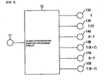
- FIG 1 is a diagram showing an exemplary structure of an image information transformation system in accordance with an embodiment of the invention
- FIG 2 is a high level block diagram showing an exemplary structure of a class categorization adaptive processing circuit shown in Fig. 1;
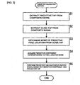
- FIG 3 is a flowchart showing a predictive calculation process of the class categorization adaptive processing circuit shown in Fig. 2;
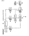
- FIG 4 is a high level block diagram showing an exemplary structure of a learning apparatus
- FIG 5 is a flowchart illustrating a seed coefficient determination process of the learning apparatus shown in Fig. 4;
- FIG 6 is a flowchart illustrating the seed coefficient determination process of the learning apparatus shown in Fig. 4;
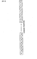
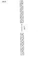
- FIG 7 is a diagram showing the structure of blocks of a teacher signal and predictive taps
- FIG 8 is a diagram showing the structure of blocks of a teacher signal and blocks of a Hadamard transformed signal
- FIG 9 is a diagram showing the structure of blocks of a teacher signal and blocks of a DCT signal
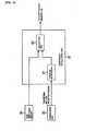
- FIG 10 is a high level block diagram showing the structure of a coefficient calculation unit shown in Fig. 2;
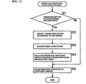
- FIG 11 is a flowchart for illustrating a predictive coefficient calculation process of the coefficient calculation unit shown in Fig. 10;
- FIG 12 is a high level block diagram showing the structure of an image information transformation apparatus.
- FIG 13 is a block diagram showing an exemplary structure of a computer system according to an embodiment of the present invention.
- FIG. 1 shows the configuration of an image information transformation system according to an exemplary embodiment of the present invention.
- the image information transformation system includes an input terminal 11 to which a composite signal may be input (for example, an NFSC signal), a class categorization adaptive processing circuit 12, output terminals 13A through 15A from which a luminance signal Y, a color-difference signal R-Y, and a color-difference signal B-Y are output, respectively.
- Terminals 13B through 15B provide output signals T(Y), T(R-Y), and T(B-Y) obtained by performing an orthogonal transformation on the luminance signal Y, the color-difference signal R-Y, and the color-difference signal B-Y, respectively.
- the composite signal input from the input terminal 11 is supplied to the class categorization adaptive processing circuit 12 for conversion into component signals (i.e., the luminance signal Y, color-difference signal R-Y, and color-difference signal B-Y, or conversion into the orthogonal transform signals T(Y), T(R-Y), and T(B-Y) of the NTSC signal), obtained by transforming the component signals.
- the transformation is orthogonal.
- the component signals are output from the output terminals 13A through 15A or the output terminals 13B through 15B.
- the output terminals 13A through 15A and the output terminals 13B through 15B may be common.
- Fig. 2 is a block diagram showing an exemplary structure of the class categorization adaptive processing circuit 12.
- the input composite signal is supplied to a block extraction unit 31 and a block extraction unit 34.
- the block extraction unit 31 extracts pixel data (class taps) of predesignated blocks from the supplied composite signal, and outputs the extracted data to a pixel-location-mode output unit 32.
- the pixel-location-mode output unit 32 outputs a mode (class) of the pixel location at which a predictive value is determined from the input pixel data (class taps) of the blocks, and supplies it to a coefficient memory 33.
- a seed coefficient memory 36 stores a seed coefficient (the details thereof are described below with reference to Figure 4) in advance.
- a coefficient calculation unit 37 calculates a predictive coefficient from the seed coefficient supplied from the seed coefficient memory 36 based on a transform method selection signal corresponding to a transform method of a designation unit 38.
- the coefficient memory 33 stores the coefficient calculated by the coefficient calculation unit 37.
- the coefficient memory 33 selects a predictive coefficient corresponding to the pixel location mode, and supplies the selected coefficient to a predictive calculation unit 35.
- the block extraction unit 34 extracts pixel data (hereinafter referred to as "predictive taps") of blocks necessary for predictive generation of a component signal from the input composite signal, and outputs the extracted predictive taps to the predictive calculation unit 35.
- the predictive calculation unit 35 performs predictive calculation using the predictive taps input from the block extraction unit 34 and the predictive coefficient input from the coefficient memory 33, and outputs a component signal or outputs a signal (transformed component signal) obtained by orthogonally transforming the component signal.
- step S1 the block extraction unit 34 extracts predictive taps from the composite signal.
- step S2 the block extraction unit 31 extracts class taps from the composite signal.
- step S3 the pixel-location-mode output unit 32 determines from the class taps the mode of a pixel location at which a predictive value is determined (the details thereof are described below with reference to Fig. 7).
- step S4 the predictive calculation unit 35 acquires a predictive coefficient corresponding to the pixel location mode from the coefficient memory 33.
- the coefficient memory 33 has a predetermined predictive coefficient, which is actually used, stored therein.
- step S5 the predictive calculation unit 35 performs a predictive calculation on an output signal based on the input predictive coefficient and predictive taps, and the process is complete.
- Fig. 4 illustrates an example structure of a learning apparatus 50 for learning a seed coefficient for the luminance signal Y to be stored in the seed coefficient memory 36.
- component signal serving as a "teacher signal” is formed of a set of signals including the luminance signal Y, the color-difference signal R-Y, and the color-difference signal B-Y This teacher signal is input to the learning apparatus 50, and is then supplied to a block extraction unit 51 and an NTSC encoder 52.
- the color difference signal R-Y is supplied to the block extraction unit 51 and the luminance signal Y is not supplied to the block extraction unit 51.
- the color difference signal B-Y is supplied to the block extraction unit 51 and the luminance signal Y is not supplied to the block extraction unit 51.
- the block extraction unit 51 extracts data of a predesignated block region from the input luminance signal (Y), and outputs the extracted data to an internal-block data output unit 55.
- the NTSC encoder 52 encodes the input teacher signal to generate an NTSC composite signal serving as a "student signal,” and outputs the resulting signal to a block extraction unit 53 and a block extraction unit 56.
- the block extraction unit 53 extracts class taps from the supplied student signal, and outputs the extracted class taps to a pixel-location-mode output unit 54.
- the pixel-location-mode output unit 54 outputs a pixel location mode from the input class taps, and supplies it to the internal-block data output unit 55 and a normal equation generation unit 57.
- the internal-block data output unit 55 outputs pixel data of the luminance signal (Y) input from the block extraction unit 51 corresponding to the pixel location mode input from the pixel-location-mode output unit 54 to the normal equation generation unit 57.
- the block extraction unit 56 extracts predictive taps from the blocks of the input student signal, and outputs the extracted predictive taps to the normal equation generation unit 57.
- the normal equation generation unit 57 generates, for each pixel location mode input from the pixel-location-mode output unit 54, a normal equation from the pixel data of the teacher signal input from the internal-block data output unit 55 and the predictive taps of the student signal input from the block extraction unit 56, and outputs the generated normal equation to a coefficient determination unit 58.
- the coefficient determination unit 58 determines a coefficient (seed coefficient) from the supplied normal equation, and stores the seed coefficient in the seed coefficient memory 36 (Fig. 2).
- step S31 the block extraction unit 51 extracts data of given blocks (predesignated blocks) from a luminance (Y) signal.
- step S32 the NTSC encoder 52 encodes the teacher signal to generate an NTSC composite signal (student signal).
- step S33 the block extraction unit 53 extracts class taps from the student signal (encoded teacher signal).
- step S34 the pixel-location-mode output unit 54 determines a pixel location mode from the class taps.
- step S35 from the data of the given blocks of the teacher signal supplied from the block extraction unit 51, the internal-block data output unit 55 extracts pixel data of the blocks of the luminance signal (Y) corresponding to the pixel location mode.
- step S36 the block extraction unit 56 extracts predictive taps from the student signal.
- step S37 the normal equation generation unit 57 generates a normal equation for each pixel location mode based on the predictive taps and the pixel data of the blocks of the luminance signal (Y).
- step S38 the coefficient determination unit 58 calculates the normal equation to determine a seed coefficient.
- step S39 the coefficient determination unit 58 stores the determined seed coefficient in the seed coefficient memory 36, and the process ends.
- eight normal equations are generated by the following formula:
- y indicates the pixel value of a teacher signal
- x indicates the pixel value of a predictive tap.
- a denotes the seed coefficient
- a normal equation corresponding to a pixel location mode is generated, and by calculating the finally determined normal equation, the seed coefficient (a) is determined. If the number of generated normal equations is insufficient for determining the seed coefficient (a), the normal equations are calculated using, for example, a least square method to determine the seed coefficient (a).
- y 1 ' through y 8 ' denote the values obtained by performing an Hadamard transform on the pixel values y 1 through y 8 of the teacher signal blocks.
- the values y 1 ' through y 8 ' are given by the following formula:
- y 1 " through y 8 " denote the values obtained by performing DCT on the pixel values y 1 through y 8 of the teacher signal blocks.
- the values y 1 " through y 8 " are given by the following formula:
- transformed signals of the pixel values y 1 through y 8 of the teacher signal blocks (Hadamard transformed signals y 1 ' through y 8 ' or DCT signals y 1 " through y 8 ") are represented by the linear sum of the pixel values y 1 through y 8 of the teacher signal.
- the predictive coefficient of the transformed teacher signal in this case, y 1 ' through y 8 ' or y 1 " through y 8 " can be determined from the predictive coefficient of the pixel values y 1 through y 8 of the teacher signal blocks.
- y 1 ' is given by the following formula:
- y' 1 1 8 (y 1 +y 2 +y 3 +y 4 +y 5 +y 6 +y 7 +y 8 )
- the predictive coefficient of y 1 ' is given by the following formula:
- the predictive coefficients (a) through (h) for prediction of y 1 " through y 8 " of a given student signal are given by the following formula using the predictive coefficients a through h for prediction of y 1 through y 8 :
- the coefficient calculation unit 37 of the class categorization adaptive processing circuit 12 shown in Fig. 2 has the structure shown in Fig. 10 is able to determine coefficients (predictive coefficients) for predictive calculation on an input signal from the seed coefficients.
- a transform matrix memory 91 has transform matrices for various transformations stored therein in advance. For example, a transform matrix for Hadamard transform given in Formula (8) or a transform matrix for DCT given in Formula (9) is stored.
- the transform matrix memory selects a transform matrix corresponding to the transform method selection signal from the stored transform matrices, and outputs the selected one to a calculation unit 92.
- the seed coefficient memory 36 outputs the seed coefficient stored and determined by the learning apparatus 50 to a calculation unit 92.
- the calculation unit 92 determines a predictive coefficient based on the input transform matrix and seed coefficient, and outputs it to the coefficient memory 33.
- the learning apparatus 50 determines the seed coefficient of the Y signal of the component signal (teacher signal) has been discussed, the seed coefficients of the color-difference signals R-Y and B-Y of the component signals can also be determined by a similar process.
- the transform method selection signal output from the designation unit 38 is a signal for selecting whether or not that transform matrix is used.
- a predictive coefficient calculation process of the coefficient calculation unit 37 is described below in detail with reference to the flowchart of Fig. 11. This process is executed according to a user instruction before the predictive calculation process shown in Fig. 3 is executed.
- a designation unit 38 operates to specify which method of a plurality of transform methods is used. In the exemplary embodiment, this operation is designated by user input, however, those skilled in the art will recognize that such selection may be provided automatically in response to one or more system parameters.
- the transform matrix memory 91 determines, based on the designation, whether or not a transform method selection signal has been input from the designation unit 38. If it is determined that a transform method selection signal has been input, the process proceeds to step S52, in which the transform matrix memory 91 selects a predetermined transform matrix from the stored transform matrices according to the transform method selection signal.
- the transform matrix (Formula (8)) for Hadamard transform or the transform matrix (Formula (9)) for DCT is selected.
- the above transforms are illustrative examples rather than an exhaustive list of possible transforms as known to those skilled in the art.
- step S53 the calculation unit 92 acquires the seed coefficient from the seed coefficient memory 36.
- step S54 the calculation unit 92 determines the predictive coefficient based on the selected transform matrix and the acquired seed coefficient.
- the coefficients (a) through (h) are determined based on Formula (8) when the transform matrix for Hadamard transform is selected, and the coefficients (a) through (h) are determined based on Formula (9) when the transform matrix for DCT is selected.
- step S55 the calculation unit 92 stores the determined predictive coefficients in the coefficient memory 33.
- step S51 If it is determined in step S51 that no transform method selection signal has been input, this means that no instruction of transform has been performed, and the process proceeds to step S55, in which the transform matrix memory 91 stores the seed coefficient in the coefficient memory 33 without change.
- the predictive calculation process described with reference to the flowchart of Fig. 3 is performed using the predictive coefficient stored in the coefficient memory 33.
- the NTSC component signals i.e., the luminance signal Y, the color-difference signal R-Y, and the color-difference signal B-Y
- the transform signals T(Y), T(R-Y), and T(B-Y) obtained by performing an Hadamard transform on the component signals are output from the output terminals 13B through 15B; and when the transform matrix for DCT has been selected, the transform signals T(Y), T(R-Y), and T(B-Y) obtained by performing DCT on the component signals are output from the output terminals 13B through 15B.
- a composite signal can be converted into component signals or can be directly converted into signals obtained by performing an orthogonal transform on the component signals. Furthermore, it is not necessary to learn predictive coefficients for each transform method, in which case the capacity of a memory for storing predictive coefficients can be reduced compared to the case where predictive coefficients for all different transform methods must be stored. Furthermore, it is only required to change transform matrices stored in the transform matrix memory 91 in order to acquire predictive coefficients for different transform methods, and the transform matrices can be easily changed and/or updated.
- the transform matrix memory 91 may be an externally rewritable memory so that the content of the stored transform matrices can be modified.
- the predictive tap is divided into 3 x 8 blocks and the teacher signal is divided into 1 x 8 blocks; however, those skilled in the art will recognize that such block division is exemplary only and that alternative groupings are possible the way by which these are divided into blocks may be arbitrary.
- an NTSC signal is directly converted into signals obtained by performing an orthogonal transform such as Hadamard transform or DCT on component signals (i.e., the luminance signal Y, the color-difference signal R-Y, and the color-difference signal B-Y).
- an orthogonal transform such as Hadamard transform or DCT
- component signals i.e., the luminance signal Y, the color-difference signal R-Y, and the color-difference signal B-Y.
- any signal other than an NTSC signal or a video signal may be converted as long as teacher signal blocks and student signal blocks have one-to-one correspondence and each block is independent from other blocks during the learning operation of the learning apparatus.
- Fig. 12 is a block diagram showing an example structure of an image information transformation apparatus including the above-described class categorization adaptive processing circuit 12 equipped with a decoder.
- This image information transformation apparatus is constructed as, for example, a television receiver.
- an NTSC composite signal is input to the class categorization adaptive processing circuit 12.
- the class categorization adaptive processing circuit 12 directly converts the input NTSC signal into a DCT component signal, and outputs the resulting signal to an MPEG decoder 121.
- the MPEG decoder 121 decodes the input DCT component signal, and outputs a component signal.
- an MPEG signal is directly supplied to the MPEG decoder 121.
- the MPEG decoder 121 decodes the MPEG signal and outputs a component signal.
- this single decoder can be used to process signal encoded with various methods.
- an MPEG signal is used in the above-described example
- an image information transformation apparatus to which both another signal such as an Hadamard transformed signal and an NTSC signal are input may also be used.
- a decoder for performing the inverse Hadamard transform is used.
- sequence of processes may be executed by either hardware or software implementation.
- a program constituting the software is installed into a general-purpose computer or embodied in the carrier such as magnetic or optical disc or a radio frequency or audio frequency carrier wave.
- Fig. 13 shows an example structure of an embodiment of a computer 201 to which a program for executing the above-described sequence of processes is installed.
- the computer 201 includes a built-in CPU (Central Processing Unit) 202.
- An input/output interface 206 is connected to the CPU 202 via a bus 205.
- a ROM (Read Only Memory) 203 and a RAM (Random Access Memory) 204 are connected to the bus 205.
- a storage unit 209 such as a hard disk drive for storing a program or various data, and a communication unit 210 for communicating data over a variety of networks including the Internet are connected to the input/output interface 206.
- a drive 211 for reading and writing data from and to a recording medium such as a removable memory 212 is also connected to the input/output interface 206, as required.
- An image information transformation program which causes the computer 201 to execute an operation as an image information transformation apparatus according to the present invention is offered to the computer 201 as is stored in the removable memory 212, and is read by the drive 211 and installed to the hard disk drive built in the storage unit 209.
- the information processing program installed to the storage unit 209 is loaded, according to an instruction of the CPU 202 corresponding to a user command input to the input unit 207, from the storage unit 209 to the RAM 204 in which it is executed.
- This recording medium is formed of not only a packaged media such as the removable memory 212 having a program stored therein, which is distributed separately from the apparatus to offer the program to users, as shown in Fig. 13, but also formed of the ROM 203 having a program recorded therein, a hard disk contained in the storage unit 209, or the like which is offered to users as is incorporated in the apparatus in advance.
- process steps describing a program which causes a computer to execute various functions of the invention are not necessarily performed in a time-series manner according to the order described in the flowcharts, and include a process performed in parallel or discrete manner (for example, a parallel process or an object-based process).
- input data can be converted into data of another format, and, particularly, can be readily converted into any of data of a plurality of formats.
- transform methods can be readily changed.
- signals encoded with a plurality of methods can be processed using a single decoder.
Landscapes
- Engineering & Computer Science (AREA)
- Multimedia (AREA)
- Signal Processing (AREA)
- Physics & Mathematics (AREA)
- Discrete Mathematics (AREA)
- General Physics & Mathematics (AREA)
- Compression Or Coding Systems Of Tv Signals (AREA)
- Compression, Expansion, Code Conversion, And Decoders (AREA)
- Television Systems (AREA)
Applications Claiming Priority (2)
| Application Number | Priority Date | Filing Date | Title |
|---|---|---|---|
| JP2002266328A JP4055203B2 (ja) | 2002-09-12 | 2002-09-12 | データ処理装置およびデータ処理方法、記録媒体、並びにプログラム |
| JP2002266328 | 2002-09-12 |
Publications (1)
| Publication Number | Publication Date |
|---|---|
| EP1400928A1 true EP1400928A1 (fr) | 2004-03-24 |
Family
ID=31944493
Family Applications (1)
| Application Number | Title | Priority Date | Filing Date |
|---|---|---|---|
| EP20030020780 Withdrawn EP1400928A1 (fr) | 2002-09-12 | 2003-09-12 | Appareil pour le transcodage d'un format de données et méthode associée |
Country Status (5)
| Country | Link |
|---|---|
| US (1) | US7424057B2 (fr) |
| EP (1) | EP1400928A1 (fr) |
| JP (1) | JP4055203B2 (fr) |
| KR (1) | KR100982766B1 (fr) |
| CN (1) | CN1275393C (fr) |
Cited By (1)
| Publication number | Priority date | Publication date | Assignee | Title |
|---|---|---|---|---|
| KR100982766B1 (ko) * | 2002-09-12 | 2010-09-16 | 소니 주식회사 | 데이터 처리 장치 및 그 방법, 컴퓨터 판독 가능한 매체 |
Families Citing this family (3)
| Publication number | Priority date | Publication date | Assignee | Title |
|---|---|---|---|---|
| JP4517300B2 (ja) * | 2006-01-06 | 2010-08-04 | ソニー株式会社 | 表示装置および表示方法、学習装置および学習方法、並びにプログラム |
| CN101238852B (zh) * | 2008-01-28 | 2010-09-01 | 吴忠尚 | 一种畜禽育肥增重的中药组合物及其制备方法 |
| CN102474268A (zh) * | 2009-08-06 | 2012-05-23 | 松下电器产业株式会社 | 编码方法、解码方法、编码装置及解码装置 |
Citations (24)
| Publication number | Priority date | Publication date | Assignee | Title |
|---|---|---|---|---|
| US4054909A (en) * | 1974-05-02 | 1977-10-18 | Fujitsu Ltd. | Method and system for bandwidth-compressed transmission of a video signal in the NTSC system |
| EP0597724A2 (fr) * | 1992-11-13 | 1994-05-18 | Sony Corporation | Appareil de codage et/ou décodage à haute efficacité |
| EP0635978A1 (fr) * | 1992-12-10 | 1995-01-25 | Sony Corporation | Convertisseur de signal-image |
| US5469216A (en) * | 1993-12-03 | 1995-11-21 | Sony Corporation | Apparatus and method for processing a digital video signal to produce interpolated data |
| EP0685800A2 (fr) * | 1994-05-28 | 1995-12-06 | Sony Corporation | Procédé et dispositif de traitement numérique de signal |
| US5488618A (en) * | 1993-06-29 | 1996-01-30 | Sony Corporation | Error detecting apparatus |
| US5495297A (en) * | 1993-07-29 | 1996-02-27 | Sony Corporation | Signal converting apparatus |
| US5598214A (en) * | 1993-09-30 | 1997-01-28 | Sony Corporation | Hierarchical encoding and decoding apparatus for a digital image signal |
| US5663764A (en) * | 1993-09-30 | 1997-09-02 | Sony Corporation | Hierarchical encoding and decoding apparatus for a digital image signal |
| EP0820197A2 (fr) * | 1996-07-17 | 1998-01-21 | Sony Corporation | Codage et décodage d'image par mappage de coéfficients correspondant à une information de classe des blocs de pixels |
| EP0820195A2 (fr) * | 1996-07-17 | 1998-01-21 | Sony Corporation | Méthode de codage d'image avec sous-échantillonnage et interpolation utilisant des classes de blocs de pixels |
| EP0851690A1 (fr) * | 1996-07-17 | 1998-07-01 | Sony Corporation | Dispositif et procede de traitement d'images et dispositif et procede de codage d'images |
| EP0890943A2 (fr) * | 1997-07-11 | 1999-01-13 | Nec Corporation | Système de codage et décodage de la parole |
| EP0895188A2 (fr) * | 1997-07-30 | 1999-02-03 | Sony Corporation | Procédé et appareil pour la mise à échelle d'images |
| US5912708A (en) * | 1996-12-26 | 1999-06-15 | Sony Corporation | Picture signal encoding device, picture signal encoding method, picture signal decoding device, picture signal decoding method, and recording medium |
| US5940539A (en) * | 1996-02-05 | 1999-08-17 | Sony Corporation | Motion vector detecting apparatus and method |
| US5966183A (en) * | 1995-03-22 | 1999-10-12 | Sony Corporation | Signal converter and signal conversion method |
| EP0951184A1 (fr) * | 1997-11-05 | 1999-10-20 | Sony Corporation | Procede de conversion de signaux numeriques et appareil de conversion de signaux numeriques |
| US6016164A (en) * | 1994-11-28 | 2000-01-18 | Sony Corporation | Image signal interpolating apparatus |
| EP0989748A2 (fr) * | 1998-08-24 | 2000-03-29 | Sony Corporation | Conversion de données d'images et processeur vidéo |
| EP1039755A2 (fr) * | 1999-03-25 | 2000-09-27 | Sony Corporation | Codeur d'images avec correction du code classe |
| US6134348A (en) * | 1996-10-04 | 2000-10-17 | Sony Corporation | Image processing apparatus and method |
| US6323905B1 (en) * | 1997-12-25 | 2001-11-27 | Sony Corporation | Picture conversion apparatus picture conversion method learning apparatus and learning method |
| US6438267B1 (en) * | 1997-12-19 | 2002-08-20 | Sony Corporation | Image compression method |
Family Cites Families (13)
| Publication number | Priority date | Publication date | Assignee | Title |
|---|---|---|---|---|
| JP3831955B2 (ja) * | 1995-05-12 | 2006-10-11 | ソニー株式会社 | クラス分類適応処理装置および方法 |
| US5852470A (en) * | 1995-05-31 | 1998-12-22 | Sony Corporation | Signal converting apparatus and signal converting method |
| US5781238A (en) * | 1995-07-28 | 1998-07-14 | Sony Corporation | Information signal encoding apparatus, encoding method thereof, information signal decoding method, and information signal record medium thereof |
| JP3522012B2 (ja) * | 1995-08-23 | 2004-04-26 | 沖電気工業株式会社 | コード励振線形予測符号化装置 |
| US6015154A (en) * | 1998-05-28 | 2000-01-18 | Hydra-Lock Corporation | Large displacement hydrostatic workpiece holder |
| DE69933339T8 (de) * | 1998-07-02 | 2007-09-13 | Nippon Telegraph And Telephone Corp. | Nachweisvorrichtung für kleine Kapazitätsänderungen |
| JP4099555B2 (ja) * | 1998-09-04 | 2008-06-11 | ソニー株式会社 | 画像情報変換装置 |
| JP4140091B2 (ja) * | 1998-09-14 | 2008-08-27 | ソニー株式会社 | 画像情報変換装置および画像情報変換方法 |
| JP4164912B2 (ja) * | 1998-09-30 | 2008-10-15 | ソニー株式会社 | 信号処理装置及び信号処理方法 |
| JP4457276B2 (ja) * | 2000-04-13 | 2010-04-28 | ソニー株式会社 | 画像処理装置および画像処理方法、並びに記録媒体 |
| JP4277446B2 (ja) | 2000-12-26 | 2009-06-10 | ソニー株式会社 | 情報信号処理装置、情報信号処理方法、画像信号処理装置およびそれを使用した画像表示装置、それに使用される係数種データ生成装置および生成方法、並びに記録媒体 |
| DE60239364D1 (de) | 2001-01-22 | 2011-04-14 | Sony Corp | Prozessor zum Umwandeln von Informationssignalen und entsprechendes Verfahren |
| JP4055203B2 (ja) * | 2002-09-12 | 2008-03-05 | ソニー株式会社 | データ処理装置およびデータ処理方法、記録媒体、並びにプログラム |
-
2002
- 2002-09-12 JP JP2002266328A patent/JP4055203B2/ja not_active Expired - Fee Related
-
2003
- 2003-09-08 KR KR1020030062671A patent/KR100982766B1/ko not_active Expired - Fee Related
- 2003-09-09 US US10/657,198 patent/US7424057B2/en not_active Expired - Fee Related
- 2003-09-12 CN CNB031581544A patent/CN1275393C/zh not_active Expired - Fee Related
- 2003-09-12 EP EP20030020780 patent/EP1400928A1/fr not_active Withdrawn
Patent Citations (29)
| Publication number | Priority date | Publication date | Assignee | Title |
|---|---|---|---|---|
| US4054909A (en) * | 1974-05-02 | 1977-10-18 | Fujitsu Ltd. | Method and system for bandwidth-compressed transmission of a video signal in the NTSC system |
| EP0597724A2 (fr) * | 1992-11-13 | 1994-05-18 | Sony Corporation | Appareil de codage et/ou décodage à haute efficacité |
| EP0635978A1 (fr) * | 1992-12-10 | 1995-01-25 | Sony Corporation | Convertisseur de signal-image |
| US5488618A (en) * | 1993-06-29 | 1996-01-30 | Sony Corporation | Error detecting apparatus |
| US5495297A (en) * | 1993-07-29 | 1996-02-27 | Sony Corporation | Signal converting apparatus |
| US5859667A (en) * | 1993-09-30 | 1999-01-12 | Sony Corporation | Hierarchical encoding and decoding apparatus for a digital image signal |
| US5598214A (en) * | 1993-09-30 | 1997-01-28 | Sony Corporation | Hierarchical encoding and decoding apparatus for a digital image signal |
| US5663764A (en) * | 1993-09-30 | 1997-09-02 | Sony Corporation | Hierarchical encoding and decoding apparatus for a digital image signal |
| US5469216A (en) * | 1993-12-03 | 1995-11-21 | Sony Corporation | Apparatus and method for processing a digital video signal to produce interpolated data |
| US5764305A (en) * | 1994-05-28 | 1998-06-09 | Sony Corporation | Digital signal processing apparatus and method |
| EP0685800A2 (fr) * | 1994-05-28 | 1995-12-06 | Sony Corporation | Procédé et dispositif de traitement numérique de signal |
| US5739873A (en) * | 1994-05-28 | 1998-04-14 | Sony Corporation | Method and apparatus for processing components of a digital signal in the temporal and frequency regions |
| US6016164A (en) * | 1994-11-28 | 2000-01-18 | Sony Corporation | Image signal interpolating apparatus |
| US5966183A (en) * | 1995-03-22 | 1999-10-12 | Sony Corporation | Signal converter and signal conversion method |
| US5940539A (en) * | 1996-02-05 | 1999-08-17 | Sony Corporation | Motion vector detecting apparatus and method |
| EP0820195A2 (fr) * | 1996-07-17 | 1998-01-21 | Sony Corporation | Méthode de codage d'image avec sous-échantillonnage et interpolation utilisant des classes de blocs de pixels |
| US20010031091A1 (en) * | 1996-07-17 | 2001-10-18 | Sony Corporation | Apparatus for and method of processing image and apparatus for and method of encoding image |
| EP0851690A1 (fr) * | 1996-07-17 | 1998-07-01 | Sony Corporation | Dispositif et procede de traitement d'images et dispositif et procede de codage d'images |
| EP0820197A2 (fr) * | 1996-07-17 | 1998-01-21 | Sony Corporation | Codage et décodage d'image par mappage de coéfficients correspondant à une information de classe des blocs de pixels |
| US6263105B1 (en) * | 1996-10-04 | 2001-07-17 | Sony Corporation | Image processing apparatus and method |
| US6134348A (en) * | 1996-10-04 | 2000-10-17 | Sony Corporation | Image processing apparatus and method |
| US5912708A (en) * | 1996-12-26 | 1999-06-15 | Sony Corporation | Picture signal encoding device, picture signal encoding method, picture signal decoding device, picture signal decoding method, and recording medium |
| EP0890943A2 (fr) * | 1997-07-11 | 1999-01-13 | Nec Corporation | Système de codage et décodage de la parole |
| EP0895188A2 (fr) * | 1997-07-30 | 1999-02-03 | Sony Corporation | Procédé et appareil pour la mise à échelle d'images |
| EP0951184A1 (fr) * | 1997-11-05 | 1999-10-20 | Sony Corporation | Procede de conversion de signaux numeriques et appareil de conversion de signaux numeriques |
| US6438267B1 (en) * | 1997-12-19 | 2002-08-20 | Sony Corporation | Image compression method |
| US6323905B1 (en) * | 1997-12-25 | 2001-11-27 | Sony Corporation | Picture conversion apparatus picture conversion method learning apparatus and learning method |
| EP0989748A2 (fr) * | 1998-08-24 | 2000-03-29 | Sony Corporation | Conversion de données d'images et processeur vidéo |
| EP1039755A2 (fr) * | 1999-03-25 | 2000-09-27 | Sony Corporation | Codeur d'images avec correction du code classe |
Non-Patent Citations (1)
| Title |
|---|
| JENS-RAINER OHM: "Digital Bildcodierung; Repräsentation, Kompression und übertragung von Bildsignalen", 1995, SPRINGER, BERLIN, DE, ISBN: 3-540-58579-6, XP002267166, 021758 * |
Cited By (1)
| Publication number | Priority date | Publication date | Assignee | Title |
|---|---|---|---|---|
| KR100982766B1 (ko) * | 2002-09-12 | 2010-09-16 | 소니 주식회사 | 데이터 처리 장치 및 그 방법, 컴퓨터 판독 가능한 매체 |
Also Published As
| Publication number | Publication date |
|---|---|
| US20040126022A1 (en) | 2004-07-01 |
| CN1494220A (zh) | 2004-05-05 |
| KR20040024488A (ko) | 2004-03-20 |
| JP2004104636A (ja) | 2004-04-02 |
| KR100982766B1 (ko) | 2010-09-16 |
| JP4055203B2 (ja) | 2008-03-05 |
| US7424057B2 (en) | 2008-09-09 |
| CN1275393C (zh) | 2006-09-13 |
Similar Documents
| Publication | Publication Date | Title |
|---|---|---|
| CN109076226B (zh) | 图像处理装置和方法 | |
| KR100655837B1 (ko) | 데이터 처리 장치, 데이터 처리 방법, 및 그에 대한 기록매체 | |
| JP3748088B2 (ja) | 画像処理装置および方法、並びに学習装置および方法 | |
| US8037509B2 (en) | Signal processing system and method, signal processing apparatus and method, recording medium, and program | |
| EP0820196A2 (fr) | Codage hiérarchique d'image | |
| US6563946B2 (en) | Image processing apparatus and method | |
| JP2000244935A (ja) | 画像データ圧縮方法 | |
| US6047089A (en) | Image compression and expansion device | |
| JP2006141016A (ja) | 画像データの符号化方法、画像データの復号化方法、及びその装置、並びに記録媒体 | |
| US7424057B2 (en) | Data format transcoding apparatus and associated method | |
| EP0820198B1 (fr) | Appareil et procédé pour le codage et décodage d'image | |
| JP4193871B2 (ja) | 画像処理装置、画像処理方法、およびプログラム | |
| US6226445B1 (en) | Image compression and expansion device | |
| US6445870B1 (en) | Image compression and expansion device | |
| JP3844031B2 (ja) | 画像符号化装置および画像符号化方法、並びに、画像復号装置および画像復号方法 | |
| JPH08307835A (ja) | クラス分類適応処理装置および方法 | |
| JP4154902B2 (ja) | 画像処理装置および画像処理方法、並びにプログラムおよび記録媒体 | |
| US20090226145A1 (en) | Data processing device, data processing method, and program | |
| KR100567710B1 (ko) | 화상코딩장치,화상코딩방법,화상디코딩방법,화상디코딩장치,화상데이타전송방법및기록매체 | |
| CN119484827A (zh) | 使用色度量化参数表的图像解码方法及其设备 | |
| JP2000102006A (ja) | 画像データ変換装置及び画像データ変換方法 | |
| JP4154903B2 (ja) | 画像処理装置および画像処理方法、並びにプログラムおよび記録媒体 | |
| JP4566877B2 (ja) | 画像処理装置および方法 | |
| JP4645401B2 (ja) | 記録装置および方法、並びにプログラム | |
| EP1298934A1 (fr) | Appareil et procédé pour le codage et décodage d'images |
Legal Events
| Date | Code | Title | Description |
|---|---|---|---|
| PUAI | Public reference made under article 153(3) epc to a published international application that has entered the european phase |
Free format text: ORIGINAL CODE: 0009012 |
|
| AK | Designated contracting states |
Kind code of ref document: A1 Designated state(s): AT BE BG CH CY CZ DE DK EE ES FI FR GB GR HU IE IT LI LU MC NL PT RO SE SI SK TR |
|
| AX | Request for extension of the european patent |
Extension state: AL LT LV MK |
|
| 17P | Request for examination filed |
Effective date: 20040728 |
|
| 17Q | First examination report despatched |
Effective date: 20041018 |
|
| AKX | Designation fees paid |
Designated state(s): DE FR GB |
|
| STAA | Information on the status of an ep patent application or granted ep patent |
Free format text: STATUS: THE APPLICATION IS DEEMED TO BE WITHDRAWN |
|
| 18D | Application deemed to be withdrawn |
Effective date: 20140401 |