EP1400932A1 - Procédé et dispositif de stockage et d'extraction automatique d'articles individuels - Google Patents
Procédé et dispositif de stockage et d'extraction automatique d'articles individuels Download PDFInfo
- Publication number
- EP1400932A1 EP1400932A1 EP03405674A EP03405674A EP1400932A1 EP 1400932 A1 EP1400932 A1 EP 1400932A1 EP 03405674 A EP03405674 A EP 03405674A EP 03405674 A EP03405674 A EP 03405674A EP 1400932 A1 EP1400932 A1 EP 1400932A1
- Authority
- EP
- European Patent Office
- Prior art keywords
- storage
- goods
- area
- column
- stored
- Prior art date
- Legal status (The legal status is an assumption and is not a legal conclusion. Google has not performed a legal analysis and makes no representation as to the accuracy of the status listed.)
- Withdrawn
Links
- 238000000034 method Methods 0.000 title claims abstract description 148
- 238000003860 storage Methods 0.000 claims abstract description 816
- 230000008569 process Effects 0.000 claims abstract description 75
- 238000012546 transfer Methods 0.000 claims abstract description 45
- 238000005192 partition Methods 0.000 claims description 108
- 238000012384 transportation and delivery Methods 0.000 claims description 75
- 239000000969 carrier Substances 0.000 claims description 53
- 230000032258 transport Effects 0.000 claims description 26
- 238000001514 detection method Methods 0.000 claims description 22
- 238000004806 packaging method and process Methods 0.000 claims description 12
- 230000009897 systematic effect Effects 0.000 claims description 12
- 238000003780 insertion Methods 0.000 claims description 6
- 230000037431 insertion Effects 0.000 claims description 6
- 239000000203 mixture Substances 0.000 claims description 5
- 238000013523 data management Methods 0.000 claims description 3
- 230000000630 rising effect Effects 0.000 claims description 2
- 238000013500 data storage Methods 0.000 claims 1
- 230000001960 triggered effect Effects 0.000 claims 1
- 238000012946 outsourcing Methods 0.000 description 24
- 230000007246 mechanism Effects 0.000 description 17
- 230000008901 benefit Effects 0.000 description 15
- 230000006870 function Effects 0.000 description 12
- 230000004888 barrier function Effects 0.000 description 7
- 238000011161 development Methods 0.000 description 7
- 230000018109 developmental process Effects 0.000 description 7
- 230000003287 optical effect Effects 0.000 description 6
- 244000144619 Abrus precatorius Species 0.000 description 4
- 238000012937 correction Methods 0.000 description 4
- 230000000694 effects Effects 0.000 description 4
- 238000005516 engineering process Methods 0.000 description 4
- 238000007726 management method Methods 0.000 description 4
- 235000013361 beverage Nutrition 0.000 description 3
- 230000007547 defect Effects 0.000 description 3
- 238000013461 design Methods 0.000 description 3
- 238000012423 maintenance Methods 0.000 description 3
- 230000035515 penetration Effects 0.000 description 3
- 238000012545 processing Methods 0.000 description 3
- 238000000926 separation method Methods 0.000 description 3
- 206010021639 Incontinence Diseases 0.000 description 2
- 239000012141 concentrate Substances 0.000 description 2
- 238000010276 construction Methods 0.000 description 2
- 238000001816 cooling Methods 0.000 description 2
- 238000009434 installation Methods 0.000 description 2
- 239000002904 solvent Substances 0.000 description 2
- 230000009471 action Effects 0.000 description 1
- 230000003213 activating effect Effects 0.000 description 1
- 230000008859 change Effects 0.000 description 1
- 238000011109 contamination Methods 0.000 description 1
- 230000001419 dependent effect Effects 0.000 description 1
- 230000005484 gravity Effects 0.000 description 1
- 230000006872 improvement Effects 0.000 description 1
- 239000012535 impurity Substances 0.000 description 1
- 238000001764 infiltration Methods 0.000 description 1
- 230000008595 infiltration Effects 0.000 description 1
- 230000000977 initiatory effect Effects 0.000 description 1
- 238000007689 inspection Methods 0.000 description 1
- 230000010354 integration Effects 0.000 description 1
- 230000003993 interaction Effects 0.000 description 1
- 238000012432 intermediate storage Methods 0.000 description 1
- 239000007788 liquid Substances 0.000 description 1
- 230000005923 long-lasting effect Effects 0.000 description 1
- 230000007257 malfunction Effects 0.000 description 1
- 239000000463 material Substances 0.000 description 1
- 238000005259 measurement Methods 0.000 description 1
- 238000012986 modification Methods 0.000 description 1
- 230000004048 modification Effects 0.000 description 1
- 230000000149 penetrating effect Effects 0.000 description 1
- 239000000843 powder Substances 0.000 description 1
- 230000033764 rhythmic process Effects 0.000 description 1
- 230000035939 shock Effects 0.000 description 1
- 238000004513 sizing Methods 0.000 description 1
- 238000000638 solvent extraction Methods 0.000 description 1
- 230000003068 static effect Effects 0.000 description 1
- 238000012360 testing method Methods 0.000 description 1
- 238000012549 training Methods 0.000 description 1
- 238000011144 upstream manufacturing Methods 0.000 description 1
- 238000005406 washing Methods 0.000 description 1
Images





Classifications
-
- G—PHYSICS
- G07—CHECKING-DEVICES
- G07F—COIN-FREED OR LIKE APPARATUS
- G07F11/00—Coin-freed apparatus for dispensing, or the like, discrete articles
- G07F11/02—Coin-freed apparatus for dispensing, or the like, discrete articles from non-movable magazines
- G07F11/04—Coin-freed apparatus for dispensing, or the like, discrete articles from non-movable magazines in which magazines the articles are stored one vertically above the other
- G07F11/16—Delivery means
- G07F11/165—Delivery means using xyz-picker or multi-dimensional article picking arrangements
-
- G—PHYSICS
- G07—CHECKING-DEVICES
- G07F—COIN-FREED OR LIKE APPARATUS
- G07F11/00—Coin-freed apparatus for dispensing, or the like, discrete articles
- G07F11/62—Coin-freed apparatus for dispensing, or the like, discrete articles in which the articles are stored in compartments in fixed receptacles
-
- G—PHYSICS
- G07—CHECKING-DEVICES
- G07F—COIN-FREED OR LIKE APPARATUS
- G07F17/00—Coin-freed apparatus for hiring articles; Coin-freed facilities or services
- G07F17/10—Coin-freed apparatus for hiring articles; Coin-freed facilities or services for means for safe-keeping of property, left temporarily, e.g. by fastening the property
- G07F17/12—Coin-freed apparatus for hiring articles; Coin-freed facilities or services for means for safe-keeping of property, left temporarily, e.g. by fastening the property comprising lockable containers, e.g. for accepting clothes to be cleaned
Definitions
- the invention relates to a method for storing and automatically issuing Bulk and piece goods according to claim 1 and a device for carrying out of the method according to claim 44.
- the device is an automatic dispenser for mass and General cargo designed and is suitable as a vending machine for potentially strong different, in particular very different sizes, also valuable, shock-sensitive, stackable and non-stackable goods and at the same time or alternatively as a general cargo or parcel dispenser.
- vending machines A large variety of vending machines has been developed and implemented. They offer the possibility to offer and sell goods independently of sales personnel or to buy goods independently of opening hours. The offer is aimed at any willing and solvent buyer.
- devices for the automatic delivery of addressed piece goods exist at least on paper. They provide delivery organizations with the option of having general consignments such as parcels, parcels, etc. addressed independently of transfer personnel, and the recipients have the option of picking up the general cargo intended for them after successful identification and possible payment.
- Both vending machines and dispensers for piece goods are schematically simplified, with systems and devices for storing, storing and automatically dispensing goods or piece goods, and have an area that is not accessible to unauthorized persons and a user, customer or recipient area that is accessible to third parties assigned user or customer or operator console.
- a first category are devices that consist of static shelves and individually and there are manually accessible compartments, each storage compartment has a compartment door, which can be locked and unlocked by a locking device.
- Storage devices of circulation racks are formed on the paternoster principle.
- Corresponding dispensers are in the documents DE 4039166 and EP 0553470 described.
- the transport device can Transport compartments in the area of lockable openings.
- the removal can therefore not take place centrally, but only with the respective openings.
- the compartments are rigid and on the respective opening dimensions Voted.
- the storage room can therefore not be flexible with the respective storage varies and can therefore be used efficiently and as required. And because customers or The recipient also manually removes the goods from the respective storage compartment, can only have one order unit per item or goods ordered by only one customer be stored, which makes the storage process lengthy and a efficient use of storage space rather difficult.
- the manual removal is compared to the first category disadvantageous in that effects on the inside of the Establishment, e.g. Contributions, impurities, vandalism due to the Circulation mechanism are associated with greater disruption risks.
- Carousel storage facilities are the hallmark of the third category. This is to further subdivide: With manual removal from the respective storage compartments: US 3147838 and FR 2306021 and with automatic output: EP 0669603. Disadvantageous In both devices, the horizontal orientation of the Carousel warehouse impact due to the relatively large associated Floor space requirements. As with the two categories discussed above the total storage space is also not flexibly subdivided for the respective storage and depending on the dimensions of the bulk goods to be stored or General cargo can be assigned. In EP 0669603, this practically does not matter either, because the device is designed for specific goods, namely beverage crates. Rigid compartment dimensions are hardly a disadvantage.
- Vending machines of the fourth category are based on rack storage systems with storage and retrieval machines, each of which only transports a single compartment or a single container or order units that are decentralized from compartments or shelves.
- This category can be divided into two subcategories.
- the storage and retrieval machine is intended for the transport of containers.
- the document EP 0553470 should be mentioned, because it not only includes the paternoster variant, but also versions with "rack-like devices", from which containers are gripped by a gripping device of a transport device, removed from the rack-like device and taken to at least one removal / Assembly opening are moved. Apart from the basic possibility of using only one central removal opening in this version, this principle is associated with the same problems as mentioned above.
- the manual removal of the goods from the containers means that the containers can only contain one order unit, for example a customer-specific shopping cart, which is associated with the disadvantages mentioned earlier. And there is no provision for flexible subdivision and use of the entire storage space.
- vending machines are summarized below, whose storage and retrieval machine is intended for handling the order units and not for containers.
- the goods vending machine described in US 4108333 is equipped with a storage and retrieval unit and a shelf storage, the compartments of which are equipped with conveyor belts.
- this principle also increases the rigidity of the compartments and thus the subdivision of the total storage volume.
- Each compartment represents a minimum storage unit, which must be assigned to an article as a minimum due to the type of product or direct access. While sizing can be efficient for frequently handled goods, the minimum storage units for less handled goods may be too large. This can increase inefficient use of space. For these reasons, this vending machine principle is not suitable for product ranges that are potentially strong in terms of article and quantity composition, frequently and quickly varying assortments with potentially very different bulk goods and with very different sales volumes.
- shelf and storage goods carriers or compartments form a rigid unit, the dimensions and positions (x and y coordinates) of the bottomless drawers are pre-defined and preprogrammed in the control and are not designed to be flexible in the respective storage process.
- This vending machine principle is therefore only for a stable, long-lasting assortment with an article and quantity constant composition and also as constant as possible packaging and not for piece goods, such as parcels, small packages, etc. suitable.
- the efficiency of the storage process is also questionable, since the storage and retrieval machine is not suitable for this, so that storage has to be done manually locally. This means that automatic re-storage after removal is also ruled out before delivery.
- the terminal's sales warehouse operates without a shelf. Linear robots put the goods in and out. Goods are stored in stacks. With This rackless warehouse can be the storage room in terms of position, length and Width of stacked storage bins can be flexibly divided and used. But the terminal is designed for beverage crates and is only suitable for standardized, simple Stackable bulk goods that are easily sorted and for reasons of efficiency as far as possible, the height-exhausting stacks can be stored, so that on each Cultivar direct, i.e. can be accessed without relocation.
- the machines US 4108333, EP 0669603, WO 9425942, WO 9607993, US 5499707, DE 19939211 has in common that customers or recipients do not manually select goods from the storage compartments. This is linked to the decoupling of Outsourcing and handover and the spatial separation of storage compartments and Withdrawal or takeover. If the goods are not manually removed from the storage compartments The storage compartments in the dimensions do not have to be removed from the In principle, the goods can be centrally coordinated through a removal opening only opening are issued and there is no risk that anymore Order units are taken as ordered, i.e. in principle, several can Order units can be stored in a storage compartment.
- the automat EP 0669603 and WO 9607993 have dimensions in which a user specifically Goods to be delivered only after they have been outsourced and transported to the Customer area can see.
- users cannot impair products before ordering recognize and then avoid.
- a way for users who have goods before So seeing output only makes sense if the users react and then can use a rejection option.
- An automatic dispenser is not yet known, which cumulatively has the disadvantages mentioned avoids and for bulk goods such as printers, Printer toner cartridges, copy paper, hygiene paper (household paper, toilet paper, Baby diapers, incontinence products), washing powder, litter, drinks in different types of containers etc. and at the same time or alternatively for general cargo suitable.
- the invention is therefore based on the object of a method for storage and automatic retrieval and delivery or re-storage of goods and to provide an apparatus for performing the method, at which avoided the disadvantages of the prior art and mass and / or General cargo is stored easily and efficiently in a space-saving and efficient manner and automatically can be re-issued or potentially automatically re-stored.
- goods are arranged in a systematic manner on mobile storage goods carriers during at least one storage process in the storage area.
- goods-specific data and data relating to the subdivision of the mobile storage goods carriers into storage bin columns are systematically recorded and stored. These are used together with the pre-recorded information to manage the storage process, to determine data relevant for the warehouse management and the automatic dispensing process, to automatically check compliance with storage requirements and, if necessary, to make corrections and to control the automatic removal and removal or re-storage.
- the storage goods carriers are moved from a storage and retrieval machine into a rack position within the storage area, stored there and transported to the retrieval position in the retrieval area.
- the lock area essentially consists of a lock channel that can be locked on all sides.
- the goods are removed using a conveyor system in the lock channel floor and a lock channel piston, which pushes the goods to be discharged through the opening in the lock channel exit gate to the transfer point in the user area.
- the sluice channel piston is moved to just behind the sluice channel exit gate in order to avoid penetration and effects into or through the sluice channel while the lock channel exit gate is being closed.
- the lock channel piston can not only be moved horizontally, but also vertically together with the lock channel cover, the lock channel piston can be lifted out of the lock channel as soon as the lock channel exit is blocked again by the lock channel exit gate and moved back into the area of the lock channel entrance via any goods that are subsequently relocated and introduced , Conversely, the lock channel piston can also be lowered between outsourced goods and the lock channel exit if there is a reason for reloading and, together with the conveyor system in the bottom of the lock channel with an essentially horizontal movement opposite to the direction of retrieval, bring the goods back into the storage bin column automatically.
- the sluice channel piston can push goods that have come too close to or beyond the delivery side of the storage goods carrier but are not to be relocated back into the storage space columns before being transported back from the storage position to the rack area.
- the part of the lock channel exit gate which blocks the lock channel exit in the closed position comprises a shop window which enables the user to visually check the at least one item in the lock channel. The user can thus be given the option to reject and start the automatic re-storage process.
- the automatic dispenser according to the invention has a relatively small footprint, especially when the storage area is formed by a high-bay warehouse.
- the storage goods carriers according to the invention can be flexibly subdivided and are mobile and are brought into the shelf positions formed by storage angles by the storage and retrieval unit, minimizing unused vertical distances in a height-oriented manner. This enables the storage space to be subdivided and allocated in a space-efficient manner depending on the respective dimensions of the goods or packages, both in the usage level of the storage goods carrier and in the vertical dimension of the storage area.
- the method according to the invention ensures storage in the dispensing machines according to the invention which is supported and monitored by automatic processes and is therefore quick, work-efficient and reliable.
- Both the storage process and the associated acquisition of data are carried out in a systematic way in order to make data acquisition as simple as possible.
- Parked data and data recorded during the storage process enable guided storage by giving feedback to the operating personnel via the control console.
- the storage process is also checked automatically by comparing the data recorded during the storage process with the previously recorded data or specifications and, if necessary, initiating corrections.
- Automatic storage support is also implemented with a safety stop. This also contributes to the security of the storage process.
- the user By capturing and checking the machine-readable codes of the outsourced goods, it is possible for the user to only receive what he has ordered and to be charged only for what he actually received.
- the user can see the goods to be dispensed with the shop window in the lock channel exit gate and, if necessary, trigger the re-storage.
- the output is also customer-friendly insofar as the delivery and delivery distance is short, and the output is therefore efficient.
- the automatic delivery of the goods to a conveniently accessible transfer area means that the users can simply pick up the goods, without operating a gate or a flap, without reaching into a narrow compartment and taking the goods out of a container or from a "security area" have to. This also ensures a secure transfer for users.
- the method according to the invention and the device according to the invention form one Compared to the prior art, it is more flexible, versatile and more economical overall system that makes it possible, on the one hand, to any one willing and solvent buyers directing from the article and Amount composition potentially strong, frequent and rapidly varying Assortment of potentially very different bulk goods, especially very different sizes, also valuable, sensitive to impact, stack and not stackable goods and at the same time or alternatively on the other hand to specific ones Receiver-directed, addressed general cargo or parcels with relatively little Workload and supported and controlled by automatic processes, quickly and reliable, and, thanks to flexible divisibility of the total storage volume and Flexible allocation of storage space depending on the storage process the dimensions of the goods to be stored, space-efficient and automatic, i.e.
- the goods currently to be issued to users by a Showcase presents and - if the user rejects at least one good - in front shipped again or otherwise automatically for users discharged.
- the process is therefore suitable for storage, storage, Outsourcing and delivery or re-storage of bulk and at the same time or alternatively of piece goods and the device with rejection option as Automatic dispenser for bulk or general cargo and can be used as Vending machine and simultaneously or alternatively as a parcel dispenser are used in which users can safely, centrally and conveniently carry goods at one as open as possible and easily accessible level without taking over grab a tight container and manually operate a gate or flap have to.
- the automatic dispenser according to the invention comprises at least one storage area.
- This is preferably formed by at least one compact high-bay warehouse, which preferably consists of opposing rack frames, which form a conveyor shaft for at least one vertically (y-axis) or vertically and horizontally (y- and x-axis) movable and driven rack operating device and a large number of mobile
- trays or storage goods carriers the storage and retrieval device selectively conveying the storage goods carriers between shelf positions in the opposite shelf frames and at least one storage area or at least one storage area.
- the stored goods carriers are automatically stored in a shelf position in a height-oriented manner, so that the vertical distance between the stored goods carriers in the shelf areas vary depending on the respective goods heights and that the vertical dimension also enables flexible and efficient storage space allocation can be.
- a storage device as in WO 01/27002 can be used.
- more storage space gaps can be realized with shorter transport routes on average for a given total storage space volume. This results in the potential to provide more different articles or piece goods and these also faster.
- any maintenance or malfunction-related outsourcing can be carried out more efficiently due to shorter storage space gaps, better accessibility and also a better overview in the central storage opening.
- the storage device used here has the advantage of dividing the storage space volume into locally fixed shelf sectors, if necessary, in order to implement a cooling area, for example.
- the lowest shelf sector could be reserved for goods to be stored cool. Or for containers with liquids, so that in the event of potential leakage due to defects, the storage contamination would be limited in space. This is not possible with paternoster storage because all compartments can run through the entire storage area with the circulation mechanism.
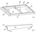
- the storage goods carriers are matched to the storage and output according to the invention and have a rigid border on three sides which extends beyond the usable area. On the delivery side there is no or no rigid border protruding beyond the usable area, if necessary an optional lowerable or tiltable border and at the same time or alternatively a bell-shaped threshold along the delivery side.
- An inclined usable surface in the storage goods carrier, which rises towards the delivery side, can also help to ensure that the stored goods do not protrude beyond the delivery side during transport but remain within the storage goods carrier.
- the storage area is equipped with systems that, from supported automatic processes, to a secured, registered, guided and controlled storage. This includes at least one control console, the for input by the operating personnel and information output to this is predestined.
- the storage opening is automatic with a controlled, essentially vertically mobile security stop equipped during or after a storage goods carrier is pushed out from the storage and retrieval machine in the storage opening and before the storage of goods along the borderless
- the delivery side of the goods carrier is temporarily positioned and in front of the Takeover of the storage goods carrier by the storage and retrieval machine from the storage opening is moved away again for storage in a shelf area.
- the function of the Safety attack is to ensure that goods are loaded come to rest within the storage goods carrier and not over the borderless one Protruding delivery side.
- a system also belongs to the storage opening Registration of machine-readable goods codes.
- the automatic dispenser according to the invention does not require a specific goods code entry system.
- Optical are conceivable Systems such as barcodes and barcode scanners, or non-optical Systems such as radio frequency identification systems.
- the collection of data serves another system that identifies the positions of effectively inserted partitions Storage goods carriers and thus the respective subdivision of a storage goods carrier into Storage bin columns, i.e. the positions and widths of storage bin columns registered.
- Various systems are also conceivable for this detection.
- Height detection system for height-oriented storage, how high the stored goods carrier is loaded. The recorded data are saved.
- the storage is specific to the functionality of the inventive Vending machines matched.
- the goods delivered should not be in the usual way predetermined and preprogrammed subjects, but as flexible and as possible can be stored in a space-efficient manner. And because storage bins are not for specific Goods are pre-programmed, but storage space depending on the respective Dimensions and quantities of the goods to be stored must be assigned With every storage process, the data is recorded, where which goods in which Quantity to be stored. Ultimately, this data is the prerequisite for the automatic outsourcing. This is only possible if the storage is on a systematic and, if possible, managed by the control system or the computer controlled process, which supports correct storage and if possible ensures. The operator guidance takes place via the control console.
- the automatic dispenser should be suitable for bulk and piece goods. These goods have different properties. Bulk goods with the same article number have the same properties and are packaged identically, at least over longer periods. General cargo has individual characteristics. Not only are they addressed, they can be uniquely packaged. But there are also piece goods that are sent to the recipient in standardized containers, packs or containers. In principle, it is thus possible to preferably pre-collect data from the bulk goods and piece goods with coded standard packs centrally and to save them in advance via a network on the storage device of the automatic dispenser.
- the pre-recording of data relating to the width of a storage bin column or the partition wall plug-in position is relevant if the storage is to function in such a way that the control device specifies to the operating personnel for goods, the dimensions and target orientation of which are previously known and pre-recorded in the storage bin columns the position of the partition.
- the storage goods carrier determined by the machine control or ordered by the operating personnel is fetched by the automatic storage and retrieval machine in the respective rack position and transported to the storage opening in the storage area. Because, in contrast to EP 0553470, customers or recipients do not have access to the storage goods carriers due to the automatic outsourcing and output described later and flexible and efficient use of the storage space is to be realized, the storage goods carrier according to the invention is basically designed to accommodate as many ordering units as allow the spatial conditions. In terms of information technology, it is no longer sufficient to save a specific subject and the stored order unit together. Instead, data must provide information on how a storage goods carrier is currently divided into storage bin columns and in which storage bin column which goods are stored and in what quantity.
- the goods In order to solve this problem in a work-efficient manner, the goods must be brought onto the storage goods carriers in a systematic manner. Depending on the preprogramming or setting of the machine, from the perspective of the storage area on the left or right side of the storage goods carrier, the storage of the goods begins in the storage opening. In the following it is assumed that storage on an empty storage item carrier always begins on the left side.
- coded standard packaging can be specified by the machine computer, the partition wall position and if goods with and without pre-recorded dimensions and target alignment data are to be stored on a storage goods carrier, the bulk goods and the piece goods first be stored with the pre-recorded standard packaging on the relevant goods carrier.
- the partition walls are inserted depending on the dimensions of the goods to be stored and run like the storage bin columns in the direction of removal. As a result, it is possible to assign the goods to be stored, depending on their dimensions and orientation, to the required storage space column widths during the respective storage process. Bulk goods and piece goods with pre-recorded coded standard packaging must be stored in accordance with the specified orientation.
- the partition must be inserted in the plug position specified by the control. For piece goods that do not have a pre-recorded, coded standard pack, the control system can neither specify the alignment nor the partition position. The storage must therefore be carried out in such a way that the code can be recorded automatically during the removal.
- a storage goods carrier of an automatic dispenser according to the invention is preferably dimensioned in the unloading direction in such a way that storage bin columns are on the one hand sufficiently long for the longest or widest goods to be dispensed by the machine, depending on the orientation in the storage bin column, and on the other hand are kept as short as possible so that they are stored individually in storage bin columns Bulk goods potentially unusable storage column length is as short as possible.
- This criterion is also advantageous because, on the one hand, it corresponds to the goal of keeping the footprint of the dispensing machine according to the invention as small as possible and, on the other hand, there is more flexibility with regard to the dynamic and unpredictable range of goods mentioned in the task if the dispensing machine is relatively short for many few long storage bin columns is designed, because in coordination with the outsourcing according to the invention, single-column bulk goods columns or individual piece goods have to be stored in storage bin columns, so that the automatic dispenser according to the invention is suitable for the storage of many different types of goods, whereby at most larger quantities of the same article can be stored in several storage bin columns , The goods are stored in the storage bin in the storage bin without an additional storage container.
- the previous data of the previous subdivision will be deleted at the latest when the first code of newly stored goods is entered or any partition wall positions have to be adjusted compared to the previous subdivision.
- the first item recorded with the goods code entry system during the considered storage process is automatically assigned to the storage bin column on the left and saved accordingly. If it is a bulk good or a piece good with a pre-recorded coded standard pack, the control device recognizes what kind of an article or what a standard pack it is, with what orientation the article or the articles are to be stored in the storage bin column .
- the relevant information on bulk goods and piece goods with pre-recorded, coded standard packs is stored on the one hand before starting the dispensing machine and on the other hand before assortment or standard adjustments, preferably from a control center in the machine controls and is stored on the control console after the goods have been recorded to support the operating personnel displayed.
- the partition wall position can also be specified via the control console.
- the storage opening along the storage side could be provided with markings (for example letters or numbers) in order to identify the position in question more quickly.
- LEDs or lamps in the insert opening along the insert side could indicate the plug-in position in which a partition is to be inserted. If, for example, three pieces of an article can be stored in a storage bin column, the second and third goods with the corresponding article code are also automatically assigned to the first storage bin column. When a fourth item with the same code is captured, this item is automatically assigned to the second storage bin column. At least one partition must then be placed on the corresponding storage goods carrier. If a different code is entered during storage, the control automatically closes the corresponding article and, because the storage bin columns must be sorted according to type, assigns it to the subsequent storage bin column and the associated data is displayed on the control console.
- the storage command can be issued via the control panel.
- This can be implemented in various embodiments.
- Either the registration system has a registration system at each potential plug-in position or the registration system consists of a registration system which can be moved linearly along the storage side of the storage goods carrier.
- each storage-side partition end is also equipped with a counterpart corresponding to the respective registration system.
- the automatic dispenser according to the invention can be equipped with a wide variety of relevant detection systems. Electrical, magnetic, mechanical or optical variants are conceivable.
- the detection system could consist of a divided contact point with an interrupted circuit at each potential partition plug position.
- the counterpart of the contact point on the partition forms a bridge and closes the circuit.
- the detection system consists of a contact point which can be moved linearly along the storage side of the storage goods carrier and also has an interrupted circuit. Every potential plug position is then passed with the contact point. Here, too, the circuit is closed where there are effectively partitions.
- the plug-in positions of the effectively inserted partitions can be determined from the closed electrical circuits.
- the detected partition positions can then be compared with the standard plug-in positions of the control system for bulk goods and piece goods with pre-recorded, coded standard packaging.
- storage space columns must not be less than a minimum width, so that the distances between the partition walls can also be checked to ensure that the minimum distance is maintained.
- the safety stop is moved away and the storage and retrieval unit pulls the storage goods carrier out of the storage opening.
- the height of the load is measured by sensors during the horizontal shift of the goods carrier onto the storage and retrieval machine.
- the storage of the goods carrier in a shelf position can then be accomplished in a height-oriented manner, ie in a space-efficient manner by the storage and retrieval machine.
- Two simpler storage variants according to the invention are conceivable: It is possible that specifications are only made for the bulkhead plug positions for bulk goods. In this case, the bulk goods and then the piece goods are to be stored on a storage goods carrier.
- a vertical data management system could be combined with any storage variant: the goods code could be provided with a sales or collection date, which is also recorded with the code reader during storage. This could ensure that goods would no longer be outsourced and discharged after this data had expired, but would be removed from the machine by the operating personnel. If shelf sectors described in the section on the storage area were to be realized in one embodiment, it would make sense to configure the storage program in such a way that the assignment to a shelf sector is automatically based on the goods codes recorded during storage (if necessary with a code addition from which, for example, that the goods in question must be stored in the cooling area).
- the storage is thus secured (safety stop), guided (after entering a goods code, the operator console shows how many of these goods are to be stored in a storage bin column; for bulk goods and general cargo with pre-recorded, coded standard packaging, the orientation of the goods in the storage bin column is also specified , optional also the partition wall position.
- control panel could be used to specify what goods can be stored on the same storage goods carrier, if the code reader were to detect a goods code that did not belong to this goods category, the control would warn the operating personnel), controlled (the The goods combination just mentioned on a storage product carrier; the number of partitions and the minimum distance between the partitions; if the partition positions are specified (for bulk goods and piece goods with pre-recorded, coded standard packaging) also the effective item itions of the inserted partitions) registered (which storage goods carrier, storage goods subdivision into storage space columns, their positions and widths, which goods in which storage space column and in which quantity); for general cargo: the pick-up code; optional sales or pick-up date and transport and output speeds and shelf sector) and automated (safety stop, position of the inserted partition walls and width of the storage space columns, recording of the loading height, determination of the shelf position, optional of the shelf sector; transport from the shelf position into the storage opening and vice versa; Compliance with an optional transport and output speed, sales and collection data management).
- the automatic dispenser according to the invention offers further advantages.
- Both the storage of the goods and the manual variation of the storage goods subdivision into storage bin columns take place at the central storage openings, which makes work easier.
- the data adjustments associated with storage and storage space allocation and subdivision are also flexible and work-efficient. Because these data adjustments result from the address of the affected goods carrier in the storage area, the recording of the article codes and the automatic recording of the partition positions and the loading height.
- the automatic dispenser according to the invention has at least one Storage area equipped.
- the storage and retrieval area must be open different heights of the storage device and can be on different floors be arranged if the dispenser is in a building with several floors is integrated.
- the retrieval area is essentially at the level of the following Lock area arranged.
- a system for automatic outsourcing characterizes the swap area. This system is preferably in the lock area opposite shelf area integrated and adjacent to the conveyor shaft. For the storage and retrieval machine automatically transports the storage goods carrier at least one good to be removed from the shelf position to the removal position, the is located in the delivery area and in the conveyor shaft.
- the inventive Automatic outsourcing takes place by having at least one good to be outsourced an essentially horizontal extension movement from the corresponding Storage space column of the mobile storage goods carrier is pushed into the retrieval position.
- the system essentially consists of a linear unit in the retrieval area ejection device running in the direction of delivery transversely to the direction of delivery in Dependency of the position and width recorded during the storage process Storage location column from which at least one good has to be outsourced positioned.
- the dispenser according to the invention inter alia also for very If the goods are to be of different sizes, the removal area is preferably included a second, parallel to the first linear unit with a second Ejection device equipped. The two linear units and Ejection devices can be moved and moved independently but in a coordinated manner.
- the at least one pushed out of a storage bin column Well received, guided by guardrails in the lock area that are automatic and flexible based on the data stored in the partitioning positions during the storage process of the corresponding storage bin column and as extensions of the Partitions of the storage bin column from which they are outsourced work directly in the Sluice channel.
- the lock area is located next to the storage area. This also borders on the conveyor shaft and is at least partially integrated in the shelf area opposite the storage area.
- the lock area consists of a lock channel running in the unloading direction with a lock channel entrance on the conveyor shaft side, a lock channel exit on the user area side and lock channel side walls.
- the lock channel floor is preferably formed by a conveyor system which takes over the goods which have been removed from the storage bin columns by being pushed out and transports them into and through the lock channel.
- the lock channel exit is blocked by a lifting, mortising or sliding gate. This gate is only opened for the removal of goods to be dispensed.
- the lock channel also has a lock channel ceiling and a lock channel piston that blocks the lock channel when the lock channel exit gate is open.
- This arrangement corresponds to an embodiment of the goods lock according to EP 1192609.
- the lock channel piston is not only movable horizontally through the lock channel, but that it can also be moved vertically and essentially lifted out of the lock channel.
- the drive for the horizontal movement of the lock channel piston is located above the lock channel ceiling.
- the connecting elements between this drive and the sluice channel piston run through slots in the channel ceiling, which are arranged in the swap or pass-through direction, so that the sluice channel piston can be moved horizontally without the lock channel ceiling.
- a lifting and lowering mechanism with which the lock channel cover and the lock channel piston are connected, ensures the vertical movement of the lock channel piston and the lock channel cover. If the lock channel piston is essentially lowered onto the lock channel floor and closes the lock channel entrance and thus the lock channel ceiling closes the lock channel like a lid from above and the lock channel exit gate is closed, the lock channel becomes a lock chamber that is closed on all sides. As already mentioned, the lock area is adjacent to the retrieval position in the conveyor shaft. And the lock channel is at least partially integrated into a shelf area. This is to enable outsourced goods to get into the lock channel as quickly as possible for efficient delivery. The lock channel must therefore have a width between the lock channel side walls that goods from all storage bin columns of a storage goods carrier can get straight into the lock channel.
- the lock area is equipped with guardrails that can be positioned flexibly. These run parallel to the lock channel and therefore parallel to the swap and pass-through direction. And transversely to this course, they can be moved horizontally independently, but in a coordinated manner, so that the guardrails can be positioned according to the detected partition wall plug positions so that they form extensions of the partition wall pair of the storage bin column from the lock channel above the lock channel floor, from which goods are to be removed.
- An outsourced good or an outsourced column of goods are transported sideways to the lock channel exit.
- the lock channel piston can be lowered substantially in the area of the lock channel entrance. Initially, however, only up to approximately just above the two guardrails or higher than the upper edges of the partition walls or borders on the goods carrier. Then the sluice channel piston is accelerated against the direction of unloading and moved slightly over the storage goods carrier into the unloading position, so that any goods that have not been removed from the storage side come to rest within the storage goods carrier before being stored in a rack position. If this process, which is also called safety loading in the following, is completed, the lock channel piston is moved horizontally away from the conveyor shaft in the unloading direction.
- the guardrails are moved into the appropriate, as narrow as possible recesses in the two side sluice channel walls so that the cutouts are filled as flush as possible with the inside of the sluice channel walls and there are no risks of trapping.
- the lock channel entrance is blocked and at the same time the lock channel ceiling closes the channel upwards. The outsourced and infiltrated goods are thus in the closed lock channel chamber.
- the lock channel exit gate can be opened without the lock channel allowing the lock channel to act or penetrate into the protected interior of the automatic dispenser.
- the conveyor system in the lock channel floor is accelerated and the goods are transported through the channel.
- the lock channel piston follows behind and, with increasing discharge, reduces the lock channel chamber volume visible from the user area and finally pushes the goods through the opening in the lock channel exit gate to the transfer point.
- the lock channel piston In the maximum discharge position, the lock channel piston preferably protrudes slightly from the opening in the lock channel exit gate into the transfer point, so that discharged goods cannot hinder the subsequent closing of the front gate.
- the lock channel piston can be lifted out of the lock channel in order to release the lock channel for any goods to be outsourced as far as the lock channel exit gate and to move the lock channel piston back into the area of the lock channel entrance.
- a goods code entry system This records the type and quantity of goods pushed from a storage bin column into the lock area. If the registration system cannot read a code and there is a no-read case or the type or quantity of the goods recorded does not match the specifications of the control device, the whole lot is pushed back into the storage bin column. This is done by lowering the lock channel piston on the lock channel exit side over the guardrails and then moving it in the direction of the goods carrier.
- the shop window in combination with the rejection option and the re-storage mechanism is probably a decisive criterion.
- Another characteristic of the lock area according to the invention is the design of the lock channel exit gate.
- a shop window is required for the lock channel to function as a showcase. This is integrated by installing it in the lock channel exit gate.
- the gate thus preferably consists of a frame for installation. This frame must have a structure that gives strength, particularly from certain dimensions of the lock channel exit opening. This allows the frame profile to have a certain depth, which creates a larger horizontal distance between the lock channel exit and the transfer point. This does not matter if the lock channel exit gate is closed.
- the lock channel exit gate as a double frame.
- One is designed for the integration of the shop window, the other is a flush extension of the lock channel and includes the opening through which the lock channel piston pushes the goods out of the lock channel.
- the latter frame has longer legs in comparison to the former frame in the direction of door movement, so that a fixedly positioned stop can reach into the frame with the opening, against which the frame part with the shop window is moved when closing.
- the lock channel exit gate according to the invention has the advantage that regardless of the position of the frame part which blocks the lock channel exit, the gate canyon or the joints around and between the lock channel exit and the transfer point are essentially permanently covered by the stop or elements of the double frame.
- the stem gate variant is preferred, which provides the shop window in the lower frame and the opening in the upper frame. In this way, the gate is moved against a stop above the lock channel exit, which is further away for children.
- the advantage of this variant is that a safety sensor system, which monitors the closing of the lock channel exit gate against the stop, can be implemented at the immobile stop and better protected above the swap level.
- the automatic dispenser according to the invention consists of at least one user area.
- This is equipped with a user console, which preferably includes a touch-sensitive monitor (touchscreen) for user guidance and user input.
- the user console is also equipped with a receipt printer and at least one payment processing system.
- a system as described in DE 19939211 is also a possible component for the delivery of piece goods. At least some of the functions mentioned could also be from a mobile phone and the like. be done from.
- at least one transfer point is characteristic of the user area. Depending on the width, this can also include a conveyor system running transversely to the delivery direction, which transports goods to one side of the transfer point, preferably in the direction of the user console.
- a dispenser designed in this way has a number of advantages.
- Both the storage in the storage bin columns, the management of the goods in the storage bin columns (the management of goods that were not identifiable during the removal, i.e. no-read cases, goods rejected by users and goods with expired sales or pick-up dates) and also the variation in the subdivision of the storage space associated with the flexible storage space allocation takes place in the central storage areas.
- the storage space is subdivided in a work-efficient manner with each storage process by assigning the storage column area centrally in the storage area by inserting the partition walls depending on the dimensions of the goods to be stored and automatically assigning the storage column height when the storage goods carrier is stored on the shelf at a height.
- Data adjustments in connection with the variation of the subdivision of the storage goods carriers and the assignment of storage goods carriers to shelf positions are carried out automatically during the respective storage process. Compared to previously known automatic dispensers, this represents a significant simplification, since with these it is not possible to vary the storage space subdivision during the respective storage process, but rather requires structural modifications and manual data adjustments. Due to the splitting of the total storage volume into two shelves, which can be served by a single feeder device and due to the flexible and work-efficient allocation of storage space volume during the respective storage process depending on the dimensions of the goods to be stored, many and very differently dimensioned compartments can be used with relatively short transport routes Direct access, that is, from which the delivery system can eject goods to be outsourced without reallocation.
- the system is designed as an automatic dispenser for assortments of potentially strongly, frequently and quickly varying assortments of potentially very different, in particular very differently sized bulk goods, and therefore especially predestined for the unpredictable flow of piece goods.
- automatic outsourcing and delivery and the associated spatial separation of outsourcing and transfer users do not have to remove goods manually from the compartments and they have no access to them, so that not only an order unit in a compartment or here in a storage bin column, but bulk goods are sorted by type can only be stored due to the space available.
- the storage goods carriers are designed for the storage of several order units, the storage is more efficient because the order units do not have to be stored in a separate compartment.
- Output is also more efficient because, under certain conditions, several bulk goods can be delivered in one retrieval and discharge cycle.
- the flexibility of the automatic dispenser according to the invention enables storage space to be subdivided and used depending on the development of demand. Frequently and less frequently converted goods can be allocated more efficiently, so that with the storage, which is coordinated with the delivery rhythm, it is better to strive to provide stocks per bulk goods that are practically used up on the next delivery.
- the suitability of the dispenser according to the invention for a wider range of articles and at the same time for piece goods implies more universal application possibilities and the potential to create more benefits for users. The more that can be done, the greater the synergy effects and the more attractive the dispenser appears and the more users will visit the device. The trend can increasingly be observed that conventional bank branches and post offices are closed and new ones opened in shopping centers, or at least enriched with ATMs.
- the invention described in WO 9425942 requires that in addition to the lift system, the ejection system is also vertically mobile and can be moved to the compartments.
- the automatic dispenser according to the invention ensures that the goods are not only dispensed automatically, i.e. without a time limit and without personnel, but that delivery can take place through a central opening thanks to the separation of outsourcing and takeover and that the delivery is also controlled.
- goods are electronically recorded when they are introduced into the lock channel in order to be able to control the type of article and the delivery quantity and optionally sales data and until then, despite the partially automatic control of data recorded during the storage, they may reveal undetected errors in the storage.
- the lock channel serves as a shop window box: through the lock channel exit gate equipped with a shop window, customers or recipients can visually check the goods before delivery and use the rejection option if necessary. This is the best way for the customer or recipient to react immediately in the event of obvious defects and to avoid tedious activities. Re-storage is possible because the goods are continuously guided by the guardrails during the removal, insertion and re-storage.
- the lock mechanism ensures that goods are automatically and safely removed and that the customer or recipient at the transfer point can conveniently take over the goods without having to concentrate, for example, on the handling of a gate or a flap. The goods are taken over at a comfortable height and without having to reach into unsanitary containers.
- the one presented here Lock mechanism a larger discharge capacity: Because of the Lock channel piston raised and moved back over the lock channel, can be outsourced in a subsequent cycle and in the Lock channel can be transported as soon as the lock channel piston is just as high Lifted over the lock channel floor is the guardrail for the next one Outsourcing could be positioned.
- the lock is also advantageous because it can perform several functions: In addition to the removal process, which ensures a high resistance to impacts and penetration into the interior, the lock channel also serves as a showcase and the lock channel piston ensures that goods not to be removed of the storage are within the storage bin column and that goods can be automatically re-stored in the storage bin columns if necessary from the lock channel. An additional infrastructure for automatic re-storage and a separate storage area are not required.
- the automatic dispenser according to the invention is also advantageous for the operator.
- the storage processes are work-efficient, because they can be conveniently carried out at central storage locations and per storage cycle of the feeder device, in which a storage goods carrier is stored in the storage area, depending on the goods dimensions, several goods can be stored at the same time. If, for example, an article of the range is delivered in larger and thus modified packages, it is sufficient to have it provided with a new article number and this together with other storage data (e.g. dimensions, orientation, number per storage bin column, specification, image and price) from Store the headquarters of the operating company from a decentralized location in the machine control system. The goods can then be stored using the usual procedure. Manual adjustments are not necessary in the storage area, retrieval area, lock area and user area.
- the mobile storage goods carriers with relatively short storage space columns are also advantageous for the service personnel when handling cases of automatic re-storage.
- the machine control saves these cases together with the affected storage bin columns so that the corresponding storage goods carriers can be ordered for the storage area.
- the number of goods to be checked in a storage bin column is very limited and easy to see. Rejected goods, no-read cases or goods with expired sales or pick-up dates can then be easily recognized and appropriate measures can be implemented easily.
- the dispenser according to the invention also has maintenance advantages. Essential technical systems are concentrated in specific areas. There is only simple standard technology in the periphery.
- the automatic dispenser according to the invention could make it possible to implement a new type of shop concept, for example for consumer electronics retail. While in the shopping street, where the real estate and rental prices are usually very expensive, only one exhibition venue with the advisory staff and exhibition equipment (TV, video recorder, etc.) would be run, the sales warehouse could be outsourced and in a dispenser according to the invention designed as a drive-in in a parking area or integrated into a parking garage. Customers could therefore concentrate fully on the shopping street and would be freed from the laborious hauling of goods and driving a shopping cart. The takeover of the goods could be postponed until after the stroll through the shopping street.
- the dispenser according to the invention could also provide particular benefits by offering hygiene articles.
- the automatic dispenser according to the invention is used for the dispensing of bulk goods and piece goods and, in addition, ATM functions are integrated into the customer or user console, an automatic center for one-stop handling can be implemented.
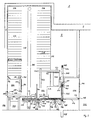
- a dispenser 1 in one possible embodiment: as a free-standing, immobile system with a building structure 2. It is just as well conceivable to integrate the dispenser into an existing building or as part of a new building (for example a parking garage) schedule. Mobile variants and smaller formats are also possible, as is the case with conventional vending machines with corresponding dimensions.
- the automatic dispenser according to the invention is equipped with a control device and connected to a storage device or equipped with a storage device. The embodiment illustrated in FIG.
- 1 has, apart from only a single user console 503, which is located between two transfer points 505 and 506, two "elementary" dispensers according to the invention (in the narrower sense) namely 3 (consisting of 101, 201, 301, 401, 501 and 505) and 4 (consisting of 102, 202, 302, 402, 502 and 506), which are integrated in terms of control technology and function in an automatic dispenser in the broader sense 1, on the one hand to increase the efficiency of the dispensing and to optimize the user benefit and on the other hand, to make storage more efficient.
- two "elementary" dispensers according to the invention in the narrower sense
- 3 consisting of 101, 201, 301, 401, 501 and 505
- 4 Consisting of 102, 202, 302, 402, 502 and 506
- the automatic dispenser 1 shown consists of two independent storage devices 201 and 202, each with its own storage and retrieval machines 209 (not visible) or 210, storage 101 or 102, storage 301 or 302, lock areas 401 or 402 and transfer points Have 505 or 506.
- the storage and retrieval machines 209, 210 can only be moved vertically in the y-axis of the conveyor shafts 207 and 208, respectively.
- the walls 2 and the lockable gate 5 separate the area 6 which is accessible to third parties from the area 7 which is only accessible to authorized personnel. Through gate 5, authorized personnel have access for service work, delivery and storage.
- the free spaces in the range of 7 or 100 can be used on the one hand for systems (not shown) (such as control device, storage device, UPS, etc.) and on the other hand serve for the provision, possibly also the intermediate storage of the goods before being stored in the automatic storage devices 201 and 202
- area 7 or 100 can be divided into different lockable sub-areas. This option could be important if different delivery organizations have possibly limited access through Gate 5. For example, bulk and general cargo could be delivered separately and temporarily stored.
- goods are brought onto mobile storage goods carriers 212, which are then automatically taken from the storage openings (103 and 104, cf. FIG. 2) by the storage and retrieval machines 209 and 210 and in rack positions (218, cf. 2) can be stored in the shelf areas 203 and 205 or 204 and 206 of the storage devices 201 or 202.
- the storage and retrieval device 209 in the storage device 201 is not in the drawn section of the conveyor shaft 207, which is formed by the two opposite shelf areas 203 and 205.
- the storage and retrieval unit 210 can be seen in the storage device 202.
- the goods carrier 212 which is in the unloading position in the conveyor shaft 208 in FIG. 1, lies thereon.
- Both retrieval areas 301 and 302 each have their own retrieval positions and ejection devices for the retrieval. These are integrated in the shelf areas 203 and 204, respectively.
- the lock areas 401 and 402 follow on the side of the conveyor shafts 207, 208 opposite the storage areas, at least partially integrated into the shelf areas 205 and 206.
- the storage area and lock area form the intermediate position which can be reached by the storage and retrieval unit.
- the transfer areas 505 and 506, which are located in the user areas 501 and 502 follow the lock areas.
- the interface between the lock area and the transfer point is formed by the lock channel exit gate 461 and 462, which can be moved vertically in the present embodiment.
- the transfer points 505 and 506 are freely accessible to third parties.
- the systems of the swap areas 301 and 302 essentially consist of preferably two independently driven linear units 303 and 305 or 304 and 306 running transversely to the swap direction. On each of them there is a positioning slide driven by the respective linear unit, each with one in Delivery direction and essentially horizontally extending ejection device 307 and 309 or 308 and 310 is equipped, which is provided with an ejection element 311 and 313 or 312 and 314 and in each case an independent drive for pushing ordered goods out of the stored goods carrier.
- the ejection devices must have a range that extends essentially to the delivery side 214 of a storage goods carrier 212 in the delivery position. At least one ejection device is positioned during the retrieval process.
- the positioning of the at least one ejection device in the storage goods carrier in the storage position in front of the storage bin column with the at least one item to be dispensed is controlled by the control device, the data being stored during the storage process by dividing the storage goods carrier into at least one storage bin column and being recorded by the system 109, 110 , be used.
- the lock areas 401 and 402 are at least partially integrated into the shelf areas 205 and 206 of the storage devices 201 and 202, respectively. These consist of a lock channel, among other things.
- the lock channel floor is essentially formed by a conveyor system 403 or 404, preferably a conveyor belt, which forms the delivery level, which in vertical positioning is matched to the delivery side 214 of the goods carrier 212 without a border or side wall in the delivery position.
- the conveyor system 403, 404 accepts goods 252 and 254 which have been removed from storage bin columns and transports them into the lock channel and through this to the lock channel exit gate 461 or 462 and, if necessary, in the opposite direction in the case of automatic re-storage.
- Upstream of the conveyor systems 403 and 404 are non-driven conveyor rollers 405 and 406, the meaning of which is explained in the section relating to FIG. 2.
- each lock area is equipped with two independently driven but coordinated controlled guardrails 407 and 409 or 408 and 410 that can be moved horizontally and transversely to the direction of delivery.
- the guardrails are connected to drive mechanisms beneath the conveyor belts 403 or 404 via guide rods which run through a joint 411 or 412 before the start of the conveyor belt 403 or 404, or through a joint 413 or 414 with an interrupted conveyor belt in the lock channel floor ,
- the guardrails are automatically positioned on the storage bin column from which storage is to take place, based on the data fixed during the storage process by dividing the storage goods carrier into at least one storage bin column and recorded by the system 109, 110.
- the storage bin columns are formed by partitions 242, 244 and 246.
- the crash barriers 408 and 410 form extensions of the partitions 244 and 246, which form the storage bin column from which they are relocated.
- each lock area has two lock channel side walls 415 and 417 or 416 and 418. These are provided with cutouts so that the guardrails can be moved laterally out of the lock channel.
- the recesses should be matched as precisely as possible to the outline of the guardrails and the guide rods in order to avoid the risk of getting caught. If the guardrails are in the recesses, as shown in Fig.
- the lock channel is released for a further element of the lock area: the lock channel piston 419 which is only visible in the lock area 401 (the lock channel piston 420 lies above the in the phase shown drawn section).
- the lock channel piston can be moved substantially horizontally along the axis of the swap direction and vertically. Coupled to this vertical movement are the lock channel ceilings 421 and 422 (not visible in FIG. 1).
- the lock channel exit gates 461 and 462, which are already mentioned, are also characteristic of the lock area and preferably each consist of a double frame according to the invention, the one frame in an advantageous manner Further training includes the shop window and the other the opening for the discharge (see FIG. 2).
- the lock channel exit gates each have an independent drive.
- the lock area preferably comprises a goods code reading or detection system (for example bar code scanner or other optical or non-optical systems such as radio frequency identification RFID) 423 and 425 or 424 and 426, which essentially looks at the beginning of the lock area 401 or 402 or at the lock channel entrance and at least one storage bin column length from the lock channel exit gate.
- This system has the function of recording and controlling the quantity and type of goods that have been outsourced, so that information technology creates the conditions that the user only receives goods that have actually been ordered and that he is only charged for goods that have actually been delivered.
- the user area 500 consists of a user console 503.
- Two transfer points 505 and 506 are assigned to this, so that the goods can be handed out to a customer with two independent locks and faster order processing and thus more user-friendliness can be achieved.
- the user console is centrally located between the two transfer points. In this way, the user has a better overview and, while picking up goods at the two transfer points, is always as close as possible to the user console 503 in order to get information from the user guidance as quickly as possible and to be able to react to input options and requests.
- the alternatives are available as for other dispensing machines.
- a compilation for vending machines can be found, for example, in document WO 01/91071 and for vending machines for bulk goods, in document DE 19939211.
- the user console or the man-machine interface in the automatic dispenser according to the invention is equipped with a touchscreen, so that for better clarity the display can always be focused on the current decision options and input prompts.
- a noteworthy difference between the user console of the automatic dispenser according to the invention and the above-mentioned fonts results from the options offered to the user in an advantageous further development, which result from the shop window and the rejection option and require adequate user guidance. More on how it works follows in the presentation of the discharge process. Regarding the structure of the transfer points, the following elements can be pointed out here: 507 and 508 are stops and 509 and 511 or 510 and 512 are light barriers for controlling the removal of goods.
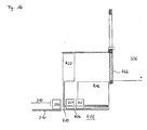
- FIG. 2 shows a side view of the section AA marked in FIG. 1 through the storage 102, storage 202, storage 302, lock 402 and user area 502 of the embodiment of an automatic dispenser 1 according to the invention shown in FIG. 1 (in the broader sense) or 4 (in the strict sense).
- the machine casing is formed by walls 2.
- the user area 500 or 502 can be protected against the weather with a canopy 8.
- the storage area 102 includes the storage opening 104 integrated in the shelf area 204 with the control console 106 for the personnel and the storage level or position 108, onto which the storage goods carriers 212 can be pushed by the storage and retrieval device 210 for the storage process (or more comprehensively: for management) , 110 symbolizes a system for the automatic detection of the positions of the effectively inserted partition walls 246 with the detection system 112. The mode of operation will be explained later in connection with FIG. 9. Furthermore, the storage area is equipped with a device to facilitate the storage of the goods on the storage goods carriers.
- a guide mechanism 114 running on both sides of the storage opening 104 around two deflection wheels 116 and 118 and along the vertical interface to the conveyor shaft 208 advantageously moves a safety stop 120, which is designed as a roller and runs transversely through the storage opening 104 and parallel to the delivery side 214 of the goods carrier in the storage position the pushing out of a storage goods carrier into the storage opening 104 automatically into the area of the deflection roller 118, so that the safety stop during the storage along the border or side wallless delivery side 214 of the storage goods carrier in the storage position prevents the goods from being pushed in too far.
- the safety stop 120 is automatically moved by the guide mechanism 114 over the highest potentially goods that can be stored, essentially to the deflection roller 116, in order to enable the goods carrier to be moved from the storage position into the conveyor shaft onto the storage and retrieval unit at best.
- the sensor system 122 detects the loading height on the goods carrier so that a space-efficient, height-oriented storage can then take place.
- the storage takes place in that the storage and retrieval machine 210 transports the storage goods carriers taken over from the storage opening 104, driven by 262 through the conveyor shaft 208 to a free shelf position 218 in one of the shelf areas 204 or 206 of the automatic high-bay warehouse 202 and then pushes them out again.
- the storage and retrieval unit 210 transports a storage goods carrier with at least one item to be retrieved into the retrieval position shown in FIG. 2 between the retrieval area 302 and the lock area 402.
- the automatic retrieval is carried out by the systems in the retrieval area 302.
- the linear units 304 and 306 can do this Ejection devices 308 and 310 are moved into the position behind the storage bin column with the goods to be removed or the goods to be removed.
- the ejection takes place with one or two ejection devices, so that one or two ejection devices are positioned accordingly.
- the goods become or become the goods from the storage goods carrier pushed into storage position.
- the ejection devices for example formed by telescopic axes, are provided with an ejection element 314.
- the ejection devices 307 to 310 are preferably connected to both linear units 303 and 305 or 304 and 306: for example 310 to the slide driven by linear unit 304 and to a non-driven slide on linear unit 306 in order to achieve a better guide position.
- the non-driven conveyor roller 406 is adjacent to the discharge positions.
- Two wipers 428 and 430 then follow, which the joint 412 (cf. FIG. 1) form.
- the subsequent conveyor system 404 takes over the outsourced goods and transports them into and through the lock channel, which is formed, among other things, by the lock channel side walls 416, 418.
- the drive system is connected to the conveyor system 404 by the conveyor system 436, which transports the goods to the stripper 438, which adjoins the lock channel exit gate 462.
- the guide rods 440, 442, 444, 446 run through the joints 412 and 414.
- the guide rods 444 and 446 connect the guardrail 410 to the drive mechanism 450 and guardrail 408 is connected to the drive mechanism 448 via the guide rods 440 and 442.
- the linkage is better guided and protected than in the case of a realization adjacent to the conveyor shaft 208 between the retrieval position and the lock area.
- the goods code reading and recording system is symbolized by 424.
- 416 is a lock channel side wall
- 422 is the vertically movable lock channel ceiling. The ceiling 422 is moved together with the lock channel piston 420 with the vertical drive mechanisms 452 and 454 (located on the cut off, opposite lock channel side).
- the lock channel piston can also be moved horizontally by the drive mechanism 456 in the swap direction.
- the lock channel piston is located above the lock channel so that the goods 252 and 254 to be dispensed (potentially of course also 256; this cannot be seen from the drawing) can get into the lock channel.
- the lock channel essentially has a length in the discharge direction that enables the contents of an entire storage bin column to be taken up.
- the lock channel exit is closed by the lock channel exit gate in the process phase shown. In an advantageous development, this is designed as a lock channel exit double frame gate 462.
- the lower frame which encompasses the shop window 466, forms the mortise gate which, when closed, extends as far as the stop 460 or up to a rubber lip 470 equipped with a safety sensor.
- the shop window is inserted flush in the frame elements so that there is no risk of getting caught when moving the gate.
- the upper frame forms the opening 464, through which, when the opening 464 is lowered in such a way that the edge 468 comes to lie at the level of the lock channel floor 404 and the opening 464 forms an extension of the lock channel, the goods to be dispensed are discharged.
- the frame part which comprises the opening 464, lies almost completely above the stop 460 and on the inside of the machine casing 2, which is not accessible to the public, so that possibilities of pinching, penetrating and acting are avoided.
- the internal dimension of the vertical part of the upper frame is larger than that of the lower frame.
- the upper frame must essentially cover the distance between the upper edge 474 of the stop 460 and the upper limit of the lock channel 472, so that when the lock channel exit gate 462 is in the lowered, open position, the frame part 476 essentially comes to rest at 474 and at the same time the frame part 468 forms a plane with the lock channel floor 404. In this way, it is possible to let stop 460 protrude into opening 464 or to implement it within the travel range of the upper frame of lock channel exit gate 462, to move opening 464 above the lock channel exit behind outer shell 2 and at the same time move the gate canyon upwards in the area of the gate opening 464 permanently locked with 460 stop.
- the double frame construction it is also achieved that from the publicly accessible area only a section of the movement path or the gorge of the lock channel exit gate is visible, the side joints of which are essentially filled in by the double frame at all times, while the movement space downwards either permanently through the shop window part or at least is blocked by the lower frame boundary 468 of the door opening 464 and prevents cavities accessible against the stop 460 above.
- the stop 460 is excellently suited for the installation of the security sensor 470, which is located above the flow of goods and is therefore protected, and monitors the closing of the lock channel exit gate 462.
- a recess 478 may be required, which is used to lower the lock channel exit double frame gate sufficiently so that the frame boundary 468 of the gate opening 464 comes to lie at the same height as the lock channel floor and the goods are guided to level 514 in the transfer point 506 can be pushed.
- Stop 508 physically stops goods
- light barrier 510 monitors the transfer point 506 by sensors to stop the transfer if the light barrier is interrupted.
- 503 in turn represents the user console. The users can take over the goods from the transfer point 506.
- FIG. 3 shows an axonometric representation of a storage goods carrier 212 which is matched to the storage, storage and retrieval system according to the invention.
- This has on three sides a rigid border or side walls 217 or 219 which exceeds the usable area 220, while none or at most along the delivery side 214 a lowerable or foldable border or side wall is conceivable.
- the delivery side is drawn without a flexible border.
- the usable area 220 runs from the storage 216 to the delivery 214 slightly rising. Additionally or alternatively, it is conceivable to integrate sleepers into the usable areas along the borderless delivery sides 214 of the goods carriers. Because goods to be delivered have to pass the threshold when they are pushed out, this threshold must not exceed a certain height.
- a bell-shaped design of the threshold should be advantageous.
- bulk goods are stored individually in single columns and piece goods individually in storage bin columns.
- the storage bin columns are formed by flexibly pluggable partition walls.
- a partition 240 is inserted into the storage goods carrier 212 shown in FIG. 3.
- the coordination of the outsourcing process requires that goods to be outsourced can be pushed out of the storage bin columns.
- the storage bin columns must therefore run in the unloading direction.
- the storage goods carriers have plug-in positions 222 arranged in a grid.
- At least two holes 224 and 226 are used in the usable area 220 to insert partition walls, and a recess 228 in the border or side wall 217 along the insert side 216 is used on the one hand.
- Partition walls are designed for insertion into plug-in positions as identified by number 222. Why the plug-in positions 222 are distributed on one side over the usable area can be seen from the explanations for FIGS. 5 to 8.
- FIG. 4 An example of a partition 240 is shown in FIG. 4.
- the partition walls 240 are brought into plug positions 222, that the projection 234 comes to rest in a recess 228 and the pins 230, 232 into the associated plug holes 224, 226, i.e. 230 in 224 and 232 in 226.
- Number 236 on the face of the projection 234 marks one depending on the system for the automatic detection of the partition positions potentially necessary and with counterpart corresponding to the selected acquisition system 112. If that Detection principle works electrically, 236 would be an electrically conductive Contact point that bridges the interrupted contact point on counterpart 112.
- the dividing walls can be angled to match Have lower edge so that the upper edge of the in a plug position 222 inserted partition runs horizontally.
- the method for storing goods in the automatic dispensers according to the invention is described and shown how the goods can be allocated storage space columns in a flexible, space and labor-efficient manner depending on the respective goods dimensions. 5 to 8, which represent individual phases of the storage method according to the invention.
- the one with the specification of the partition plug position for bulk goods and piece goods with pre-recorded, machine-readable coded standard packaging is to be presented.
- the delivered goods are stored in the automatic storage devices 201 and 202 at the storage areas 101 and 102. Because the procedure is identical in both cases, a storage in 202 is assumed for simplification.
- the personnel orders an empty storage goods carrier 212 via the operating console 106 (cf. FIGS. 2 and 9).
- the storage and retrieval device 210 fetches the storage goods carrier determined by the control from the corresponding shelf position 218 in one of the shelf areas 204 or 206 of the compact high-bay warehouse and transports the storage goods carrier through the conveyor shaft and pushes it into the storage opening 104 onto the storage level 108.
- the safety mechanism 120 is automatically moved from the rest position by the deflection roller by the drive mechanism 114 116 to the position shown in FIGS. 5 to 9 at the lower deflection roller 118, so that the goods come to lie within the storage goods carrier already during storage and do not protrude too close to the delivery side 214 or even beyond.
- FIG. 5 to 8 show the top view of a storage goods carrier 212 in the storage level 108 and the lowered safety stop 120.
- the stored goods carrier is empty. If necessary, partition walls that were still present after being pushed out by the storage and retrieval unit and were not inserted appropriately for the goods to be stored have been removed.
- Storage can begin. In order to automate and thus simplify the recording of the storage location data and to optimize the options for operator guidance and control by the control device, the storage takes place in a systematic manner. From the point of view of the personnel in the storage area 102, which is adjacent to the storage side 216, storage is always started on the same or predefined or programmed side 219 of the storage goods carrier and then stored to the other side. As before, it is still assumed that it would start on the left.
- an automatic dispenser according to the invention can also be implemented in such a way that the first plug-in position is at the specified distance from the right border side and is always started on the right side during storage). Due to this requirement, the plug positions of the storage goods carriers are not evenly distributed. Again from the point of view of the operating personnel in the storage area 102, the first plug-in position (in FIG. 3 the plug-in position 222) is at a distance from the left-hand border 219 which is just sufficient to accommodate the goods to be dispensed by the automatic dispenser with the narrowest storage space column requirement to be able to store easily but well managed. All other plug positions up to the right side border are then arranged in a grid-like manner at equal intervals.
- the goods with pre-recorded data i.e. bulk goods and general cargo with pre-recorded, machine-readable, coded standard packaging
- Bulk goods and piece goods with pre-recorded, coded standard packaging are to be brought in the specified orientation in storage bin columns, whereby the bulk goods are to be stored in single columns while the piece goods are to be stored individually in storage bin columns.
- the storage bin columns are always filled first, before new ones are started. The code of every stored good and thus the stored quantity is recorded in a systematic way with a registration system.
- the associated data (alignment in a storage bin column, number of bulk goods in a storage bin column, plug position for the subsequent partition) are displayed on the operating console 106.
- the partition must be inserted in the plug position specified by the control device.
- General cargo without a pre-recorded, coded standard pack is individually stored in storage bin columns.
- the control device cannot specify the orientation or the partition wall insertion position.
- the storage must therefore be carried out in such a way that the code can be recorded automatically during the removal.
- the partition is to be inserted in such a way that the general cargo lies loosely but well guided in the storage space column to be formed.
- the storage may only be carried out if only bulk goods without a pre-recorded, coded standard pack are to be stored on this goods carrier, otherwise the partition plug positions can no longer be specified and checked.
- the partition plug positions can no longer be specified and checked.
- the alignment must take place in such a way that the code can be read during the automatic retrieval and the partition 248 must be positioned in such a way that the stored goods are loosely but well guided, so that friction during the automatic retrieval is unlikely , It is to be brought individually into the storage bin column 271 as piece goods.
- two processes are started. On the one hand, the safety stop 120 is accelerated around the deflection roller 118 in the direction of the stored goods, so that the stored goods come to lie in the storage bin columns at a safe distance from the delivery side 214 before being stored. Then the safety stop 120 is moved to the deflection roller 116.
- the system 110 is activated for automatic detection of the actual partition plug positions.
- the detection takes place by decentrally activating a detection system at each plug position 222 or by driving a detection system 112 driven by a linear unit past each plug position 222.
- a circuit interrupted at contact point 112 is energized.
- the circuit is closed by the contact bridge 236 (cf. also FIG. 4).
- Each partition therefore generates a signal that indicates where the partition was actually inserted.
- the actual positions are then compared with the target positions.
- the storage command is not executed. Instead, the deviations are displayed to the staff via the man-machine interface or the control console and optional acoustic or optical signals so that the necessary corrections can be made.
- the method with system 110 enables the automatic detection and storage of the partition positions and thus the corresponding storage bin column positions and widths. However, a check is not possible. As soon as the process of system 110 has been correctly completed after any corrections, the storage command is continued and the storage goods carrier is moved onto the storage and retrieval unit.
- the loading height measuring device 122 automatically detects the height of the goods stored on this storage goods carrier so that it can be stored in a free shelf position 218 in the storage device 202 in a height-oriented manner, ie using the storage space efficiently.
- Storage space is allocated flexibly with each storage process depending on the dimensions of the goods.
- the storage space column subdivision is varied by simply repositioning the partition walls. Both this variation and the storage of the goods themselves take place in the central storage areas.
- the height-oriented storage takes place automatically and ensures space-efficient use of the storage room height. Goods can be freely stored in the context of the storage method according to the invention, because the articles are not preprogrammed to a specific compartment. With the help of systematic storage, the effort for the collection of data, where which articles are stored, can be reduced to a minimum.
- the automatic data acquisition during storage enables a certain control and ensures compliance with the storage process.
- FIG. 9 shows a side view of a storage method according to the invention coordinated storage opening 104 of the storage area 102 in the situation of FIG. 8.
- Storage goods carrier 212 is in the storage position on storage level 108 in the storage opening 104.
- the safety stop 120 is located at the Deflection roller 118 along the borderless delivery side 214 of the goods carrier 212.
- the system 110 for recording the Partition positions activated. If the recorded data with the specifications match, the safety stop 120 is driven by mechanism 114 moved to the deflection roller 116, so that the storage and retrieval unit the storage goods carrier can convey from the storage opening into the conveyor shaft.
- FIGS. 10 to 15 show individual phases of the automatic retrieval process and individual process steps and functions of the automatic lock, which is at least partially integrated in the storage area, and the interplay of retrieval and discharge.
- the automatic removal of goods from storage goods carriers according to the invention and loaded according to the invention requires that the control device has access to the storage device with the current data, which provide information as to which rack position which storage goods rack is stored in, how the different storage goods racks from partitions in how many and how wide storage bin columns are divided and in which storage bin column what goods are stored.
- the data For bulk goods, the data must also be stored on how many of a specific article are currently stored in a storage bin column. As already mentioned, the information about how many linear units of measurement in the dimension of the delivery direction the different articles require is also stored for the bulk goods. Finally, it is optionally also possible to save sales or collection dates. This makes it possible to block goods with an expired sales or collection date for automatic output. However, the cases in which outsourcing can be started are of interest.
- the storage and retrieval unit 210 transports one in the storage area Storage goods carrier 212 with goods to be removed 252 and 254 through the conveyor shaft 208 towards the swap position.
- the ejection device is located in the storage area 302 310 from the positioning mechanism to the ejection position at the storage bin column, in of the goods to be outsourced. If the Fig. 10 to 15 the 1 situation, the bin column has a width that a coordinated extension by both ejectors 308 and 310 is required. Thus, both are moved while the storage goods carrier is being transported to the unloading position Ejection devices in each one ejection position in one of the halves of the considered Storage bin column moved.
- the lock channel piston 420 is in one possible rest position adjacent to the inside of the shop window 466 and in Essentially on the conveyor belt 404.
- the guardrails 408 and 410 must therefore outside the lock channel in the side recesses of the side walls 416 or 418 of the lock channel. In the top view, these are those in FIG. 1 shown positions of 407 and 409. In the situation of FIG. 10 one can see only the guardrail 408 which lies in the recess of the side channel wall 416.
- the principle of the retrieval method according to the invention is to push the goods to be removed from central storage areas from mobile storage goods carriers, which can be divided into storage bin columns by flexibly inserting partition walls depending on the dimensions of the stored goods.
- the flexible subdivision means that storage bin columns can firstly be at different positions on the storage goods carrier and secondly that the storage bin columns can have different widths.
- the push-out or ejection system must therefore be able to outsource depending on the respective position and width of the storage bin column.
- the length dimension in the direction of retrieval of a storage bin column that is claimed by a good to be outsourced is additionally the number of actually in the storage bin column from which the goods have to be removed and that Number of goods to be removed from this storage bin column relevant.
- the discharge of bulk goods has to be done to such an extent that the goods to be removed from a storage bin column reach conveyor systems 403 and 404, while the goods not to be removed, here 256, remain in the storage bin. How many are to be outsourced results from the order quantity that the customer has entered at the customer console 503 or via a mobile input device such as a mobile phone.
- y stands for the ejection distance to be traveled for a specific removal
- m the maximum ejection distance, which is essentially in the rest position of the ejection element 311, 312, 313 and 314 (cf. position of 311 or 313 in FIG. 1 or position of 314 in 10) extends to the delivery side 214 of the goods carrier 212 in the delivery position.
- b is the number of goods actually present in the relevant storage bin column before the outsourcing considered
- x is the number of goods to be retrieved for the outlet under consideration
- I is the length dimension in the delivery direction of a storage bin column that is claimed by a good of a specific article. If a also represents the max.
- each retrieval area 301, 302 is preferably equipped as shown in FIG. 1: with two independently driven but coordinated positioning ejection devices, so that storage bin gaps that reach the stated width are available or exceed, is outsourced in that both ejection devices, as shown in FIG. 1 in the unloading area 302, eject the goods in a coordinated manner. While in the case of narrow storage space gaps that do not reach the stated width, a single ejection device is positioned essentially in the middle in front of the storage space column with the goods or goods to be removed, in the case of storage space gaps that reach or exceed the stated width, the ejection devices are each in one half the storage bin column is positioned.
- FIG. 11 shows the outsourcing process phase shown in FIGS. 1 and 2 with the storage and retrieval unit that has transported the goods carrier 212 into the retrieval position.
- the guardrails have now also moved into position. As can be seen from FIG. 1, guardrail 408 is therefore no longer visible in FIG. 11, but 410.
- the guardrails as extensions of the partitions 244 and 246, ensure that they are swapped out and inserted into the lock channel.
- the goods 252 and 254 to be outsourced according to the customer order have been pushed out of the storage space column onto the conveyor system 404 by the ejection devices 310 and 308, which takes over the goods and transports them between the guardrails 408 and 410 into the lock channel.
- the outsourced goods have passed the code entry system 424 or 426.
- the type and number of goods can be checked. If identification was not possible (no-read case), a discrepancy between the target and the actual (in terms of code or quantity) has occurred or a user uses the rejection option by entering the appropriate information in the user console 503, the automatic re-storage is started ,
- the conveyor system 404 is then moved in the opposite direction until the conveyor system has essentially covered the path from the shop window to the area of the light grid 484 or there are no more goods in the area of the light grid 484.
- the lock channel piston 420 can then be lowered in the area of the light grid 484. But not up to the conveyor belt but only up to the guard rails 408 and 410, so that the re-storage can also be carried out in a guided manner.
- the goods 252 and 254 are then driven by conveyor system 404 and in the final phase are transported or pushed from the lock channel piston 420 in the direction of and onto the goods carrier 212 back into the storage bin column.
- the storage and retrieval unit 210 can then re-store the storage goods carrier 212 in one of the shelf areas 204 or 206.
- the re-storage is stored in connection with the storage goods carrier and the goods concerned, so that the operating personnel can manage the case efficiently.
- the automatic output can be continued.
- the goods to be delivered 252 and 254 are from the conveyor system 404 transported into and through the lock channel.
- the ejectors 310 or 308 can go back to the storage area 301 in FIG. 10 or also in FIG. 1 shown position are retracted so that the ejection elements 312 and 314 are no longer in the area of the conveyor shaft 208.
- the Goods to be outsourced have passed through light grids 482, which can essentially be via the lock channel and on the lock channel entrance side of the outsourced Goods sluice lock piston 420 essentially in the range of Light curtain 482 in the position shown in Fig. 12 - for the time being not up to Conveyor system 404 but only lowered over the guard rails 408 and 410 become.
- the storage goods carrier 212 can be transported from the storage and retrieval unit into the storage area. If the guardrails 408 and 410 have also moved into the cutouts in the lock channel side walls 416 and 418, the lock channel piston 420 is essentially lowered onto the conveyor system 404 and the lock channel cover 422 closes the lock channel from above. And the lock channel piston 420 is moved towards the shop window until the lock channel entrance is also closed.
- the lock channel is now a closed lock channel chamber, which preferably has at least the length dimension of a storage bin column in the delivery direction, so that the contents of an entire storage bin column can be output in a discharge cycle when ordered accordingly.
- the lock channel exit gate 462 can only be opened, in the present exemplary embodiment it can be lowered when the lock channel entrance is closed by the lock channel piston 420.
- the opening takes place by lowering the lock channel double frame gate 462, the shop window 466 disappears below the level of the lock channel bottom and the frame part with the gate opening 464 is positioned in front of the lock channel exit, so that the side frame parts which surround the gate opening 464 and the frame surface 468, which lies at the level of the lock channel floor forms an extension of the lock channel and thus obscures the gorge in which the lock channel exit gate 462 is moved, which contributes to a better flow of goods and less pinching and impact risks.
- the two conveyor systems 404 and 436 can be started again in the delivery direction.
- the goods are thereby removed from the lock channel.
- the lock channel piston 420 follows the goods to be removed, thereby increasingly reducing the volume of the lock chamber and pushing the goods through the frame part with the gate opening 464 onto the level of the transfer point 514. If the lock channel piston 420 has reached the maximum ejection position shown in FIG. 15, this is achieved in the following step into the position shown in FIG. 10, as close as possible to the inside of the lock channel of the lock channel exit double frame gate 462. In this position, the lock channel piston continues to shut off the lock channel exit.
- the lock channel piston can be moved away from the lock channel exit and essentially lifted out of the lock channel in order, at most, to allow further goods to be discharged to be brought in to the shop window.
- At least the part of the sluice channel piston which projects out of the sluice channel through the opening 464 in the maximum ejection position has walls which avoid the risk of pinching between the sluice channel piston and the frame of the opening 464 or the sluice channel.
- the light barriers 509, 511 and 510, 512 have the function of controlling the discharge of the goods into the transfer point 505 or 506. If the light barrier is interrupted, the discharge is stopped until the light barriers are no longer interrupted.
- the automatic goods dispenser according to the invention as in the embodiment shown in FIG. 1, consists of two storage devices, each with a storage opening, a storage and lock area, and a transfer point, the automatic dispensing can be made more efficient if the same items are roughly half each in both storage devices be stored. Even if the customer orders a larger number of the same item, the dispensing can then take place more quickly and with the help of both dispensing machines. Finally, the dispenser according to the invention could be made even more attractive for customers or users if the transfer points were each equipped with a conveyor belt running transversely to the direction of delivery, which in each case transported the goods to the side of the transfer point which was adjacent to the customer or user console 503.
- FIG. 16 is a phase of automatic outsourcing and infiltration into a Lock with vertically movable lock channel floor shows.
- the lock channel ceiling can thus be fixed and the lock channel piston only has to be horizontally movable.
- FIG. 17 An alternative embodiment is shown in FIG. 17.
- the top view is shown to an automatic dispenser with a 280 rack operator.
- This additional direction of movement enables the storage goods carrier relative to Position the sluice area so that the storage bin column with the aligned at least one good to be outsourced to the channel side wall 418 can be. No guardrail is therefore required on this channel side.
- This Construction has the advantage that the lock channel is shorter than the delivery side of a storage goods carrier.
- the inventive method also works when the lock area from a rotary lock (described in European Patent Application No. 01 810 765.6) is formed.
- 18 shows a possible arrangement. Because the Lock channel can be rotated by means of a rotating body 497, can Showcase 466 in a fixed position. For user inspection the Gut 252 is only driven to the shop window. As soon as he has accepted the good the rotating body is turned to the transfer point. Before the horizontal movable lock piston 498 moves the material out of the lock area, the guardrail 408 is moved out of the lock channel.
- FIG. 19 is a plan view of a further embodiment in FIG Dispensing machines are shown with two storage areas, each from a circular warehouse each formed with a storage and retrieval unit (281, 282) which can be rotated about a vertical axis become.
- the swap area has an additional element: the Positioning slide 320 and 321, which is the positioning of the goods carrier enable with regard to the lock.
- the lock area is again one Rotary lock formed with rotating body 497. This can be goods from the retrieval area with the positioning slide 320 to take over as shown in the Transfer point 506 protected by the horizontally movable window gate 466 To be able to present users.
- the shop window gate 466 can be driven to the transfer point 505 and the lock channel piston can Move goods 252, 254 to transfer point 506.
- the discharge of the Goods 252 and 254 can be imported into goods 257. It would then preferably be good 257 presented at the issuing point 505 and after the Display window gate to the transfer point 506 to the transfer point 505 issued become.
- FIG. 20 is a detail of a side view of a section through the storage, Storage, retrieval, lock and user area of the embodiment according to FIG. 19 shown.
- FIG. 21 A simpler variant of the embodiment just discussed is shown in FIG. 21 shown.
- the positioning slide 320, 321 can be omitted if the Lock channel and the storage goods carriers have the same width. Because then the storage bin columns are no longer matched to the lock channel side wall every lock chamber must be in both Each of the lock channel side walls has a guardrail (408, 410).
- Ejection devices 311, 312, 313, 314, but also the lock chambers of the control device with the help of the storage process by dividing the Storage goods carrier fixed in at least one storage bin column and by system 109, 110 recorded data are brought into the retrieval position in such a way that the Lock channel side wall 417 the extension of the storage goods carrier side wall 219 forms. Only one guard rail is therefore required for each lock chamber).
- the elements 493, 494 ensure re-storage.
Landscapes
- Physics & Mathematics (AREA)
- General Physics & Mathematics (AREA)
- Warehouses Or Storage Devices (AREA)
Applications Claiming Priority (2)
| Application Number | Priority Date | Filing Date | Title |
|---|---|---|---|
| CH15712002 | 2002-09-13 | ||
| CH15712002 | 2002-09-13 |
Publications (1)
| Publication Number | Publication Date |
|---|---|
| EP1400932A1 true EP1400932A1 (fr) | 2004-03-24 |
Family
ID=31892701
Family Applications (1)
| Application Number | Title | Priority Date | Filing Date |
|---|---|---|---|
| EP03405674A Withdrawn EP1400932A1 (fr) | 2002-09-13 | 2003-09-12 | Procédé et dispositif de stockage et d'extraction automatique d'articles individuels |
Country Status (1)
| Country | Link |
|---|---|
| EP (1) | EP1400932A1 (fr) |
Cited By (17)
| Publication number | Priority date | Publication date | Assignee | Title |
|---|---|---|---|---|
| EP2876614A1 (fr) | 2013-11-25 | 2015-05-27 | Wincor Nixdorf International GmbH | Station de paquets entièrement automatique |
| WO2015197903A1 (fr) * | 2014-06-26 | 2015-12-30 | Benito Manuel Ortiz Padilla | Système automatisé pour garder des objets personnels |
| CN106326940A (zh) * | 2016-08-31 | 2017-01-11 | 广州御银自动柜员机科技有限公司 | 一种旋转仓储式发盒器 |
| CN107967751A (zh) * | 2017-12-19 | 2018-04-27 | 董鹏飞 | 一种售货机 |
| CN110148264A (zh) * | 2019-04-04 | 2019-08-20 | 平安科技(深圳)有限公司 | 一种储物柜的管理方法及设备 |
| CN110310438A (zh) * | 2019-06-18 | 2019-10-08 | 深圳怡丰机器人科技有限公司 | 一种智能存取系统 |
| CN111382969A (zh) * | 2018-12-30 | 2020-07-07 | 北京极智嘉科技有限公司 | 订单处理方法、装置、设备及存储介质 |
| CN112669098A (zh) * | 2020-12-18 | 2021-04-16 | 航天信息股份有限公司 | 一种税务UKey自助领取装置 |
| CN113012358A (zh) * | 2021-02-20 | 2021-06-22 | 四川观想科技股份有限公司 | 一种危险品仓储取存管理一体化系统 |
| US20210201617A1 (en) * | 2019-01-31 | 2021-07-01 | Yuyama Mfg. Co., Ltd. | Cassette handling apparatus and drug handling apparatus |
| CN113570654A (zh) * | 2021-06-16 | 2021-10-29 | 上海工程技术大学 | 基于最小外接矩形的汽车表面缝隙尺寸检测方法及其应用 |
| CN114604615A (zh) * | 2022-03-24 | 2022-06-10 | 广州金智为电气有限公司 | 一种一体化加工设备 |
| DE102021113020B3 (de) | 2021-05-19 | 2022-11-17 | Sar Elektronic Gmbh | Verkaufsvorrichtung |
| CN115670139A (zh) * | 2021-07-22 | 2023-02-03 | 深圳市华正联实业有限公司 | 一种存储柜 |
| CN115879864A (zh) * | 2022-12-15 | 2023-03-31 | 江苏中博通信有限公司 | 一种智慧无人仓储精准化管理方法及系统 |
| CN117197952A (zh) * | 2023-07-27 | 2023-12-08 | 长电新能有限责任公司 | 水电站检修指示牌智能收发柜及使用方法 |
| US12051038B2 (en) | 2018-12-30 | 2024-07-30 | Beijing Geekplus Technology Co., Ltd. | Order processing method, apparatus and device, and storage medium |
Citations (4)
| Publication number | Priority date | Publication date | Assignee | Title |
|---|---|---|---|---|
| US4814592A (en) * | 1986-05-29 | 1989-03-21 | Videomat Associates | Apparatus and method for storing and retrieving articles |
| EP0574732A1 (fr) * | 1992-06-18 | 1993-12-22 | Digitron AG | Magasin pour le stockage d'objets |
| US6029851A (en) * | 1992-08-14 | 2000-02-29 | Imaging Technologies Pty Limited | Apparatus for storing and dispensing articles |
| US6061607A (en) * | 1997-07-18 | 2000-05-09 | St. Onge Company | Order pick system |
-
2003
- 2003-09-12 EP EP03405674A patent/EP1400932A1/fr not_active Withdrawn
Patent Citations (4)
| Publication number | Priority date | Publication date | Assignee | Title |
|---|---|---|---|---|
| US4814592A (en) * | 1986-05-29 | 1989-03-21 | Videomat Associates | Apparatus and method for storing and retrieving articles |
| EP0574732A1 (fr) * | 1992-06-18 | 1993-12-22 | Digitron AG | Magasin pour le stockage d'objets |
| US6029851A (en) * | 1992-08-14 | 2000-02-29 | Imaging Technologies Pty Limited | Apparatus for storing and dispensing articles |
| US6061607A (en) * | 1997-07-18 | 2000-05-09 | St. Onge Company | Order pick system |
Cited By (23)
| Publication number | Priority date | Publication date | Assignee | Title |
|---|---|---|---|---|
| EP2876614A1 (fr) | 2013-11-25 | 2015-05-27 | Wincor Nixdorf International GmbH | Station de paquets entièrement automatique |
| WO2015197903A1 (fr) * | 2014-06-26 | 2015-12-30 | Benito Manuel Ortiz Padilla | Système automatisé pour garder des objets personnels |
| CN106326940A (zh) * | 2016-08-31 | 2017-01-11 | 广州御银自动柜员机科技有限公司 | 一种旋转仓储式发盒器 |
| CN107967751A (zh) * | 2017-12-19 | 2018-04-27 | 董鹏飞 | 一种售货机 |
| CN111382969B (zh) * | 2018-12-30 | 2023-10-13 | 北京极智嘉科技股份有限公司 | 订单处理方法、装置、设备及存储介质 |
| CN111382969A (zh) * | 2018-12-30 | 2020-07-07 | 北京极智嘉科技有限公司 | 订单处理方法、装置、设备及存储介质 |
| US12051038B2 (en) | 2018-12-30 | 2024-07-30 | Beijing Geekplus Technology Co., Ltd. | Order processing method, apparatus and device, and storage medium |
| US12315324B2 (en) | 2019-01-31 | 2025-05-27 | Yuyama Mfg. Co., Ltd. | Cassette handling apparatus |
| US20210201617A1 (en) * | 2019-01-31 | 2021-07-01 | Yuyama Mfg. Co., Ltd. | Cassette handling apparatus and drug handling apparatus |
| KR20210129027A (ko) * | 2019-01-31 | 2021-10-27 | 가부시키가이샤 유야마 세이사쿠쇼 | 카세트 취급 장치 및 약제 취급 장치 |
| US11954962B2 (en) * | 2019-01-31 | 2024-04-09 | Yuyama Mfg. Co., Ltd. | Cassette handling apparatus and drug handling apparatus |
| CN110148264A (zh) * | 2019-04-04 | 2019-08-20 | 平安科技(深圳)有限公司 | 一种储物柜的管理方法及设备 |
| CN110310438A (zh) * | 2019-06-18 | 2019-10-08 | 深圳怡丰机器人科技有限公司 | 一种智能存取系统 |
| CN110310438B (zh) * | 2019-06-18 | 2024-05-07 | 深圳怡丰机器人科技有限公司 | 一种智能存取系统 |
| CN112669098A (zh) * | 2020-12-18 | 2021-04-16 | 航天信息股份有限公司 | 一种税务UKey自助领取装置 |
| CN113012358B (zh) * | 2021-02-20 | 2022-08-26 | 四川观想科技股份有限公司 | 一种危险品仓储取存管理一体化系统 |
| CN113012358A (zh) * | 2021-02-20 | 2021-06-22 | 四川观想科技股份有限公司 | 一种危险品仓储取存管理一体化系统 |
| DE102021113020B3 (de) | 2021-05-19 | 2022-11-17 | Sar Elektronic Gmbh | Verkaufsvorrichtung |
| CN113570654A (zh) * | 2021-06-16 | 2021-10-29 | 上海工程技术大学 | 基于最小外接矩形的汽车表面缝隙尺寸检测方法及其应用 |
| CN115670139A (zh) * | 2021-07-22 | 2023-02-03 | 深圳市华正联实业有限公司 | 一种存储柜 |
| CN114604615A (zh) * | 2022-03-24 | 2022-06-10 | 广州金智为电气有限公司 | 一种一体化加工设备 |
| CN115879864A (zh) * | 2022-12-15 | 2023-03-31 | 江苏中博通信有限公司 | 一种智慧无人仓储精准化管理方法及系统 |
| CN117197952A (zh) * | 2023-07-27 | 2023-12-08 | 长电新能有限责任公司 | 水电站检修指示牌智能收发柜及使用方法 |
Similar Documents
| Publication | Publication Date | Title |
|---|---|---|
| EP1400932A1 (fr) | Procédé et dispositif de stockage et d'extraction automatique d'articles individuels | |
| EP2297005B2 (fr) | Système de stockage et procédé pour le faire fonctionner | |
| EP0620528B1 (fr) | Procédé pour le stockage de colis et dispositif pour la mise en oeuvre de ce procédé | |
| DE69826305T2 (de) | Vorrichtung und verfahren zum verkaufen von erzeugnissen | |
| DE10225332B4 (de) | Einlagerungspuffer und Verfahren zum Einlagern von Stückgütern für ein automatisiertes Stückgutlager | |
| EP3328759B1 (fr) | Procédé et système de livraison de marchandises dans des récipients de livraison | |
| DE4318341B4 (de) | Verfahren zur Lagerung von Apotheken-Artikeln und Vorrichtung zur Durchführung eines solchen Verfahrens | |
| EP2855282B1 (fr) | Procédé et appareil pour transférer des articles à partir de stations de distribution vers des stations de réception | |
| EP1820754A2 (fr) | Système d'étagère et procédé de stockage automatisé de petits objets | |
| EP2876614A1 (fr) | Station de paquets entièrement automatique | |
| EP2044580A1 (fr) | Dispositif et procédé pour le stockage et le destockage automatisé d'objets | |
| DE102013012763B4 (de) | Warenautomat | |
| EP4063299A1 (fr) | Entrepôt hybride d'un entrepôt automatique de marchandises | |
| EP2031568A1 (fr) | Dispositif de vente et procédé de fonctionnement d'une telle machine de vente ainsi que produit pour une telle machine de vente | |
| EP3438023B1 (fr) | Dispositif et procédé de préparation des commandes permettant de transférer des compositions médicamenteuses | |
| WO2024224357A1 (fr) | Système de préparation de commandes et procédé de préparation de commandes de marchandises à la pièce | |
| DE102015113112A1 (de) | Warenausgabeautomat | |
| EP2301864B1 (fr) | Procédé destiné au fonctionnement d'un dispositif de commissionnement et dispositif de commissionnement | |
| DE102018001475A1 (de) | Vorrichtung zur Aufbewahrung von Gegenständen | |
| EP3992117A1 (fr) | Dispositif et procédé de déplacement de marchandises dans un entrepôt automatique | |
| DE102011002134B4 (de) | Ausgabevorrichtung für in Packungen gepackte Waren, insbesondere Medikamente | |
| DE102023118032A1 (de) | Verkaufsautomatenstation zur automatischen Ausgabe von Waren an einen Käufer | |
| DE102021129540B4 (de) | Annahme-Verfahren für zurückzunehmendes Leergut und zu versendende Pakete, Paket-Leergut-Annahme-Station sowie Waren-Verkaufs-Filiale hierfür | |
| EP0061127A2 (fr) | Dispositif pour le transport de récipients identiques pour des produits de commission | |
| DE102023118037A1 (de) | Verkaufsautomat zur Lagerung und Abgabe einer Ware, Verkaufsautomatenstation zur automatischen Ausgabe von Waren an einen Käufer sowie Verfahren zur Ausgabe einer Ware aus einem Verkaufsautomaten |
Legal Events
| Date | Code | Title | Description |
|---|---|---|---|
| PUAI | Public reference made under article 153(3) epc to a published international application that has entered the european phase |
Free format text: ORIGINAL CODE: 0009012 |
|
| 17P | Request for examination filed |
Effective date: 20031002 |
|
| AK | Designated contracting states |
Kind code of ref document: A1 Designated state(s): AT BE BG CH CY CZ DE DK EE ES FI FR GB GR HU IE IT LI LU MC NL PT RO SE SI SK TR |
|
| AX | Request for extension of the european patent |
Extension state: AL LT LV MK |
|
| RAP1 | Party data changed (applicant data changed or rights of an application transferred) |
Owner name: DOCK-1 AG |
|
| RIN1 | Information on inventor provided before grant (corrected) |
Inventor name: GILOMEN, LORENZ |
|
| GRAP | Despatch of communication of intention to grant a patent |
Free format text: ORIGINAL CODE: EPIDOSNIGR1 |
|
| AKX | Designation fees paid |
Designated state(s): AT BE BG CH CY CZ DE DK EE ES FI FR GB GR HU IE IT LI LU MC NL PT RO SE SI SK TR |
|
| STAA | Information on the status of an ep patent application or granted ep patent |
Free format text: STATUS: THE APPLICATION IS DEEMED TO BE WITHDRAWN |
|
| 18D | Application deemed to be withdrawn |
Effective date: 20050330 |