EP1401072A1 - Leitungsführungskanal - Google Patents
Leitungsführungskanal Download PDFInfo
- Publication number
- EP1401072A1 EP1401072A1 EP03018969A EP03018969A EP1401072A1 EP 1401072 A1 EP1401072 A1 EP 1401072A1 EP 03018969 A EP03018969 A EP 03018969A EP 03018969 A EP03018969 A EP 03018969A EP 1401072 A1 EP1401072 A1 EP 1401072A1
- Authority
- EP
- European Patent Office
- Prior art keywords
- channel
- clamp
- rigidity
- profiles
- shoulder
- Prior art date
- Legal status (The legal status is an assumption and is not a legal conclusion. Google has not performed a legal analysis and makes no representation as to the accuracy of the status listed.)
- Granted
Links
- 239000002360 explosive Substances 0.000 description 1
Images
Classifications
-
- H—ELECTRICITY
- H02—GENERATION; CONVERSION OR DISTRIBUTION OF ELECTRIC POWER
- H02G—INSTALLATION OF ELECTRIC CABLES OR LINES, OR OF COMBINED OPTICAL AND ELECTRIC CABLES OR LINES
- H02G3/00—Installations of electric cables or lines or protective tubing therefor in or on buildings, equivalent structures or vehicles
- H02G3/02—Details
- H02G3/04—Protective tubing or conduits, e.g. cable ladders or cable troughs
- H02G3/0406—Details thereof
Definitions
- the invention relates to conduit channels according to the preamble of Claim 1.
- Cable routing channels of the type relevant here have been for many decades used in large numbers worldwide. They essentially consist of one Channel lower part, usually with a U- or C-shaped cross section and at least one Upper channel part, which can be detachably snapped onto the lower channel part.
- This Brackets are said to meet a variety of conditions. You are supposed to at any Set the lower part of the duct to be attachable to the special features of the to be able to react flexibly to the respective application.
- the connection between Brackets and ducts should be tight to prevent cables from falling out prevent, regardless of whether the channel is horizontal, vertical or mounted overhead.
- the connection should be easily detachable at any time To be able to take out or add cables. After all, they should Staples do not hinder snapping and loosening of the upper part of the duct.
- the present invention is based on the object Specify the cable routing channel in which the brackets are used in one operation can be locked in place when the cover is snapped on.
- the clips according to the invention are also initially only plugged onto the lower part of the duct.
- the other end of the bracket remains free so that cables can be easily added or removed can without the cables already in the lower part of the duct can fall out.
- the inventive design of The lower part of the channel, the clamp and the upper part of the channel lock the clips easily with the lower part of the sewer as soon as the upper part of the sewer snaps onto the lower part of the sewer becomes.
- the upper channel part has latching feet the bracket is advantageously shorter than the clear distance between the locking feet. Thereby prevents the clips from being removed when the upper part of the duct is removed accidentally solved.
- the shoulder strips also have one Sloping bevel, which with the upper part of the duct, in particular its locking feet, cooperates.
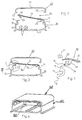
- FIG. 1 shows a cable routing channel, consisting of a channel lower part 10 with an approximately C-shaped cross section, formed by a base 11, two Side walls 12 with cover holding profiles 13 and directed towards the center Shoulder strips 14.
- a bracket 30 consisting of a last body 31 with ends 32 which are place over the shoulder strips 14, and hook-shaped locking profiles 33 on the Bottom.
- the clip 30 is open on the left side and thus enables convenient Adding or removing electrical lines 1.
- the cover holding profiles 13 cooperate on the lower channel part 10.
- Fig. 2 shows the state after completion of the line laying work.
- the left locking profile 33 of the bracket 30 is due to the resilient properties of the Clip 30 on the left shoulder bar 14.
- the upper channel part 20 If the upper channel part 20 is now snapped onto the lower channel part 10, it lies down the upper channel part 20 to the bracket 30 and presses its free end downward.
- the shoulder strip gives way under the action of the sliding slope 34 14 first outwards in order to then latch with the latching profile 33.
- the latching foot 22 of the upper channel part 20 then slides on the sliding bevel 15 down the shoulder bar 14.
- side wall 12, Lid holding profile 13 and shoulder bar 14 pressed in, due to the selected stiffness the clamp 30 yields elastically.
- the latching foot 22 is latched into the lid holding profile 13, the side wall 12 and the springs Clip 30 back elastically.
- the cable routing channel is correct closed without the clips 30 having to be individually latched beforehand.
Landscapes
- Engineering & Computer Science (AREA)
- Architecture (AREA)
- Civil Engineering (AREA)
- Structural Engineering (AREA)
- Installation Of Indoor Wiring (AREA)
- Clamps And Clips (AREA)
- Details Of Indoor Wiring (AREA)
- Multi-Conductor Connections (AREA)
- Insulated Conductors (AREA)
- Measuring Pulse, Heart Rate, Blood Pressure Or Blood Flow (AREA)
- Details Of Aerials (AREA)
Abstract
Description
- Fig. 1
- im Querschnitt einen Leitungsführungskanal mit einseitig für das Nachlegen von Leitungen geöffneter Klammer als Sprengbild,
- Fig. 2
- den Leitungsführungskanal der Fig. 1 nach Beendigung der Verlegungsarbeiten,
- Fig. 3
- den Ausschnitt III aus Fig. 2 in vergrößertem Maßstab und
- Fig. 4
- als Schrägansicht den Leitungsführungskanal der Fig. 1 bis 3 mit aufgesetztem Kanaloberteil.
Claims (3)
- Leitungsführungskanal, im wesentlichen umfassendgekennzeichnet durch die Merkmale:ein Kanalunterteil (10) mitBoden (11),Seitenwänden (12),Deckelhalteprofilen (13) an den Seitenwänden (12)und zum Zentrum hin orientierten Schulterleisten (14),ein Kanaloberteil (20)und wenigstens eine Klammer (30) miteinem Leistenkörper (31)und Rastprofilen (33), die lösbar mit den Schulterleisten (14) verrastbar sind,die Rastprofile (33) besitzen eine Gleitschräge (34), die mit der Schulterleiste (14) kooperiert,die Steifigkeit des Kanalunterteils (10) ist kleiner als die Steifigkeit der Klammer (30),die Steifigkeit der Klammer (30) ist kleiner als die Steifigkeit des Kanaloberteils (20),das aufgesetzte Kanaloberteil (20) berührt die Klammer (30).
- Leitungsführungskanal nach Anspruch 1, gekennzeichnet durch die Merkmale:das Kanaloberteil (20) besitzt Rastfüße (22),die Klammer (30) ist kürzer als der lichte Abstand der Rastfüße (22).
- Leitungsführungskanal nach Anspruch 1 oder 2, gekennzeichnet durch das Merkmal:die Schulterleiste (14) besitzt eine Gleitschräge (15), die mit den Enden des Kanaloberteils (20), insbesondere mit dessen Rastfüßen (22), kooperiert.
Applications Claiming Priority (2)
| Application Number | Priority Date | Filing Date | Title |
|---|---|---|---|
| DE20214499U DE20214499U1 (de) | 2002-09-19 | 2002-09-19 | Leitungsführungskanal |
| DE20214499U | 2002-09-19 |
Publications (2)
| Publication Number | Publication Date |
|---|---|
| EP1401072A1 true EP1401072A1 (de) | 2004-03-24 |
| EP1401072B1 EP1401072B1 (de) | 2007-11-28 |
Family
ID=31896425
Family Applications (1)
| Application Number | Title | Priority Date | Filing Date |
|---|---|---|---|
| EP03018969A Expired - Lifetime EP1401072B1 (de) | 2002-09-19 | 2003-08-21 | Leitungsführungskanal |
Country Status (5)
| Country | Link |
|---|---|
| EP (1) | EP1401072B1 (de) |
| AT (1) | ATE379865T1 (de) |
| DE (2) | DE20214499U1 (de) |
| ES (1) | ES2297082T3 (de) |
| PT (1) | PT1401072E (de) |
Citations (1)
| Publication number | Priority date | Publication date | Assignee | Title |
|---|---|---|---|---|
| DE8328391U1 (de) * | 1983-10-03 | 1985-06-20 | Hans Helmut Nolten KG, 6295 Merenberg | Kabelführungskanal mit Überbrückungsklammer |
-
2002
- 2002-09-19 DE DE20214499U patent/DE20214499U1/de not_active Expired - Lifetime
-
2003
- 2003-08-21 AT AT03018969T patent/ATE379865T1/de not_active IP Right Cessation
- 2003-08-21 ES ES03018969T patent/ES2297082T3/es not_active Expired - Lifetime
- 2003-08-21 DE DE50308674T patent/DE50308674D1/de not_active Expired - Fee Related
- 2003-08-21 PT PT03018969T patent/PT1401072E/pt unknown
- 2003-08-21 EP EP03018969A patent/EP1401072B1/de not_active Expired - Lifetime
Patent Citations (1)
| Publication number | Priority date | Publication date | Assignee | Title |
|---|---|---|---|---|
| DE8328391U1 (de) * | 1983-10-03 | 1985-06-20 | Hans Helmut Nolten KG, 6295 Merenberg | Kabelführungskanal mit Überbrückungsklammer |
Also Published As
| Publication number | Publication date |
|---|---|
| DE20214499U1 (de) | 2004-02-19 |
| PT1401072E (pt) | 2008-02-25 |
| DE50308674D1 (de) | 2008-01-10 |
| ATE379865T1 (de) | 2007-12-15 |
| EP1401072B1 (de) | 2007-11-28 |
| ES2297082T3 (es) | 2008-05-01 |
Similar Documents
| Publication | Publication Date | Title |
|---|---|---|
| DE4032473C3 (de) | Haltevorrichtung für Rohre und eine Abdeckprofilleiste | |
| DE202017007566U1 (de) | Möbel mit einem an einem Laufprofil verfahrbaren Schiebeelement und einer Führungseinrichtung | |
| DE202007012604U1 (de) | Kennzeichnungsvorrichtung für elektrische Leitungen | |
| DE102007008018B4 (de) | Befestigungselement | |
| EP1401072A1 (de) | Leitungsführungskanal | |
| EP1993178B1 (de) | Formteile zur Kaschierung von Schnittkanten an Kabelkanälen | |
| DE29911426U1 (de) | Leitungsführungskanal | |
| DE19737893B4 (de) | Installationskanal mit Abdeckung und Potentialausgleichsklammer für den Potentialausgleich zwischen diesen | |
| DE202020103926U1 (de) | Unterkonstruktion zur Aufnahme von Sichtprofilen sowie Anbauteil | |
| DE1937175A1 (de) | Zwei untereinander verbundene Bauteile | |
| DE29803656U1 (de) | Tür- oder Fensterbeschlag | |
| DE19710625C2 (de) | Kunststoffkettenglied einer Energieführungskette | |
| EP1359650A1 (de) | Anschlussvorrichtung für elektrische Verteiler | |
| EP2134215A1 (de) | Arbeitsmöbel mit kabelkanal | |
| EP2028738B1 (de) | Überbrückungsklammer zur sicherung von kabeln und leitungen in kabelführungskanälen | |
| DE10018883A1 (de) | Regal, insbesondere für Bibliotheken | |
| DE20022356U1 (de) | Installationskanal mit Verbindungsvorrichtung | |
| EP4331436A1 (de) | Federrahmen | |
| EP4434389A1 (de) | Behälter zur lösbaren anbringung an einer haltevorrichtung | |
| EP2608332B1 (de) | Endkappe; Befestigungssystem zur Befestigung eines Profilgehäuses in einem Schranksystem; Verfahren zur Befestigung eines Profilgehäuses in einem Schranksystem | |
| DE29502457U1 (de) | Unterkonstruktion für abgehängte Raumdecken | |
| DE29500258U1 (de) | Halter für Kabel oder Rohre mit einer Abdeckleiste | |
| DE20206869U1 (de) | Leitungsführungskanal | |
| DE102021125767A1 (de) | Bausatz für einen Schiebetürbeschlag, Möbel und Verfahren zum Umrüsten eines Schiebetürbeschlags | |
| DE102006003771A1 (de) | Profil zur Bildung von Rahmenschenkeln eines Trägergestells für einen Schalt- oder/und Verteilerschrank |
Legal Events
| Date | Code | Title | Description |
|---|---|---|---|
| PUAI | Public reference made under article 153(3) epc to a published international application that has entered the european phase |
Free format text: ORIGINAL CODE: 0009012 |
|
| AK | Designated contracting states |
Kind code of ref document: A1 Designated state(s): AT BE BG CH CY CZ DE DK EE ES FI FR GB GR HU IE IT LI LU MC NL PT RO SE SI SK TR |
|
| AX | Request for extension of the european patent |
Extension state: AL LT LV MK |
|
| RIN1 | Information on inventor provided before grant (corrected) |
Inventor name: BUNDSCHUH, JEAN HUBERT Inventor name: SCHNURR, RICHARD |
|
| 17P | Request for examination filed |
Effective date: 20040503 |
|
| AKX | Designation fees paid |
Designated state(s): AT BE BG CH CY CZ DE DK EE ES FI FR GB GR HU IE IT LI LU MC NL PT RO SE SI SK TR |
|
| RAP1 | Party data changed (applicant data changed or rights of an application transferred) |
Owner name: TEHALIT GMBH |
|
| RAP1 | Party data changed (applicant data changed or rights of an application transferred) |
Owner name: TEHALIT GMBH |
|
| 17Q | First examination report despatched |
Effective date: 20061124 |
|
| GRAP | Despatch of communication of intention to grant a patent |
Free format text: ORIGINAL CODE: EPIDOSNIGR1 |
|
| GRAS | Grant fee paid |
Free format text: ORIGINAL CODE: EPIDOSNIGR3 |
|
| GRAA | (expected) grant |
Free format text: ORIGINAL CODE: 0009210 |
|
| AK | Designated contracting states |
Kind code of ref document: B1 Designated state(s): AT BE BG CH CY CZ DE DK EE ES FI FR GB GR HU IE IT LI LU MC NL PT RO SE SI SK TR |
|
| REG | Reference to a national code |
Ref country code: IE Ref legal event code: FG4D Free format text: LANGUAGE OF EP DOCUMENT: GERMAN |
|
| REG | Reference to a national code |
Ref country code: CH Ref legal event code: EP |
|
| REF | Corresponds to: |
Ref document number: 50308674 Country of ref document: DE Date of ref document: 20080110 Kind code of ref document: P |
|
| REG | Reference to a national code |
Ref country code: RO Ref legal event code: EPE |
|
| REG | Reference to a national code |
Ref country code: PT Ref legal event code: SC4A Free format text: AVAILABILITY OF NATIONAL TRANSLATION Effective date: 20080214 |
|
| REG | Reference to a national code |
Ref country code: CH Ref legal event code: NV Representative=s name: PATENTANWAELTE SCHAAD, BALASS, MENZL & PARTNER AG |
|
| GBT | Gb: translation of ep patent filed (gb section 77(6)(a)/1977) |
Effective date: 20080221 |
|
| REG | Reference to a national code |
Ref country code: GR Ref legal event code: EP Ref document number: 20080400349 Country of ref document: GR |
|
| PG25 | Lapsed in a contracting state [announced via postgrant information from national office to epo] |
Ref country code: SE Free format text: LAPSE BECAUSE OF FAILURE TO SUBMIT A TRANSLATION OF THE DESCRIPTION OR TO PAY THE FEE WITHIN THE PRESCRIBED TIME-LIMIT Effective date: 20080228 |
|
| REG | Reference to a national code |
Ref country code: ES Ref legal event code: FG2A Ref document number: 2297082 Country of ref document: ES Kind code of ref document: T3 |
|
| PG25 | Lapsed in a contracting state [announced via postgrant information from national office to epo] |
Ref country code: BG Free format text: LAPSE BECAUSE OF FAILURE TO SUBMIT A TRANSLATION OF THE DESCRIPTION OR TO PAY THE FEE WITHIN THE PRESCRIBED TIME-LIMIT Effective date: 20080228 Ref country code: FI Free format text: LAPSE BECAUSE OF FAILURE TO SUBMIT A TRANSLATION OF THE DESCRIPTION OR TO PAY THE FEE WITHIN THE PRESCRIBED TIME-LIMIT Effective date: 20071128 Ref country code: SI Free format text: LAPSE BECAUSE OF FAILURE TO SUBMIT A TRANSLATION OF THE DESCRIPTION OR TO PAY THE FEE WITHIN THE PRESCRIBED TIME-LIMIT Effective date: 20071128 |
|
| PG25 | Lapsed in a contracting state [announced via postgrant information from national office to epo] |
Ref country code: DK Free format text: LAPSE BECAUSE OF FAILURE TO SUBMIT A TRANSLATION OF THE DESCRIPTION OR TO PAY THE FEE WITHIN THE PRESCRIBED TIME-LIMIT Effective date: 20071128 Ref country code: CZ Free format text: LAPSE BECAUSE OF FAILURE TO SUBMIT A TRANSLATION OF THE DESCRIPTION OR TO PAY THE FEE WITHIN THE PRESCRIBED TIME-LIMIT Effective date: 20071128 |
|
| ET | Fr: translation filed | ||
| PG25 | Lapsed in a contracting state [announced via postgrant information from national office to epo] |
Ref country code: SK Free format text: LAPSE BECAUSE OF FAILURE TO SUBMIT A TRANSLATION OF THE DESCRIPTION OR TO PAY THE FEE WITHIN THE PRESCRIBED TIME-LIMIT Effective date: 20071128 |
|
| PLBE | No opposition filed within time limit |
Free format text: ORIGINAL CODE: 0009261 |
|
| STAA | Information on the status of an ep patent application or granted ep patent |
Free format text: STATUS: NO OPPOSITION FILED WITHIN TIME LIMIT |
|
| 26N | No opposition filed |
Effective date: 20080829 |
|
| PG25 | Lapsed in a contracting state [announced via postgrant information from national office to epo] |
Ref country code: MC Free format text: LAPSE BECAUSE OF NON-PAYMENT OF DUE FEES Effective date: 20080831 |
|
| REG | Reference to a national code |
Ref country code: CH Ref legal event code: PL |
|
| GBPC | Gb: european patent ceased through non-payment of renewal fee |
Effective date: 20080821 |
|
| PG25 | Lapsed in a contracting state [announced via postgrant information from national office to epo] |
Ref country code: EE Free format text: LAPSE BECAUSE OF FAILURE TO SUBMIT A TRANSLATION OF THE DESCRIPTION OR TO PAY THE FEE WITHIN THE PRESCRIBED TIME-LIMIT Effective date: 20071128 |
|
| NLV4 | Nl: lapsed or anulled due to non-payment of the annual fee |
Effective date: 20090301 |
|
| PG25 | Lapsed in a contracting state [announced via postgrant information from national office to epo] |
Ref country code: NL Free format text: LAPSE BECAUSE OF NON-PAYMENT OF DUE FEES Effective date: 20090301 |
|
| REG | Reference to a national code |
Ref country code: PT Ref legal event code: MM4A Free format text: LAPSE DUE TO NON-PAYMENT OF FEES Effective date: 20090521 |
|
| REG | Reference to a national code |
Ref country code: FR Ref legal event code: ST Effective date: 20090430 |
|
| PG25 | Lapsed in a contracting state [announced via postgrant information from national office to epo] |
Ref country code: GR Free format text: LAPSE BECAUSE OF NON-PAYMENT OF DUE FEES Effective date: 20090304 Ref country code: LI Free format text: LAPSE BECAUSE OF NON-PAYMENT OF DUE FEES Effective date: 20080831 Ref country code: CH Free format text: LAPSE BECAUSE OF NON-PAYMENT OF DUE FEES Effective date: 20080831 |
|
| PG25 | Lapsed in a contracting state [announced via postgrant information from national office to epo] |
Ref country code: BE Free format text: LAPSE BECAUSE OF NON-PAYMENT OF DUE FEES Effective date: 20080831 Ref country code: IE Free format text: LAPSE BECAUSE OF NON-PAYMENT OF DUE FEES Effective date: 20080821 Ref country code: CY Free format text: LAPSE BECAUSE OF FAILURE TO SUBMIT A TRANSLATION OF THE DESCRIPTION OR TO PAY THE FEE WITHIN THE PRESCRIBED TIME-LIMIT Effective date: 20071128 |
|
| PG25 | Lapsed in a contracting state [announced via postgrant information from national office to epo] |
Ref country code: IT Free format text: LAPSE BECAUSE OF NON-PAYMENT OF DUE FEES Effective date: 20080821 Ref country code: DE Free format text: LAPSE BECAUSE OF NON-PAYMENT OF DUE FEES Effective date: 20090303 Ref country code: FR Free format text: LAPSE BECAUSE OF NON-PAYMENT OF DUE FEES Effective date: 20080901 Ref country code: PT Free format text: LAPSE BECAUSE OF NON-PAYMENT OF DUE FEES Effective date: 20090521 |
|
| REG | Reference to a national code |
Ref country code: ES Ref legal event code: FD2A Effective date: 20080822 |
|
| PG25 | Lapsed in a contracting state [announced via postgrant information from national office to epo] |
Ref country code: AT Free format text: LAPSE BECAUSE OF NON-PAYMENT OF DUE FEES Effective date: 20080821 |
|
| PG25 | Lapsed in a contracting state [announced via postgrant information from national office to epo] |
Ref country code: GB Free format text: LAPSE BECAUSE OF NON-PAYMENT OF DUE FEES Effective date: 20080821 |
|
| PG25 | Lapsed in a contracting state [announced via postgrant information from national office to epo] |
Ref country code: ES Free format text: LAPSE BECAUSE OF NON-PAYMENT OF DUE FEES Effective date: 20080822 |
|
| PG25 | Lapsed in a contracting state [announced via postgrant information from national office to epo] |
Ref country code: RO Free format text: LAPSE BECAUSE OF NON-PAYMENT OF DUE FEES Effective date: 20071128 |
|
| PG25 | Lapsed in a contracting state [announced via postgrant information from national office to epo] |
Ref country code: LU Free format text: LAPSE BECAUSE OF NON-PAYMENT OF DUE FEES Effective date: 20080821 Ref country code: HU Free format text: LAPSE BECAUSE OF FAILURE TO SUBMIT A TRANSLATION OF THE DESCRIPTION OR TO PAY THE FEE WITHIN THE PRESCRIBED TIME-LIMIT Effective date: 20080529 |
|
| PG25 | Lapsed in a contracting state [announced via postgrant information from national office to epo] |
Ref country code: TR Free format text: LAPSE BECAUSE OF FAILURE TO SUBMIT A TRANSLATION OF THE DESCRIPTION OR TO PAY THE FEE WITHIN THE PRESCRIBED TIME-LIMIT Effective date: 20071128 |