EP1401073A1 - Verdrahtungskanal - Google Patents
Verdrahtungskanal Download PDFInfo
- Publication number
- EP1401073A1 EP1401073A1 EP03019055A EP03019055A EP1401073A1 EP 1401073 A1 EP1401073 A1 EP 1401073A1 EP 03019055 A EP03019055 A EP 03019055A EP 03019055 A EP03019055 A EP 03019055A EP 1401073 A1 EP1401073 A1 EP 1401073A1
- Authority
- EP
- European Patent Office
- Prior art keywords
- webs
- strip
- retaining
- support surface
- cable retention
- Prior art date
- Legal status (The legal status is an assumption and is not a legal conclusion. Google has not performed a legal analysis and makes no representation as to the accuracy of the status listed.)
- Withdrawn
Links
- 210000002105 tongue Anatomy 0.000 claims abstract description 12
- 230000014759 maintenance of location Effects 0.000 claims description 21
- 230000008878 coupling Effects 0.000 abstract 1
- 238000010168 coupling process Methods 0.000 abstract 1
- 238000005859 coupling reaction Methods 0.000 abstract 1
- 238000010276 construction Methods 0.000 description 1
- 238000009434 installation Methods 0.000 description 1
- 230000003068 static effect Effects 0.000 description 1
Images
Classifications
-
- H—ELECTRICITY
- H02—GENERATION; CONVERSION OR DISTRIBUTION OF ELECTRIC POWER
- H02G—INSTALLATION OF ELECTRIC CABLES OR LINES, OR OF COMBINED OPTICAL AND ELECTRIC CABLES OR LINES
- H02G3/00—Installations of electric cables or lines or protective tubing therefor in or on buildings, equivalent structures or vehicles
- H02G3/02—Details
- H02G3/04—Protective tubing or conduits, e.g. cable ladders or cable troughs
- H02G3/0406—Details thereof
- H02G3/0418—Covers or lids; Their fastenings
-
- H—ELECTRICITY
- H02—GENERATION; CONVERSION OR DISTRIBUTION OF ELECTRIC POWER
- H02G—INSTALLATION OF ELECTRIC CABLES OR LINES, OR OF COMBINED OPTICAL AND ELECTRIC CABLES OR LINES
- H02G3/00—Installations of electric cables or lines or protective tubing therefor in or on buildings, equivalent structures or vehicles
- H02G3/02—Details
- H02G3/04—Protective tubing or conduits, e.g. cable ladders or cable troughs
- H02G3/0406—Details thereof
-
- H—ELECTRICITY
- H02—GENERATION; CONVERSION OR DISTRIBUTION OF ELECTRIC POWER
- H02G—INSTALLATION OF ELECTRIC CABLES OR LINES, OR OF COMBINED OPTICAL AND ELECTRIC CABLES OR LINES
- H02G3/00—Installations of electric cables or lines or protective tubing therefor in or on buildings, equivalent structures or vehicles
- H02G3/02—Details
- H02G3/04—Protective tubing or conduits, e.g. cable ladders or cable troughs
- H02G3/0437—Channels
- H02G3/045—Channels provided with perforations or slots permitting introduction or exit of wires
Definitions
- the invention relates to wiring channels according to the preamble of claim 1.
- a wiring channel which consists of a Channel lower part with a U-shaped cross section consists of a bottom and two side walls.
- the sidewalls are formed by regular spaced webs, the ends of which are shaped in such a way that a cover can be detached can be snapped on.
- cable retention strips are provided. These have a foot that is shaped so that the cable retention strip clamps between two webs can be attached.
- the present invention is therefore based on the object Specify wiring channel of the type mentioned, the retaining strips not only can be assembled and disassembled at any time but also in the Height adjustable and have a firm hold.
- a major advantage of the cable retention strip according to the invention is the stable Connection between bar and channel, due to the fact that the bar foot is off consists of three arrow-shaped elements, on the one hand the arrow-shaped retaining lug, which can be inserted through the slots, and the other from the two resilient, arrow-shaped retaining tongues, which the two webs additionally from the outside take.
- the cable retention strip according to the invention can be mount at any point and at any height of the cable duct, even if the cable duct is already more or less with cables, lines or Wires is filled. Due to the large contact area, the pressure load is of the individual webs reduced. At the same time, the static friction is so high that the cable retention strip is firmly seated, but can be moved at any time if necessary can be removed.
- the retaining tongue is designed as a two-armed lever and has a release arm that the installer can easily operate. Thereby the arrow-shaped retaining tongues spread from the two webs and the Arrow-shaped retaining lug can come out of the slot between the two webs be pulled out.
- the retaining strip has molded-in Predetermined breaking points. This allows the length of the retaining bar to be conveniently adjusted to the location required length are brought.
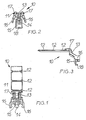
- FIG. 1 to 3 show a top view, front view and side view Cable retaining strip 10.
- This essentially consists of a retaining strip 11, here with molded-in predetermined breaking lines 12, one oriented approximately perpendicular to it Support surface 15, a connecting bar 13 between the holding bar 11 and the support surface 15, an arrow-shaped retaining lug 14 on the support surface 15 through the slots insertable between two webs of a wiring channel (FIG. 4) and is anchored, and two resilient, arrow-shaped retaining tongues 16.
- the distance between the arrow-shaped retaining lug 14 and the arrow-shaped retaining tongues 16 matched to the width of the channel webs 2 (see FIG. 4).
- the holding tongues 16 are in this embodiment as a two-armed lever trained, whereby they have release arms 17 that the installer comfortably with fingers can squeeze when the cable retention bar 10 from Wiring duct to be removed.
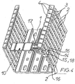
- Fig. 4 shows the lower part of a wiring channel, essentially formed by a floor 1, by a plurality of flexible, separated by slots 3 Webs 2 formed side walls and lid holding profiles 4 at the free ends the webs 2.
- a cable retention strip 10 On two adjacent webs 2 there is a cable retention strip 10 attached.
- the arrow-shaped retaining lug 14 is through the slot 3 between two inserted adjacent webs 2, the webs 2 springing out, and anchored behind the two webs 2.
- the two holding tongues 16 have resiliently applied from the outside against the two adjacent webs 2. This sits the cable retention strip 10 optimally tight. By squeezing the two Release arms 17, the holding tongues 16 can spread when the Cable retention strip 10 moved in height or removed entirely should.
Landscapes
- Engineering & Computer Science (AREA)
- Architecture (AREA)
- Civil Engineering (AREA)
- Structural Engineering (AREA)
- Installation Of Indoor Wiring (AREA)
- Details Of Indoor Wiring (AREA)
Abstract
Description
- Fig. 1
- eine Draufsicht auf eine Kabelrückhalteleiste,
- Fig. 2
- eine Frontsicht der Kabelrückhalteleiste der Fig. 1,
- Fig. 3
- eine Seitenansicht der Kabelrückhalteleiste der Fig. 1 und 2 und
- Fig. 4
- eine Schrägansicht eines Verdrahtungskanals mit montierter Kabelrückhalteleiste.
Claims (4)
- Verdrahtungskanal, im wesentlichen umfassendgekennzeichnet durch die Merkmale:ein Kanalunterteil miteinem Boden (1),Seitenwänden, gebildet durch eine Vielzahl von durch Schlitze (3) getrennten, flexiblen Stegen (2)und gegebenenfalls Deckelhalteprofilen (4) an den freien Enden der Stege (2)und wenigstens eine Kabelrückhalteleiste (10), lösbar zu befestigen an den Stegen(2),die Kabelrückhalteleiste (10) ist gebildet durcheine Halteleiste (11),eine etwa senkrecht dazu orientierte Stützfläche (15),eine Verbindungsleiste (13) zwischen Halteleiste (11) und Stützfläche (15),eine pfeilförmige Haltenase (14), die durch die Schlitze (3) hindurchsteckbar und so an zwei Stegen (2) verankerbar istund zwei federnde, pfeilförmige Haltezungen (16), die diese zwei Stege (2) von außen ergreifen.
- Kanal nach Anspruch 1, gekennzeichnet durch die Merkmale:die Haltezunge (16)ist als zweiarmiger Hebel ausgebildetund besitzt einen Lösearm (17).
- Kanal nach Anspruch 1 oder 2, gekennzeichnet durch die Merkmale:an der Stützfläche (15) ist ein Positioniernocken (18) angeformt,der Positioniernocken (18) passt zwischen die zwei Stege (2).
- Kanal nach einem der Ansprüche 1 bis 3, gekennzeichnet durch das Merkmal:die Halteleiste (11) besitzt eingeformte Sollbruchstellen (12).
Applications Claiming Priority (2)
| Application Number | Priority Date | Filing Date | Title |
|---|---|---|---|
| DE20214553U DE20214553U1 (de) | 2002-09-20 | 2002-09-20 | Verdrahtungskanal |
| DE20214553U | 2002-09-20 |
Publications (1)
| Publication Number | Publication Date |
|---|---|
| EP1401073A1 true EP1401073A1 (de) | 2004-03-24 |
Family
ID=31896430
Family Applications (1)
| Application Number | Title | Priority Date | Filing Date |
|---|---|---|---|
| EP03019055A Withdrawn EP1401073A1 (de) | 2002-09-20 | 2003-08-22 | Verdrahtungskanal |
Country Status (2)
| Country | Link |
|---|---|
| EP (1) | EP1401073A1 (de) |
| DE (1) | DE20214553U1 (de) |
Cited By (1)
| Publication number | Priority date | Publication date | Assignee | Title |
|---|---|---|---|---|
| EP1850434A1 (de) * | 2006-04-24 | 2007-10-31 | Bocchiotti S.p.A. Societa' per l'Industria Elettrotecnica | Stromkabelbefestigungsvorrichtung für Verdrahtungskanäle |
Families Citing this family (1)
| Publication number | Priority date | Publication date | Assignee | Title |
|---|---|---|---|---|
| DE102021133811B4 (de) | 2021-12-20 | 2024-04-25 | Rittal Gmbh & Co. Kg | Kabelkanal für automatisierte Verdrahtung einer elektrischen Steuerungs- oder Schaltanlage |
Citations (1)
| Publication number | Priority date | Publication date | Assignee | Title |
|---|---|---|---|---|
| US3890459A (en) * | 1974-06-17 | 1975-06-17 | Panduit Corp | Wireway system and retaining finger for use therein |
-
2002
- 2002-09-20 DE DE20214553U patent/DE20214553U1/de not_active Expired - Lifetime
-
2003
- 2003-08-22 EP EP03019055A patent/EP1401073A1/de not_active Withdrawn
Patent Citations (1)
| Publication number | Priority date | Publication date | Assignee | Title |
|---|---|---|---|---|
| US3890459A (en) * | 1974-06-17 | 1975-06-17 | Panduit Corp | Wireway system and retaining finger for use therein |
Cited By (1)
| Publication number | Priority date | Publication date | Assignee | Title |
|---|---|---|---|---|
| EP1850434A1 (de) * | 2006-04-24 | 2007-10-31 | Bocchiotti S.p.A. Societa' per l'Industria Elettrotecnica | Stromkabelbefestigungsvorrichtung für Verdrahtungskanäle |
Also Published As
| Publication number | Publication date |
|---|---|
| DE20214553U1 (de) | 2004-03-04 |
Similar Documents
| Publication | Publication Date | Title |
|---|---|---|
| AT395668B (de) | Gestell-system fuer den schwachstrom-anlagebau, insbesondere fuer verteiler-anlagen | |
| DE2927114A1 (de) | Regalsystem | |
| EP0004603B1 (de) | Verbinder für zwei sich kreuzende Schienen | |
| DE202009003250U1 (de) | Aus mehreren Kennzeichnungsvorrichtungen zusammenstellbare Kennzeichnungs-Reihenanordnung | |
| DE9317739U1 (de) | Kabelverlegungssystem | |
| DE2755185C2 (de) | Deckenkassette für eine gitterartige Unterdecke | |
| DE19728284C2 (de) | Elektrifiziereinrichtung für ein Büromöbel | |
| DE7711728U1 (de) | Kabelinstallationskanal | |
| EP0167032A2 (de) | Aufhängevorrichtung für Wandplatten mit einer an einer Wand befestigbaren Querleiste od. dgl. und daran eingehängten, die Wandplatten tragenden Haken | |
| DE69601751T2 (de) | Vorrichtung zum Befestigen einer horizontalen Konsole auf einem vertikalen Ständer mittels einem Schlüssel für Verriegelung | |
| DE20214553U1 (de) | Verdrahtungskanal | |
| DE2012862C2 (de) | Halteklammer für Kabel | |
| EP1376797B1 (de) | Verdrahtungskanal | |
| DE19737893B4 (de) | Installationskanal mit Abdeckung und Potentialausgleichsklammer für den Potentialausgleich zwischen diesen | |
| DE2515573A1 (de) | Leitungskanal zum halten und fuehren von kabeln oder leitungen | |
| DE69206475T2 (de) | Bodenrahmen für elektrischen Kasten. | |
| DE2109613A1 (de) | Kabelkanal mit Trennwanden | |
| DE2049509C3 (de) | Halterung für Anschlußelementeträger | |
| DE3240895C2 (de) | ||
| DE1293879C2 (de) | Trennwand fuer einen Kabelkanal | |
| DE20220848U1 (de) | Gehäuse oder Gestell mit einer Kabelführungsvorrichtung | |
| EP0399389A1 (de) | Kabelkanal | |
| DE102024004527A1 (de) | Energieführungsketten und/oder Kabelführungskette | |
| DE2516845C3 (de) | Traggerippe für eine Bandrasterdecke | |
| CH687947A5 (de) | Verteilergestell fuer Telekommunikationsanlagen. |
Legal Events
| Date | Code | Title | Description |
|---|---|---|---|
| PUAI | Public reference made under article 153(3) epc to a published international application that has entered the european phase |
Free format text: ORIGINAL CODE: 0009012 |
|
| AK | Designated contracting states |
Kind code of ref document: A1 Designated state(s): AT BE BG CH CY CZ DE DK EE ES FI FR GB GR HU IE IT LI LU MC NL PT RO SE SI SK TR |
|
| AX | Request for extension of the european patent |
Extension state: AL LT LV MK |
|
| 17P | Request for examination filed |
Effective date: 20040503 |
|
| AKX | Designation fees paid |
Designated state(s): AT BE BG CH CY CZ DE DK EE ES FI FR GB GR HU IE IT LI LU MC NL PT RO SE SI SK TR |
|
| RAP1 | Party data changed (applicant data changed or rights of an application transferred) |
Owner name: TEHALIT GMBH |
|
| RAP1 | Party data changed (applicant data changed or rights of an application transferred) |
Owner name: TEHALIT GMBH |
|
| 17Q | First examination report despatched |
Effective date: 20070507 |
|
| GRAP | Despatch of communication of intention to grant a patent |
Free format text: ORIGINAL CODE: EPIDOSNIGR1 |
|
| STAA | Information on the status of an ep patent application or granted ep patent |
Free format text: STATUS: THE APPLICATION IS DEEMED TO BE WITHDRAWN |
|
| 18D | Application deemed to be withdrawn |
Effective date: 20101103 |