EP1401236A1 - Wandlermontagesystem und Verfahren - Google Patents
Wandlermontagesystem und Verfahren Download PDFInfo
- Publication number
- EP1401236A1 EP1401236A1 EP02020321A EP02020321A EP1401236A1 EP 1401236 A1 EP1401236 A1 EP 1401236A1 EP 02020321 A EP02020321 A EP 02020321A EP 02020321 A EP02020321 A EP 02020321A EP 1401236 A1 EP1401236 A1 EP 1401236A1
- Authority
- EP
- European Patent Office
- Prior art keywords
- adapter
- housing
- transducer
- mounting
- loudspeaker
- Prior art date
- Legal status (The legal status is an assumption and is not a legal conclusion. Google has not performed a legal analysis and makes no representation as to the accuracy of the status listed.)
- Withdrawn
Links
Images


Classifications
-
- H—ELECTRICITY
- H04—ELECTRIC COMMUNICATION TECHNIQUE
- H04M—TELEPHONIC COMMUNICATION
- H04M1/00—Substation equipment, e.g. for use by subscribers
- H04M1/60—Substation equipment, e.g. for use by subscribers including speech amplifiers
- H04M1/62—Constructional arrangements
-
- H—ELECTRICITY
- H04—ELECTRIC COMMUNICATION TECHNIQUE
- H04M—TELEPHONIC COMMUNICATION
- H04M1/00—Substation equipment, e.g. for use by subscribers
- H04M1/02—Constructional features of telephone sets
- H04M1/03—Constructional features of telephone transmitters or receivers, e.g. telephone hand-sets
-
- H—ELECTRICITY
- H04—ELECTRIC COMMUNICATION TECHNIQUE
- H04R—LOUDSPEAKERS, MICROPHONES, GRAMOPHONE PICK-UPS OR LIKE ACOUSTIC ELECTROMECHANICAL TRANSDUCERS; ELECTRIC HEARING AIDS; PUBLIC ADDRESS SYSTEMS
- H04R1/00—Details of transducers, loudspeakers or microphones
- H04R1/02—Casings; Cabinets ; Supports therefor; Mountings therein
Definitions
- the invention relates generally to the mounting of transducers such as loudspeakers or microphones, and, more specifically, to the mounting of such elements into portable devices.
- the position of the loudspeaker has to be fixed already when designing the form of the housing. This means that the mould has to be redesigned and reconstructed always when there are any changes with the positioning or orienting of the loudspeaker, one essential limitation for the positioning of the loudspeaker being the need to have a hole close to the loudspeaker enabling sound coming out of the housing of the device.
- FIG 1A shows a loudspeaker mounting mechanism according to published patent applications GB 2 225 192 A and EP 0 453 061 A2.
- the loudspeaker 12 is mounted to the housing 11 using a mounting part 13 which is fixed in the housing 11.
- the housing 11 has also an acoustically more conductive part 14 which has punctures in the housing for allowing easy passage of the sound waves.
- FIG. 1B shows another loudspeaker mounting system according to the published patent application EP 0 166 198 A2.
- a removable adapter 15 is used for holding a loudspeaker 12.
- the adapter 15 is fixed to the bottom part 16 of the housing using fingers 17' which stick to the corresponding fingers 17 that are located in the bottom part 16 of the housing.
- the loudspeaker 12 is positioned into the adapter 15.
- the top part 11 of the housing is fixed to support the loudspeaker 12.
- Such a mechanism is nevertheless too complicated to be applied for thin, portable devices such as mobile terminals.
- the loudspeaker should be placed into an acoustically favourable position, but the design does not necessarily always allow that. This is why acoustic and the design strongly depend on each other. It is also possible that the shape of the device has to be redesigned few times which makes the design of new mobile terminals much more expensive and slower.
- the displays of the mobile terminals have also grown and the keypad may also at least in some models take lots of space. These parts of the devices have a specific effect on the acoustical design, because the slit between the display window and the housing can cause lots of acoustical problems. Similarly, it the device is a mobile terminal, any other slits between other elements of the mobile terminal may be problematic.
- the loudspeaker when the loudspeaker is positioned over the slit between the display and the housing in order to maximise the comfort of use, it is extremely difficult to make a proper sealing for the loudspeaker, because the slit between the display and the housing can easily be a few tenths of a millimetre.
- the microphone there are similar problems, for example, when the microphone is located close to the keypad.
- behind the display there usually are printings which also make it almost impossible to integrate the loudspeaker together with the display, i.e. place the loudspeaker into the vicinity of the display.
- An adapter for mounting a transducer onto a housing of a device includes i) a first mounting part adapted to mount the adapter into the vicinity of an acoustically well conductive part of the housing, ii) a punctured part for enabling the passage of sound waves to/from the transducer from/to the exterior of the device, and iii) a second mounting part for mounting the transducer to the adapter.
- a method for fastening a transducer on a housing of a device comprises the steps of: i) mounting an adapter to vicinity of an acoustically well conductive part of the housing, and ii) mounting the transducer to the adapter, the adapter being equipped with a punctured part for enabling the passage of sound waves to/from the transducer from/to the exterior of the device, the punctured part being adapted to match the acoustically well conductive part of the housing.
- FIG. 2 illustrates a loudspeaker adapter in accordance with the present invention.
- the loudspeaker 12 is to be installed onto a housing 11 of a mobile phone.
- the housing 11 has holes within the region marked by dotted box 21. The purpose of the holes is twofold.
- transducer 12 Firstly, their purpose is to act as an acoustical conduit for some sound waves coming from transducer 12 if the transducer is a loudspeaker, or to act an acoustical passage to the transducer if the transducer is a microphone. In the following, it is assumed that the transducer 12 is a loudspeaker.
- the purpose of the holes in the region 21 is to act as responsive attaching means for fingers marked by the dotted box 22 of the loudspeaker adapter 20.
- the fingers 22 stick mechanically into the housing 11 at the region 21.
- the loudspeaker adapter 20 has a second mounting part 13 for mounting the transducer 12 to the adapter 20. Between the mounting part 22 and the second mounting part 13 there is an area 23 marked with a dotted box.
- the area 23 includes holes for the sound waves to pass.
- the holes in the region 23 enable the sound waves to exit the loudspeaker 12 and to proceed through the area formed by first mounting part 22 and the acoustically well conductive part 21 of the housing 11 to the exterior of the device.
- the loudspeaker adapter 20 will shorten the development time of a new product, because it can be redesigned before the complete shape of the device is complete, as long as the interface area between the loudspeaker adapter 20 and the housing 11 does not change. Because the loudspeaker adapter 20 is small and simple, the price for the mould for it will be low. If any changes are necessary, making a completely new mould is inexpensive compared to having to make a new mould for the complete device.
- the possible slit between the display window and the housing can cause lots of acoustical problems.
- the device is a mobile terminal
- any other slits between other elements of the mobile terminal may be problematic.
- These problems can now be avoided by using a loudspeaker adapter 20.
- the problem probability is high if a loudspeaker adapter 20 is not used. It has turned out very difficult to seal the junction between any two parts, giving leaks in the acoustic design. The leaks are unacceptable in the sense that they easily ruin the acoustical quality of the device.
- FIG. 3 illustrates a second embodiment of the present invention.
- the bottom 32 of the adapter 20 is made of at least one elastic material such as silicon.
- the adapter 20 has holes 34 and members 35 for acoustical and mounting purposes.
- the members 35 constitute the first mounting means 22.
- the holes 34 constitute the area 23 between the first mounting means 22 and the second mounting means 30.
- the adapter includes load holes 31 that stabilise the acoustical load caused by the loudspeaker 12.
- load holes 31 that stabilise the acoustical load caused by the loudspeaker 12.
- attaching members 33 which improve the mechanical fixing of the adapter 20 to the housing 11.
- the adapter 20 has second mounting means 13 which in this case have a shape of a circle in order to accommodate the loudspeaker 12 and seal it properly.
- the second mounting means 13 may consist of an elastic material such as silicon or rubber. Holes 34 within the area 23 lead through the loudspeaker adapter 23
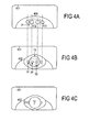
- Figure 4A illustrates a mobile terminal which has a housing 401 and a display 402.
- the housing 401 consists of moulded plastic
- the display 402 is a liquid crystal display.
- the width of the slit is few tenths of millimetre thus making it more difficult to obtain a proper sealing for the loudspeaker that is going to be installed on the housing.
- Part of the transducer membrane is located above the display 402. Further, if the background of the display 402 contains printings such as the displays of some manufacturers do, the printings make the sealing even more challenging.
- the display has two holes 412 corresponding to the area 21 of the previous examples and again marked with a dotted box. It is not significant that the holes 401 are located in the display 402, but they could be located in the housing 401 as well. Further, the display contains also holes 410 acting as load holes and improving the fastening of the loudspeaker adapter.
- Figure 4B shows the system of Figure 4A after the loudspeaker adapter 20 has been installed on the place. Now the holes 34 corresponding to the area marked with dust box 23 are visible. Further, the load holes 34 and 31 are visible. The second mounting means 13 are marked with a circle.
- Figure 4C illustrates the composition of Figure 4B after the loudspeaker 12 has been installed.
- the load holes 31 are still visible. They balance and stabilise the acoustical load by opening a channel from the exterior of the housing to the back side of the loudspeaker 12.
- the loudspeaker 12 is mounted onto a housing 11 using a speaker adapter 20 which includes i) a first mounting part 22 adapted to mount the speaker adapter 20 into the vicinity of an acoustically well conductive part 21 of the housing 11, ii) a punctured part 23 for enabling the passage of sound waves from the loudspeaker 23 to the exterior of the device, and iii) a second mounting part 13 for mounting the loudspeaker 12 to the loudspeaker adapter 20.
- a speaker adapter 20 which includes i) a first mounting part 22 adapted to mount the speaker adapter 20 into the vicinity of an acoustically well conductive part 21 of the housing 11, ii) a punctured part 23 for enabling the passage of sound waves from the loudspeaker 23 to the exterior of the device, and iii) a second mounting part 13 for mounting the loudspeaker 12 to the loudspeaker adapter 20.
- the loudspeaker adapter 20 can be made of at least one elastic material. Further, the loudspeaker adapter 20 may be arranged to provide an acoustical sealing between the housing and a construction element such as a display as into the vicinity of the house.
- the loudspeaker adapter 20 can be used for fitting also another kind of transducer, such as a microphone, to any kind of housing 11.
- a transducer such as a microphone
Landscapes
- Engineering & Computer Science (AREA)
- Signal Processing (AREA)
- Details Of Audible-Bandwidth Transducers (AREA)
- Obtaining Desirable Characteristics In Audible-Bandwidth Transducers (AREA)
- Telephone Set Structure (AREA)
Priority Applications (1)
| Application Number | Priority Date | Filing Date | Title |
|---|---|---|---|
| EP02020321A EP1401236A1 (de) | 2002-09-11 | 2002-09-11 | Wandlermontagesystem und Verfahren |
Applications Claiming Priority (1)
| Application Number | Priority Date | Filing Date | Title |
|---|---|---|---|
| EP02020321A EP1401236A1 (de) | 2002-09-11 | 2002-09-11 | Wandlermontagesystem und Verfahren |
Publications (1)
| Publication Number | Publication Date |
|---|---|
| EP1401236A1 true EP1401236A1 (de) | 2004-03-24 |
Family
ID=31896849
Family Applications (1)
| Application Number | Title | Priority Date | Filing Date |
|---|---|---|---|
| EP02020321A Withdrawn EP1401236A1 (de) | 2002-09-11 | 2002-09-11 | Wandlermontagesystem und Verfahren |
Country Status (1)
| Country | Link |
|---|---|
| EP (1) | EP1401236A1 (de) |
Cited By (1)
| Publication number | Priority date | Publication date | Assignee | Title |
|---|---|---|---|---|
| EP1583332A3 (de) * | 2004-03-30 | 2010-09-22 | NEC Corporation | Mobilstation mit einem Rohr zum Führen des Klangs von einem Lautsprecher |
Citations (4)
| Publication number | Priority date | Publication date | Assignee | Title |
|---|---|---|---|---|
| US4908737A (en) * | 1987-12-08 | 1990-03-13 | Mitsubishi Denki Kabushiki Kaisha | Mounting structure of a small-sized acoustic component |
| WO2000076183A1 (en) * | 1999-06-03 | 2000-12-14 | Telefonaktiebolaget Lm Ericsson (Publ) | Surface mounting of mobile telephone speaker unit |
| US6321070B1 (en) * | 1998-05-14 | 2001-11-20 | Motorola, Inc. | Portable electronic device with a speaker assembly |
| WO2002031401A2 (en) * | 2000-10-11 | 2002-04-18 | Molex Incorporated | Holder for electronic device, such as a microphone |
-
2002
- 2002-09-11 EP EP02020321A patent/EP1401236A1/de not_active Withdrawn
Patent Citations (4)
| Publication number | Priority date | Publication date | Assignee | Title |
|---|---|---|---|---|
| US4908737A (en) * | 1987-12-08 | 1990-03-13 | Mitsubishi Denki Kabushiki Kaisha | Mounting structure of a small-sized acoustic component |
| US6321070B1 (en) * | 1998-05-14 | 2001-11-20 | Motorola, Inc. | Portable electronic device with a speaker assembly |
| WO2000076183A1 (en) * | 1999-06-03 | 2000-12-14 | Telefonaktiebolaget Lm Ericsson (Publ) | Surface mounting of mobile telephone speaker unit |
| WO2002031401A2 (en) * | 2000-10-11 | 2002-04-18 | Molex Incorporated | Holder for electronic device, such as a microphone |
Cited By (1)
| Publication number | Priority date | Publication date | Assignee | Title |
|---|---|---|---|---|
| EP1583332A3 (de) * | 2004-03-30 | 2010-09-22 | NEC Corporation | Mobilstation mit einem Rohr zum Führen des Klangs von einem Lautsprecher |
Similar Documents
| Publication | Publication Date | Title |
|---|---|---|
| CN103618984B (zh) | 一种扬声器模组及其制造方法 | |
| US7953461B2 (en) | Mobile terminal and speaker | |
| CN201286164Y (zh) | 可变指向性传声器组装体 | |
| CN102510547A (zh) | 防水结构 | |
| CN109246260B (zh) | 移动终端及其壳体组件 | |
| WO2021197114A1 (zh) | 一种电子设备 | |
| CN110957612B (zh) | 连接装置以及包括连接装置的电子装置 | |
| EP2356822B1 (de) | Elektronische geräte samt auf einer basisplatte angeordneten akustischen aktuatoren sowie verwandte verfahren und mobilfunktelefone | |
| US10264335B1 (en) | Speaker box and method for assembling same | |
| JP2003513577A (ja) | 電気音響通信装置 | |
| US20100113087A1 (en) | Electronic Devices Including Substrate Mounted Acoustic Actuators and Related Methods and Mobile Radiotelephones | |
| WO2019062997A1 (zh) | 一种终端设备以及出音装置 | |
| EP1401236A1 (de) | Wandlermontagesystem und Verfahren | |
| CN109714657B (zh) | 扬声器组件、便携式电子设备及扬声器组件的组装方法 | |
| CN111464680A (zh) | 电子设备 | |
| CN218634230U (zh) | 发声装置以及电子设备 | |
| EP0965215A1 (de) | Tragbares gerät für sprachkommunikation mit einem akustischen leiter in dem klappdeckel | |
| CN117857677A (zh) | 电子设备及声音控制方法 | |
| KR100663490B1 (ko) | 안테나 실장 공간을 이용하는 휴대 단말기의 스피커 장치 | |
| KR100768137B1 (ko) | 마이크로스피커 모듈의 백볼륨 단자구조 | |
| JP2007096843A (ja) | 携帯端末装置 | |
| CN216565223U (zh) | 听筒模组及电子设备 | |
| CN109327774A (zh) | 一种扬声器外壳及其成型方法 | |
| US20200328495A1 (en) | Side Mounting of MEMS Microphones on Tapered Horn Antenna | |
| CN220493136U (zh) | 一种电子产品的喇叭组件及电子产品 |
Legal Events
| Date | Code | Title | Description |
|---|---|---|---|
| PUAI | Public reference made under article 153(3) epc to a published international application that has entered the european phase |
Free format text: ORIGINAL CODE: 0009012 |
|
| 17P | Request for examination filed |
Effective date: 20040119 |
|
| AK | Designated contracting states |
Kind code of ref document: A1 Designated state(s): AT BE BG CH CY CZ DE DK EE ES FI FR GB GR IE IT LI LU MC NL PT SE SK TR |
|
| AX | Request for extension of the european patent |
Extension state: AL LT LV MK RO SI |
|
| AKX | Designation fees paid |
Designated state(s): AT BE BG |
|
| RBV | Designated contracting states (corrected) |
Designated state(s): DE FR GB |
|
| REG | Reference to a national code |
Ref country code: DE Ref legal event code: 8566 |
|
| RAP1 | Party data changed (applicant data changed or rights of an application transferred) |
Owner name: BENQ MOBILE GMBH & CO. OHG |
|
| 19U | Interruption of proceedings before grant |
Effective date: 20070101 |
|
| 19W | Proceedings resumed before grant after interruption of proceedings |
Effective date: 20070702 |
|
| 19W | Proceedings resumed before grant after interruption of proceedings |
Effective date: 20071130 |
|
| 17Q | First examination report despatched |
Effective date: 20080417 |
|
| STAA | Information on the status of an ep patent application or granted ep patent |
Free format text: STATUS: THE APPLICATION IS DEEMED TO BE WITHDRAWN |
|
| 18D | Application deemed to be withdrawn |
Effective date: 20081028 |