EP1401242A2 - Feedbackkompensation für Hörgeräte mit Systemabstandsschätzung - Google Patents
Feedbackkompensation für Hörgeräte mit Systemabstandsschätzung Download PDFInfo
- Publication number
- EP1401242A2 EP1401242A2 EP03021037A EP03021037A EP1401242A2 EP 1401242 A2 EP1401242 A2 EP 1401242A2 EP 03021037 A EP03021037 A EP 03021037A EP 03021037 A EP03021037 A EP 03021037A EP 1401242 A2 EP1401242 A2 EP 1401242A2
- Authority
- EP
- European Patent Office
- Prior art keywords
- signal
- feedback
- component
- compensation
- input
- Prior art date
- Legal status (The legal status is an assumption and is not a legal conclusion. Google has not performed a legal analysis and makes no representation as to the accuracy of the status listed.)
- Granted
Links
Images


Classifications
-
- H—ELECTRICITY
- H04—ELECTRIC COMMUNICATION TECHNIQUE
- H04R—LOUDSPEAKERS, MICROPHONES, GRAMOPHONE PICK-UPS OR LIKE ACOUSTIC ELECTROMECHANICAL TRANSDUCERS; ELECTRIC HEARING AIDS; PUBLIC ADDRESS SYSTEMS
- H04R25/00—Electric hearing aids
- H04R25/45—Prevention of acoustic reaction, i.e. acoustic oscillatory feedback
- H04R25/453—Prevention of acoustic reaction, i.e. acoustic oscillatory feedback electronically
Definitions
- the present invention relates to a device for feedback compensation in hearing aids with a signal input device for recording an input signal including a feedback signal, a feedback reducing device for adjustable reduction or Attenuation of the feedback signal and a signal output device to output an output signal with reduced Feedback signal.
- a signal input device for recording an input signal including a feedback signal, a feedback reducing device for adjustable reduction or Attenuation of the feedback signal and a signal output device to output an output signal with reduced Feedback signal.
- the present concerns Invention a corresponding method for feedback compensation.
- Unwanted feedback is often found in hearing aids (Feedback) of the audio signal emitted by the listener to the Microphone of the hearing aid instead. This feedback takes place via different feedback paths (feedback paths).
- Such one Path is e.g. the sound transmission in air if that Earpiece of a behind-the-ear hearing aid or an in-the-ear hearing aid is leaking.
- Another feedback path may exist over the bones of the hearing aid wearer back to the hearing aid.
- the hearing aid gain is greater than the feedback attenuation is the feedback by whistling the Hearing aid noticeable, which is very uncomfortable for the hearing aid wearer is.
- the hearing aid reinforcement is less than the feedback attenuation is one Feedback compensation is not mandatory, one is feedback compensation carried out under certain circumstances could Lead artifacts.
- Another problem is when the feedback signal e.g. relatively small and with a very dense earmold the useful signal is relatively large. Such a constellation often leads to an incorrect adaptation of the hearing aid to the feedback paths, which can also result in artifacts.
- the object of the present invention is a powerful feedback compensation is available too the risk of artefact formation is reduced.
- this object is achieved by a device for feedback compensation in hearing aids with a Signal input device (3) for receiving an input signal, that is affected by feedback, one Feedback reduction device (5, 12, 13, 14) for adjustable reduction, compensation or damping of the Feedback and a signal output device (1) for output an output signal with a reduced feedback component, and an estimation device (6 to 11), which between the signal input device (3) and the feedback reduction device (5, 12, 13, 14) is switched and with an estimated value of a system distance from the input signal, which by the distance of the loop gain of the feedback System to its specified stability limit is defined, can be determined so that parameters of the feedback reduction device (5, 12, 13, 14) using the Are taxable.
- the above-mentioned object is also achieved according to the invention by a method for feedback compensation in hearing aids by picking up an input signal through a Feedback is influenced, adjustable reducing, compensating or attenuating the feedback and outputting one Output signal with a reduced feedback component, as well Estimate a system distance by the distance of the Circular gain of the feedback system to its given Stability limit is defined, and controlling the reduction, Compensating or damping the feedback based on of the estimate.
- the invention is based on the idea that the amplification of a hearing device in each frequency range must be below a stability limit at which the coupling begins and the hearing device wearer or patient perceives a whistle.
- the distance from the amplification of the hearing device (more precisely the product of the amplification of the hearing device with the amplification of the feedback) to a stability limit V stable is called the system distance.
- the stability limit is usually the situation in which the product of feedback gain or loss and loop gain is equal to one.
- the system distance is for the performance of an adaptive feedback compensation filter very important since it has the signal-to-noise ratios (S / N) for the adaptation.
- the step size of an adaptive feedback compensator can for an improved adaptation behavior to the system distance or the stability reserve are adjusted. It makes a clear difference whether the feedback compensator adapt in the supercritical case or in the subcritical case should.
- the system distance is advantageously estimated by detecting a first signal component and one second signal component of the input signal, forming one Estimation signal for the second signal component, in particular by means of a model from the first signal component and determining the estimated value from the difference between the estimated signal and second signal component.
- a model-based Estimation of the system distance can be made and controlled the function of a feedback compensator or be adjusted. For example, becomes a very large one System distance recognized, so a very stable situation, in who has no feedback, for example the feedback compensator switched off or changed its parameters (e.g. extremely slow adaptation times). This can make unnecessary Artifacts avoided even with critical input signals become.
- the function of the Feedback compensator e.g. to a significantly increased adaptation speed to be changed. That would be one faster adaptation and thus feedback suppression possible.
- the system distance estimate can be based on a model, e.g. done for speech.
- the input signal becomes a high frequency first signal component and a low-frequency second Disassembled signal portion. In the case of two-channel devices, these are Signal components before.
- the low-frequency hearing aids Signal components are generally not affected by the feedback corresponding characteristics of the input signal such as amplitude, depth of modulation etc. from the low-frequency signal component can be determined without the influence of feedback is noticeable. With The high-frequency components can then be modeled of the input signal from the characteristics of the low frequency Estimate shares idealized without feedback. A comparison between the estimated high-frequency signal component and the actual high-frequency signal component leads to System distance with which the feedback compensation is variable can be carried out.
- the exemplary embodiments described below represent preferred embodiments of the present invention.
- 1 shows the feedback signal curve in particular played.
- the output signal of a The listener 1 of a hearing device is connected via a feedback path 2 coupled back to the microphone 3 of the hearing aid.
- Next to the Feedback signal also becomes a useful signal, e.g. Language in which Microphone 3 fed.
- Hearing aid signal processing 4 amplifies the microphone signal to the output to the listener respectively Speaker 1.
- a feedback compensator 5 simulates the feedback path 2 and subtracts the result from the input signal of the microphone 3, which dampens feedback path 2.
- the feedback compensator 5 is constantly active and can be used with hearing aids with small Feedback path, such as hearing aids with a cross connection or closed supply lead to artifacts.
- An estimation unit is used for control used, which estimates the system distance, so the Feedback compensator 5 only with a very low or negative System distance is activated.
- the estimation facility exists from a high pass filter 6 and a low pass filter 7. These are parallel to the usual signal path between microphone 3 and hearing aid signal processing 4 switched and disassemble that Output signal of the microphone 3, i.e. the input signal of the Hearing aids, in a high frequency and a low frequency Proportion of.
- a feature extraction unit 8 or 9 switched.
- the from the feature extraction unit 9 obtained characteristics are with model data of a model 10 linked and the resulting data are in one Evaluation unit 11 with the data of the feature extraction unit 8 compared.
- the comparison result is a measure of the system distance with which the feedback compensator 5 is controlled becomes.
- the function of the estimation unit can be described as follows
- the input signal of the hearing aid is through the high pass filter 6 and the low pass filter 7 in a high frequency and disassembled a low frequency portion.
- the threshold between High frequency and low frequency are chosen so that the couplings that usually occur in the high-frequency range are arranged. For example, the Threshold at 1.5 kHz.
- the low-pass signal is in the feature extraction unit 9 examined for outstanding features.
- Examples of such Features are energy content in the frequency band, signal-to-noise ratio etc. It is assumed that the signal in the low-frequency range is undisturbed, i.e. from a feedback is not affected.
- model 10 the for example the typical frequency response of a speech signal reproduces, the characteristics of the low-pass signal Characteristics of the associated high-pass signal estimated and on the evaluation unit or the comparator 11 is forwarded.
- the actual characteristics of the high-pass signal in the feature extraction unit 8 determined and also passed to the comparator 11. There the actual characteristics of the high pass signal with the estimated features of the high-pass signal are compared. voices the characteristics of the actual and the estimated signal match, i.e.
- the feedback compensator 5 can be switched off or in its Effects are minimized. Is that true? estimated signal does not match the actual signal, feedback can be assumed.
- the corresponding Feedback signal can, for example, from the Difference between the two spectra of the estimated and the actual Signal can be obtained. If now through the feedback the system distance became too small or negative, the Feedback compensator 5 can be activated. In the event, however, that the system distance is still large enough, e.g. more than 3 dB, the feedback compensator 5 does not need here either to be activated.
- this feedback compensator control Prerequisite for the functionality of this feedback compensator control is that for the current listening situation such as language at rest, music etc. suitable model 10 is stored. The right one Model should be determined in real time and for estimation be used.
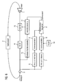
- FIG 3. Another embodiment of the feedback compensator control according to the invention is shown in FIG 3.
- the hearing aid is already for multi-channel internal data processing designed. This means that the input signal, i.e. the Output signal of the microphone 3, through the filters 6 and 7 in Frequency bands is broken down. A feedback compensation takes place in the present case only in the high pass signal. Hearing aid signal processing is in each of the channels 41, 42 are provided. The signals are in front of the receiver 1 of the two channels added.
- FIG. 1 Another embodiment of the present invention is reproduced in FIG.
- the hearing aid not as in the case of FIG. 2 via a feedback compensator 5, but via a gain or compression control 12.
- the reinforcement respectively the compression of the hearing aid can be varied.
- the system distance is too small, be it due to the useful signal or the feedback signal, can amplify the hearing aid be reduced so far that it works again stably.
- the necessary system distance is the same as in the previous ones Examples provided by the comparator 11.
- the entire estimation unit 6 to 11 corresponds to that of the Embodiment according to FIG 2.
- FIG. 5 shows an embodiment of the present invention shown, which is essentially a combination of the Embodiments of Figures 3 and 4 corresponds.
- the intern Two-channel hearing aid is controlled by a gain control 12 in the high-frequency channel of feedback signals freed.
- FIG. 6. Another embodiment is shown in FIG. 6. in the The construction of the hearing device essentially corresponds to that of FIG 2 or from FIG 4. However, the feedback is here in Input signal through a feedback or oscillation detector 13 detected.
- a notch filter controller 14 evaluates the output signal of the oscillation detector 13 and controls a narrowband or notch filter 15. Because there is a hearing aid coupling due to an increase in resonance and makes the whistle noticeable, it can also are largely suppressed by a notch filter 15.
- the Notch filter 15 is for this purpose between the hearing aid signal processing 4 and the handset 1 switched. Used as a control signal the notch filter controller 14 also the system distance from comparator 11.
Landscapes
- Acoustics & Sound (AREA)
- Health & Medical Sciences (AREA)
- Neurosurgery (AREA)
- Otolaryngology (AREA)
- Physics & Mathematics (AREA)
- Engineering & Computer Science (AREA)
- Signal Processing (AREA)
- General Health & Medical Sciences (AREA)
- Amplifiers (AREA)
- Measurement Of Velocity Or Position Using Acoustic Or Ultrasonic Waves (AREA)
- Length Measuring Devices Characterised By Use Of Acoustic Means (AREA)
- Radar Systems Or Details Thereof (AREA)
- Tone Control, Compression And Expansion, Limiting Amplitude (AREA)
- Circuit For Audible Band Transducer (AREA)
Abstract
Description
- FIG 1
- ein Blockschaltbild eines Feedbackkompensationsfilters gemäß dem Stand der Technik;
- FIG 2
- ein Blockschaltbild eines erfindungsgemäßen Feedbackkompensators mit vom Systemabstand geführter Schrittweitensteuerung;
- FIG 3
- ein Blockschaltbild eines erfindungsgemäßen Teilband-Feedbackkompensators mit vom Systemabstand geführter Schrittweitensteuerung;
- FIG 4
- ein Blockschaltbild einer erfindungsgemäßen Verstärkungs- und/oder Kompressionssteuerung auf Basis des Systemabstands;
- FIG 5
- ein Blockschaltbild einer erfindungsgemäßen Verstärkungs- und/oder Kompressionssteuerung auf Basis des Systemabstands bei Mehrkanalgeräten; und
- FIG 6
- ein Blockschaltbild einer erfindungsgemäßen Feedbackunterdrückung durch ein adaptives Notchfilter unter Berücksichtigung des Systemabstands.
Claims (14)
- Vorrichtung zur Rückkopplungskompensation bei Hörgeräten mit
einer Signaleingangseinrichtung (3) zur Aufnahme eines Eingangssignals, das durch eine Rückkopplung beeinflusst ist,
einer Rückkopplungsverminderungseinrichtung (5, 12, 13, 14) zur einstellbaren Reduktion , Kompensation oder Dämpfung der Rückkopplung und
einer Signalausgangseinrichtung (1) zur Ausgabe eines Ausgangssignals mit reduziertem Rückkopplungsanteil,
gekennzeichnet durch
eine Schätzeinrichtung (6 bis 11), die zwischen die Signaleingangseinrichtung (3) und die Rückkopplungsverminderungseinrichtung (5, 12, 13, 14) geschaltet ist und mit der aus dem Eingangssignal ein Schätzwert eines Systemabstandes, der durch den Abstand der Kreisverstärkung des rückgekoppelten Systems zu seiner vorgegebenen Stabilitätsgrenze definiert ist, ermittelbar ist, so dass Parameter der Rückkopplungsverminderungseinrichtung (5, 12, 13, 14) anhand des Schätzwerts steuerbar sind. - Vorrichtung nach Anspruch 1, wobei mit der Schätzeinrichtung (6 bis 11) ein erster Signalanteil und zweiter Signalanteil aus dem Eingangssignal erfassbar, ein Schätzsignal für den zweiten Signalanteil insbesondere mittels eines Modells aus dem ersten Signalanteil erstellbar und der Schätzwert aus dem Unterschied des Schätzsignals und des zweiten Signalanteils ermittelbar ist.
- Vorrichtung nach Anspruch 2, wobei der erste Signalanteil einem hochfrequenten Anteil des Eingangssignals und der zweite Signalanteil einem niederfrequenten Anteil des Eingangssignals entspricht.
- Vorrichtung nach Anspruch 2 oder 3, wobei Merkmale aus den Signalanteilen zur Weiterverarbeitung extrahierbar sind.
- Vorrichtung nach einem der Ansprüche 1 bis 4, wobei die Rückkopplungsverminderungseinrichtung (5, 12, 13, 14) einen Feedbackkompensator (5) umfasst.
- Vorrichtung nach einem der Ansprüche 1 bis 5, wobei die Rückkopplungsverminderungseinrichtung (5, 12, 13, 14) eine Verstärkungs-/Kompressionssteuerung (12) für ein Hörgerät umfasst.
- Vorrichtung nach einem der Ansprüche 1 bis 6, wobei die Rückkopplungsverminderungseinrichtung (5, 12, 13, 14) mindestens einen Oszillationsdetektor (13) und mindestens eine Schmalbandfiltereinrichtung (14) zur Unterdrückung von Schwingungen auf der Grundlage des Schätzwertes aufweist.
- Verfahren zur Rückkopplungskompensation bei Hörgeräten durch
Aufnehmen eines Eingangssignals, das durch eine Rückkopplung beeinflusst ist,
einstellbares Reduzieren, Kompensieren oder Dämpfen der Rückkopplung und
Ausgeben eines Ausgangssignals mit reduziertem Rückkopplungsanteil,
gekennzeichnet durch
Schätzen eines Systemabstands, der durch den Abstand der Kreisverstärkung des rückgekoppelten Systems zu seiner vorgegebenen Stabilitätsgrenze definiert ist, und
Steuern des Reduzierens, Kompensierens oder Dämpfens der Rückkopplung anhand des Schätzwerts. - Verfahren nach Anspruch 8, wobei das Schätzen erfolgt durch die Schritte des Erfassens eines ersten Signalanteils und eines zweiten Signalanteils des Eingangssignals, des Bildens eines Vorhersagesignals für den zweiten Signalanteil aus dem ersten Signalanteil insbesondere mittels eines Modells und des Ermittelns des Schätzwertes aus dem Unterschied von Vorhersagesignal und zweitem Signalanteil.
- Verfahren nach Anspruch 9, wobei der erste Signalanteil einem hochfrequenten Anteil des Eingangssignals und der zweite Signalanteil einem niederfrequenten Anteil des Eingangssignals entspricht.
- Verfahren nach Anspruch 9 oder 10, wobei nach dem Erfassen des ersten und zweiten Signalanteils ein Extrahieren von Signalmerkmalen aus den Signalanteilen zur Weiterverarbeitung stattfindet.
- Verfahren nach einem der Ansprüche 8 bis 11, wobei das Reduzieren oder Dämpfen des Rückkopplungssignals durch adaptive Feedbackkompensation erfolgt.
- Verfahren nach einem der Ansprüche 8 bis 11, wobei das Reduzieren oder Dämpfen des Rückkopplungssignals durch Steuerung der Verstärkung/Kompression eines Hörgeräts erfolgt.
- Verfahren nach einem der Ansprüche 8 bis 11, wobei das Reduzieren oder Dämpfen des Rückkopplungssignals durch Detektieren einer Schwingung und schmalbandiges Ausfiltern dieser Schwingung erfolgt.
Applications Claiming Priority (2)
| Application Number | Priority Date | Filing Date | Title |
|---|---|---|---|
| DE10244184A DE10244184B3 (de) | 2002-09-23 | 2002-09-23 | Feedbackkompensation für Hörgeräte mit Systemabstandsschätzung |
| DE10244184 | 2002-09-23 |
Publications (3)
| Publication Number | Publication Date |
|---|---|
| EP1401242A2 true EP1401242A2 (de) | 2004-03-24 |
| EP1401242A3 EP1401242A3 (de) | 2008-02-20 |
| EP1401242B1 EP1401242B1 (de) | 2008-12-03 |
Family
ID=31896304
Family Applications (1)
| Application Number | Title | Priority Date | Filing Date |
|---|---|---|---|
| EP03021037A Expired - Lifetime EP1401242B1 (de) | 2002-09-23 | 2003-09-17 | Feedbackkompensation für Hörgeräte mit Systemabstandsschätzung |
Country Status (5)
| Country | Link |
|---|---|
| US (1) | US20040109578A1 (de) |
| EP (1) | EP1401242B1 (de) |
| AT (1) | ATE416591T1 (de) |
| DE (2) | DE10244184B3 (de) |
| DK (1) | DK1401242T3 (de) |
Cited By (4)
| Publication number | Priority date | Publication date | Assignee | Title |
|---|---|---|---|---|
| EP1858289A1 (de) | 2006-05-19 | 2007-11-21 | Siemens Audiologische Technik GmbH | Hörvorrichtung mit Rückkopplungsdetektion und entsprechendes Verfahren |
| US8280088B2 (en) | 2006-05-19 | 2012-10-02 | Siemens Audiologische Technik Gmbh | Hearing apparatus with feedback detection and corresponding method |
| EP2360945A3 (de) * | 2010-01-29 | 2013-07-10 | Siemens Medical Instruments Pte. Ltd. | Hörgerät mit Frequenzverschiebung und zugehöriges Verfahren |
| CN111629313A (zh) * | 2019-02-27 | 2020-09-04 | 奥迪康有限公司 | 包括环路增益限制器的听力装置 |
Families Citing this family (11)
| Publication number | Priority date | Publication date | Assignee | Title |
|---|---|---|---|---|
| CA2357200C (en) * | 2001-09-07 | 2010-05-04 | Dspfactory Ltd. | Listening device |
| US6917471B2 (en) * | 2003-01-24 | 2005-07-12 | Sumitomo Electric Industries, Ltd. | Diffraction grating element |
| US7127076B2 (en) * | 2003-03-03 | 2006-10-24 | Phonak Ag | Method for manufacturing acoustical devices and for reducing especially wind disturbances |
| DE102004053776B4 (de) * | 2004-11-08 | 2007-10-31 | Siemens Audiologische Technik Gmbh | Verfahren zur Verstärkung eines Akustiksignals und entsprechendes Akustiksystem |
| DE102006020832B4 (de) † | 2006-05-04 | 2016-10-27 | Sivantos Gmbh | Verfahren zum Unterdrücken von Rückkopplungen bei Hörvorrichtungen |
| US7925307B2 (en) * | 2006-10-31 | 2011-04-12 | Palm, Inc. | Audio output using multiple speakers |
| DE102009012162A1 (de) * | 2009-03-06 | 2010-09-09 | Siemens Medical Instruments Pte. Ltd. | Verfahren zum Betrieb einer Hörvorrichtung und Hörvorrichtung mit einer Rückkopplungsunterdrückung |
| DE102009018812B4 (de) * | 2009-04-24 | 2015-05-28 | Siemens Medical Instruments Pte. Ltd. | Verfahren zum Betrieb einer Hörvorrichtung und Hörvorrichtung mit einer Frequenzweiche |
| WO2010040863A2 (en) | 2010-01-15 | 2010-04-15 | Phonak Ag | A method for operating a hearing device as well as a hearing device |
| KR102007509B1 (ko) * | 2013-05-06 | 2019-08-06 | 삼성전자주식회사 | 고막과 청각 장치간의 거리를 측정하는 청각 장치 및 방법 |
| DE102014218672B3 (de) * | 2014-09-17 | 2016-03-10 | Sivantos Pte. Ltd. | Verfahren und Vorrichtung zur Rückkopplungsunterdrückung |
Family Cites Families (13)
| Publication number | Priority date | Publication date | Assignee | Title |
|---|---|---|---|---|
| ATE69132T1 (de) * | 1987-02-17 | 1991-11-15 | Siemens Ag | Schaltungsanordnung zum erkennen von schwingungen. |
| FR2635680B1 (fr) * | 1988-08-30 | 1997-12-26 | Belone Electronics Corp | Prothese auditive |
| US5091952A (en) * | 1988-11-10 | 1992-02-25 | Wisconsin Alumni Research Foundation | Feedback suppression in digital signal processing hearing aids |
| DK169958B1 (da) * | 1992-10-20 | 1995-04-10 | Gn Danavox As | Høreapparat med kompensation for akustisk tilbagekobling |
| EP0585976A3 (en) * | 1993-11-10 | 1994-06-01 | Phonak Ag | Hearing aid with cancellation of acoustic feedback |
| US6072884A (en) * | 1997-11-18 | 2000-06-06 | Audiologic Hearing Systems Lp | Feedback cancellation apparatus and methods |
| US6498858B2 (en) * | 1997-11-18 | 2002-12-24 | Gn Resound A/S | Feedback cancellation improvements |
| US6219427B1 (en) * | 1997-11-18 | 2001-04-17 | Gn Resound As | Feedback cancellation improvements |
| DK1203509T3 (da) * | 1999-07-19 | 2007-01-02 | Oticon As | Tilbagekoblingsannullering med anvendelse af båndbreddedetektering |
| US6434247B1 (en) * | 1999-07-30 | 2002-08-13 | Gn Resound A/S | Feedback cancellation apparatus and methods utilizing adaptive reference filter mechanisms |
| US6480610B1 (en) * | 1999-09-21 | 2002-11-12 | Sonic Innovations, Inc. | Subband acoustic feedback cancellation in hearing aids |
| US6754356B1 (en) * | 2000-10-06 | 2004-06-22 | Gn Resound As | Two-stage adaptive feedback cancellation scheme for hearing instruments |
| US6831986B2 (en) * | 2000-12-21 | 2004-12-14 | Gn Resound A/S | Feedback cancellation in a hearing aid with reduced sensitivity to low-frequency tonal inputs |
-
2002
- 2002-09-23 DE DE10244184A patent/DE10244184B3/de not_active Expired - Fee Related
-
2003
- 2003-09-17 EP EP03021037A patent/EP1401242B1/de not_active Expired - Lifetime
- 2003-09-17 DE DE50310852T patent/DE50310852D1/de not_active Expired - Lifetime
- 2003-09-17 DK DK03021037T patent/DK1401242T3/da active
- 2003-09-17 AT AT03021037T patent/ATE416591T1/de not_active IP Right Cessation
- 2003-09-23 US US10/668,855 patent/US20040109578A1/en not_active Abandoned
Cited By (6)
| Publication number | Priority date | Publication date | Assignee | Title |
|---|---|---|---|---|
| EP1858289A1 (de) | 2006-05-19 | 2007-11-21 | Siemens Audiologische Technik GmbH | Hörvorrichtung mit Rückkopplungsdetektion und entsprechendes Verfahren |
| US8280088B2 (en) | 2006-05-19 | 2012-10-02 | Siemens Audiologische Technik Gmbh | Hearing apparatus with feedback detection and corresponding method |
| EP2360945A3 (de) * | 2010-01-29 | 2013-07-10 | Siemens Medical Instruments Pte. Ltd. | Hörgerät mit Frequenzverschiebung und zugehöriges Verfahren |
| US8538053B2 (en) | 2010-01-29 | 2013-09-17 | Siemens Medical Instruments Pte. Ltd. | Hearing device with frequency shifting and associated method |
| CN111629313A (zh) * | 2019-02-27 | 2020-09-04 | 奥迪康有限公司 | 包括环路增益限制器的听力装置 |
| CN111629313B (zh) * | 2019-02-27 | 2023-12-01 | 奥迪康有限公司 | 包括环路增益限制器的听力装置 |
Also Published As
| Publication number | Publication date |
|---|---|
| US20040109578A1 (en) | 2004-06-10 |
| DK1401242T3 (da) | 2009-04-06 |
| EP1401242A3 (de) | 2008-02-20 |
| EP1401242B1 (de) | 2008-12-03 |
| ATE416591T1 (de) | 2008-12-15 |
| DE10244184B3 (de) | 2004-04-15 |
| DE50310852D1 (de) | 2009-01-15 |
Similar Documents
| Publication | Publication Date | Title |
|---|---|---|
| DE60028779T2 (de) | Rückkopplungsanullierung mit niederfrequenzeingang | |
| DE10244184B3 (de) | Feedbackkompensation für Hörgeräte mit Systemabstandsschätzung | |
| DE69814142T2 (de) | Vorrichtung und verfahren zur rückkopplungsunterdrückung | |
| EP1239700B2 (de) | Verfahren zum Betrieb eines Hörhilfegerätes oder Hörgerätesystem sowie Hörhilfegerät oder Hörgerätesystem | |
| DE69033177T2 (de) | Hörgerät mit Kompensation der akustischen Rückkopplung | |
| CH694543A5 (de) | Verfahren zur Rückkopplungserkennung in einem Hörgerät und Hörgerät zum Ausführen dieses Verfahrens. | |
| DE102006047965A1 (de) | Hörhilfsgerät mit einer Okklusionsreduktionseinrichtung und Verfahren zur Okklusionsreduktion | |
| EP3222057A1 (de) | Verfahren und vorrichtung zum schnellen erkennen der eigenen stimme | |
| EP3068146B1 (de) | Verfahren zum betrieb eines hörgeräts sowie hörgerät | |
| DE102015216822B4 (de) | Verfahren zur Unterdrückung einer Rückkopplung in einem Hörgerät | |
| EP3598778B1 (de) | Verfahren zum betrieb eines hörgeräts sowie hörgerät zur detektion der eigenstimme anhand eines individuellen schwellwerts | |
| EP2023669A2 (de) | Verfahren zum Betrieb eines Hörgerätesystems und Hörgerätesystem | |
| EP1912471A2 (de) | Verarbeitung eines Eingangssignals in einer Hörhilfe | |
| DE10357800B3 (de) | Hörgerät mit Störgeräuschunterdrückung und entsprechendes Störgeräuschunterdrückungsverfahren | |
| EP1523220A2 (de) | Hörhilfevorrichtung zum automatischen Schalten in einen Telefonbetrieb und entsprechendes Verfahren | |
| EP2360945B1 (de) | Hörgerät mit Frequenzverschiebung und zugehöriges Verfahren | |
| EP1152527A1 (de) | Vorrichtung und Verfahren zum geräuschabhängigen Anpassen eines akustischen Nutzsignals | |
| DE10242700B4 (de) | Rückkopplungskompensator in einem akustischen Verstärkungssystem, Hörhilfsgerät, Verfahren zur Rückkopplungskompensation und Anwendung des Verfahrens in einem Hörhilfsgerät | |
| EP2981099A2 (de) | Verfahren und vorrichtung zur rückkopplungsunterdrückung | |
| EP1648197B2 (de) | Verfahren und Vorrichtung zur Reduktion von Rückkopplungen bei einem Akustiksystem | |
| EP1858289A1 (de) | Hörvorrichtung mit Rückkopplungsdetektion und entsprechendes Verfahren | |
| DE102010025918B4 (de) | Verfahren zum Betrieb eines Hörgeräts und Hörgerät mit variabler Frequenzverschiebung | |
| DE10310580A1 (de) | Vorrichtung und Verfahren zur Adaption von Hörgerätemikrofonen | |
| DE102016221692B3 (de) | Verfahren zum Betrieb eines Hörgeräts | |
| DE102005008318B4 (de) | Hörhilfegerät mit benutzergesteuerter Einmessautomatik |
Legal Events
| Date | Code | Title | Description |
|---|---|---|---|
| PUAI | Public reference made under article 153(3) epc to a published international application that has entered the european phase |
Free format text: ORIGINAL CODE: 0009012 |
|
| AK | Designated contracting states |
Kind code of ref document: A2 Designated state(s): AT BE BG CH CY CZ DE DK EE ES FI FR GB GR HU IE IT LI LU MC NL PT RO SE SI SK TR |
|
| AX | Request for extension of the european patent |
Extension state: AL LT LV MK |
|
| PUAL | Search report despatched |
Free format text: ORIGINAL CODE: 0009013 |
|
| AK | Designated contracting states |
Kind code of ref document: A3 Designated state(s): AT BE BG CH CY CZ DE DK EE ES FI FR GB GR HU IE IT LI LU MC NL PT RO SE SI SK TR |
|
| AX | Request for extension of the european patent |
Extension state: AL LT LV MK |
|
| 17P | Request for examination filed |
Effective date: 20080204 |
|
| GRAP | Despatch of communication of intention to grant a patent |
Free format text: ORIGINAL CODE: EPIDOSNIGR1 |
|
| AKX | Designation fees paid |
Designated state(s): AT BE BG CH CY CZ DE DK EE ES FI FR GB GR HU IE IT LI LU MC NL PT RO SE SI SK TR |
|
| GRAS | Grant fee paid |
Free format text: ORIGINAL CODE: EPIDOSNIGR3 |
|
| GRAS | Grant fee paid |
Free format text: ORIGINAL CODE: EPIDOSNIGR3 |
|
| GRAA | (expected) grant |
Free format text: ORIGINAL CODE: 0009210 |
|
| AK | Designated contracting states |
Kind code of ref document: B1 Designated state(s): AT BE BG CH CY CZ DE DK EE ES FI FR GB GR HU IE IT LI LU MC NL PT RO SE SI SK TR |
|
| REG | Reference to a national code |
Ref country code: GB Ref legal event code: FG4D Free format text: NOT ENGLISH |
|
| REG | Reference to a national code |
Ref country code: CH Ref legal event code: EP Ref country code: CH Ref legal event code: NV Representative=s name: SIEMENS SCHWEIZ AG |
|
| REG | Reference to a national code |
Ref country code: IE Ref legal event code: FG4D Free format text: LANGUAGE OF EP DOCUMENT: GERMAN |
|
| REF | Corresponds to: |
Ref document number: 50310852 Country of ref document: DE Date of ref document: 20090115 Kind code of ref document: P |
|
| REG | Reference to a national code |
Ref country code: CH Ref legal event code: PCAR Free format text: SIEMENS SCHWEIZ AG;INTELLECTUAL PROPERTY FREILAGERSTRASSE 40;8047 ZUERICH (CH) |
|
| REG | Reference to a national code |
Ref country code: DK Ref legal event code: T3 |
|
| PG25 | Lapsed in a contracting state [announced via postgrant information from national office to epo] |
Ref country code: ES Free format text: LAPSE BECAUSE OF FAILURE TO SUBMIT A TRANSLATION OF THE DESCRIPTION OR TO PAY THE FEE WITHIN THE PRESCRIBED TIME-LIMIT Effective date: 20090314 |
|
| NLV1 | Nl: lapsed or annulled due to failure to fulfill the requirements of art. 29p and 29m of the patents act | ||
| PG25 | Lapsed in a contracting state [announced via postgrant information from national office to epo] |
Ref country code: SI Free format text: LAPSE BECAUSE OF FAILURE TO SUBMIT A TRANSLATION OF THE DESCRIPTION OR TO PAY THE FEE WITHIN THE PRESCRIBED TIME-LIMIT Effective date: 20081203 Ref country code: NL Free format text: LAPSE BECAUSE OF FAILURE TO SUBMIT A TRANSLATION OF THE DESCRIPTION OR TO PAY THE FEE WITHIN THE PRESCRIBED TIME-LIMIT Effective date: 20081203 Ref country code: FI Free format text: LAPSE BECAUSE OF FAILURE TO SUBMIT A TRANSLATION OF THE DESCRIPTION OR TO PAY THE FEE WITHIN THE PRESCRIBED TIME-LIMIT Effective date: 20081203 |
|
| REG | Reference to a national code |
Ref country code: IE Ref legal event code: FD4D |
|
| PG25 | Lapsed in a contracting state [announced via postgrant information from national office to epo] |
Ref country code: EE Free format text: LAPSE BECAUSE OF FAILURE TO SUBMIT A TRANSLATION OF THE DESCRIPTION OR TO PAY THE FEE WITHIN THE PRESCRIBED TIME-LIMIT Effective date: 20081203 Ref country code: BG Free format text: LAPSE BECAUSE OF FAILURE TO SUBMIT A TRANSLATION OF THE DESCRIPTION OR TO PAY THE FEE WITHIN THE PRESCRIBED TIME-LIMIT Effective date: 20090303 Ref country code: IE Free format text: LAPSE BECAUSE OF FAILURE TO SUBMIT A TRANSLATION OF THE DESCRIPTION OR TO PAY THE FEE WITHIN THE PRESCRIBED TIME-LIMIT Effective date: 20081203 Ref country code: RO Free format text: LAPSE BECAUSE OF FAILURE TO SUBMIT A TRANSLATION OF THE DESCRIPTION OR TO PAY THE FEE WITHIN THE PRESCRIBED TIME-LIMIT Effective date: 20081203 |
|
| PG25 | Lapsed in a contracting state [announced via postgrant information from national office to epo] |
Ref country code: SE Free format text: LAPSE BECAUSE OF FAILURE TO SUBMIT A TRANSLATION OF THE DESCRIPTION OR TO PAY THE FEE WITHIN THE PRESCRIBED TIME-LIMIT Effective date: 20090303 Ref country code: CZ Free format text: LAPSE BECAUSE OF FAILURE TO SUBMIT A TRANSLATION OF THE DESCRIPTION OR TO PAY THE FEE WITHIN THE PRESCRIBED TIME-LIMIT Effective date: 20081203 Ref country code: PT Free format text: LAPSE BECAUSE OF FAILURE TO SUBMIT A TRANSLATION OF THE DESCRIPTION OR TO PAY THE FEE WITHIN THE PRESCRIBED TIME-LIMIT Effective date: 20090504 |
|
| PG25 | Lapsed in a contracting state [announced via postgrant information from national office to epo] |
Ref country code: SK Free format text: LAPSE BECAUSE OF FAILURE TO SUBMIT A TRANSLATION OF THE DESCRIPTION OR TO PAY THE FEE WITHIN THE PRESCRIBED TIME-LIMIT Effective date: 20081203 |
|
| PLBE | No opposition filed within time limit |
Free format text: ORIGINAL CODE: 0009261 |
|
| STAA | Information on the status of an ep patent application or granted ep patent |
Free format text: STATUS: NO OPPOSITION FILED WITHIN TIME LIMIT |
|
| 26N | No opposition filed |
Effective date: 20090904 |
|
| BERE | Be: lapsed |
Owner name: SIEMENS AUDIOLOGISCHE TECHNIK G.M.B.H. Effective date: 20090930 |
|
| PG25 | Lapsed in a contracting state [announced via postgrant information from national office to epo] |
Ref country code: MC Free format text: LAPSE BECAUSE OF NON-PAYMENT OF DUE FEES Effective date: 20090930 |
|
| PG25 | Lapsed in a contracting state [announced via postgrant information from national office to epo] |
Ref country code: BE Free format text: LAPSE BECAUSE OF NON-PAYMENT OF DUE FEES Effective date: 20090930 |
|
| PG25 | Lapsed in a contracting state [announced via postgrant information from national office to epo] |
Ref country code: GR Free format text: LAPSE BECAUSE OF FAILURE TO SUBMIT A TRANSLATION OF THE DESCRIPTION OR TO PAY THE FEE WITHIN THE PRESCRIBED TIME-LIMIT Effective date: 20090304 |
|
| PG25 | Lapsed in a contracting state [announced via postgrant information from national office to epo] |
Ref country code: AT Free format text: LAPSE BECAUSE OF NON-PAYMENT OF DUE FEES Effective date: 20090917 |
|
| PGFP | Annual fee paid to national office [announced via postgrant information from national office to epo] |
Ref country code: DE Payment date: 20101119 Year of fee payment: 8 |
|
| PG25 | Lapsed in a contracting state [announced via postgrant information from national office to epo] |
Ref country code: IT Free format text: LAPSE BECAUSE OF FAILURE TO SUBMIT A TRANSLATION OF THE DESCRIPTION OR TO PAY THE FEE WITHIN THE PRESCRIBED TIME-LIMIT Effective date: 20081203 |
|
| PG25 | Lapsed in a contracting state [announced via postgrant information from national office to epo] |
Ref country code: LU Free format text: LAPSE BECAUSE OF NON-PAYMENT OF DUE FEES Effective date: 20090917 |
|
| PG25 | Lapsed in a contracting state [announced via postgrant information from national office to epo] |
Ref country code: HU Free format text: LAPSE BECAUSE OF FAILURE TO SUBMIT A TRANSLATION OF THE DESCRIPTION OR TO PAY THE FEE WITHIN THE PRESCRIBED TIME-LIMIT Effective date: 20090604 |
|
| PG25 | Lapsed in a contracting state [announced via postgrant information from national office to epo] |
Ref country code: TR Free format text: LAPSE BECAUSE OF FAILURE TO SUBMIT A TRANSLATION OF THE DESCRIPTION OR TO PAY THE FEE WITHIN THE PRESCRIBED TIME-LIMIT Effective date: 20081203 |
|
| PG25 | Lapsed in a contracting state [announced via postgrant information from national office to epo] |
Ref country code: CY Free format text: LAPSE BECAUSE OF FAILURE TO SUBMIT A TRANSLATION OF THE DESCRIPTION OR TO PAY THE FEE WITHIN THE PRESCRIBED TIME-LIMIT Effective date: 20081203 |
|
| PGFP | Annual fee paid to national office [announced via postgrant information from national office to epo] |
Ref country code: DK Payment date: 20110926 Year of fee payment: 9 |
|
| PGFP | Annual fee paid to national office [announced via postgrant information from national office to epo] |
Ref country code: GB Payment date: 20110915 Year of fee payment: 9 Ref country code: FR Payment date: 20111005 Year of fee payment: 9 |
|
| PGFP | Annual fee paid to national office [announced via postgrant information from national office to epo] |
Ref country code: CH Payment date: 20111213 Year of fee payment: 9 |
|
| REG | Reference to a national code |
Ref country code: CH Ref legal event code: PL |
|
| GBPC | Gb: european patent ceased through non-payment of renewal fee |
Effective date: 20120917 |
|
| REG | Reference to a national code |
Ref country code: DK Ref legal event code: EBP |
|
| REG | Reference to a national code |
Ref country code: FR Ref legal event code: ST Effective date: 20130531 |
|
| PG25 | Lapsed in a contracting state [announced via postgrant information from national office to epo] |
Ref country code: DE Free format text: LAPSE BECAUSE OF NON-PAYMENT OF DUE FEES Effective date: 20130403 Ref country code: GB Free format text: LAPSE BECAUSE OF NON-PAYMENT OF DUE FEES Effective date: 20120917 Ref country code: LI Free format text: LAPSE BECAUSE OF NON-PAYMENT OF DUE FEES Effective date: 20120930 Ref country code: CH Free format text: LAPSE BECAUSE OF NON-PAYMENT OF DUE FEES Effective date: 20120930 |
|
| PG25 | Lapsed in a contracting state [announced via postgrant information from national office to epo] |
Ref country code: FR Free format text: LAPSE BECAUSE OF NON-PAYMENT OF DUE FEES Effective date: 20121001 |
|
| REG | Reference to a national code |
Ref country code: DE Ref legal event code: R119 Ref document number: 50310852 Country of ref document: DE Effective date: 20130403 |
|
| PG25 | Lapsed in a contracting state [announced via postgrant information from national office to epo] |
Ref country code: DK Free format text: LAPSE BECAUSE OF NON-PAYMENT OF DUE FEES Effective date: 20121001 |