EP1401254B1 - Ständer für absetzbaren ladebehälter und verfahren zum absetzen des ladebehälters von einem fahrzeug - Google Patents
Ständer für absetzbaren ladebehälter und verfahren zum absetzen des ladebehälters von einem fahrzeug Download PDFInfo
- Publication number
- EP1401254B1 EP1401254B1 EP02743174A EP02743174A EP1401254B1 EP 1401254 B1 EP1401254 B1 EP 1401254B1 EP 02743174 A EP02743174 A EP 02743174A EP 02743174 A EP02743174 A EP 02743174A EP 1401254 B1 EP1401254 B1 EP 1401254B1
- Authority
- EP
- European Patent Office
- Prior art keywords
- box
- vehicle
- cargo box
- stand
- attachment member
- Prior art date
- Legal status (The legal status is an assumption and is not a legal conclusion. Google has not performed a legal analysis and makes no representation as to the accuracy of the status listed.)
- Expired - Lifetime
Links
- 238000000034 method Methods 0.000 title claims description 8
- 238000010276 construction Methods 0.000 description 3
- 238000011161 development Methods 0.000 description 2
- 230000018109 developmental process Effects 0.000 description 2
- 239000002184 metal Substances 0.000 description 2
- 241000270730 Alligator mississippiensis Species 0.000 description 1
- 230000001133 acceleration Effects 0.000 description 1
- 230000009286 beneficial effect Effects 0.000 description 1
- 230000001419 dependent effect Effects 0.000 description 1
- 239000000463 material Substances 0.000 description 1
- 238000012986 modification Methods 0.000 description 1
- 230000004048 modification Effects 0.000 description 1
- 239000002689 soil Substances 0.000 description 1
Images



Classifications
-
- B—PERFORMING OPERATIONS; TRANSPORTING
- B60—VEHICLES IN GENERAL
- B60P—VEHICLES ADAPTED FOR LOAD TRANSPORTATION OR TO TRANSPORT, TO CARRY, OR TO COMPRISE SPECIAL LOADS OR OBJECTS
- B60P1/00—Vehicles predominantly for transporting loads and modified to facilitate loading, consolidating the load, or unloading
- B60P1/04—Vehicles predominantly for transporting loads and modified to facilitate loading, consolidating the load, or unloading with a tipping movement of load-transporting element
- B60P1/28—Tipping body constructions
- B60P1/283—Elements of tipping devices
-
- B—PERFORMING OPERATIONS; TRANSPORTING
- B60—VEHICLES IN GENERAL
- B60P—VEHICLES ADAPTED FOR LOAD TRANSPORTATION OR TO TRANSPORT, TO CARRY, OR TO COMPRISE SPECIAL LOADS OR OBJECTS
- B60P1/00—Vehicles predominantly for transporting loads and modified to facilitate loading, consolidating the load, or unloading
- B60P1/04—Vehicles predominantly for transporting loads and modified to facilitate loading, consolidating the load, or unloading with a tipping movement of load-transporting element
Definitions
- the present invention relates to a utility transport tractor that combines with an agricultural tractor the capability to transport materials and in particular to a stand for supporting a removable vehicle cargo box and method for removing and remounting the cargo box.
- Agricultural tractors are designed primarily to supply power to agricultural implements and to produce a continuous draft force in the direction of travel to enable soil engaging implements to perform their intended functions.
- Agricultural tractors must be designed with sufficient downward force acting on the drive wheels to produce the desired draft force. Often this results in a vehicle having drive wheels that are larger than the non-drive wheels to accommodate the large downward force on the drive wheels.
- Agricultural tractors differ from cargo carrying vehicles such as trucks in that trucks do not need to produce a continuous draft load. A truck only needs to produce a draft load when pulling a load during periods of acceleration and deceleration.
- An agricultural tractor designed primarily to produce a draft load, has limited, if any, ability to carry cargo.
- a farmer must use a truck or a wagon hitched to a tractor to haul cargo.
- Other cargo hauling utility vehicles such as a John Deere Gator® utility vehicle can also be used.
- Trucks and utility vehicles have shortcomings when working with agricultural implements. They do not have the tractive ability of an agricultural tractor and are generally not equipped with a three-point hitch. In small farm operations where it is not practical to buy several pieces of equipment, it is beneficial to have a utility transport tractor that combines the typical features of an agricultural tractor with the capability to carry cargo.
- Past attempts to combine tractors and trucks have focused on adding a three-point hitch to a truck. These products suffer from poor performance in pulling an implement and often lack visibility typical of a tractor, especially visibility of the hitch.
- the utility transport tractors have been developed that modify an agricultural tractor to add a cargo box while maintaining the typical features of an agricultural tractor that provide for the continuous draft force and include a three-point hitch for pulling an implement. At times, however, an operator will desire to operate the vehicle without the cargo box. While a cargo box can be removably mounted to the tractor, a convenient means of handling the cargo box during removal and mounting and for storage of the cargo box after removal is still needed.
- US 3 623 621 discloses a stand for a removable cargo box according to the preamble of claim 1.
- the present invention provides a cargo box stand to mount the cargo box on and removing the cargo box from a vehicle and a method for using the stand.
- a preferred embodiment of the stand consists of separate left and right legs that are left and right mirror images of one another.
- Each leg includes a support member having a base to hold the support member in an upright position.
- a cargo box attachment member is pivotally mounted to the support member for rotation about a pivot and is adapted to attach to the cargo box.
- a vehicle attachment member is also mounted to the support member and is adapted to be attached to the vehicle, in this case a vehicle, to hold the leg in place relative to the vehicle while removing and remounting the cargo box.
- a latch holds the cargo box attachment member in a fixed rotational position relative to the support member.
- Removal of the dumping cargo box in its lowered position begins by first attaching the legs to the respective left and right frame rails of the cargo box by the cargo box attachment members and subsequently attaching the legs to the vehicle frame by the vehicle attachment members respectively.
- the cargo box is then detached from the vehicle frame at the cargo box pivot point after which the box is raised to a tilted position by using the lift cylinders normally used for raising the cargo box.
- the pivot box reaches an inclined position necessary to clear various components on the vehicle, the legs lock the box attachment member to the support member with the box in the inclined position.
- the lift cylinders are subsequently uncoupled from the cargo box and the vehicle attachment member is uncoupled from the vehicle.
- the cargo box is supported solely on the legs and the vehicle can be moved forward away from the cargo box.
- the cargo box is later remounted to the vehicle by reversing the above steps.
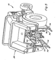
- the utility transport tractor with which the stand of the present invention is used is shown and designated generally at 10.
- the tractor 10 has a front hood 12 covering an engine, rear drive wheels 14 on a rear axle 15 and front wheels 16 on an axle 17, all part of a tractor chassis 19.
- the front wheels 16 can be driven or non-driven.
- An operator's station 18 is located forward of the rear wheels and includes a center operator's seat 20 and left and right passenger seats 22, 24.
- a cargo box 26 is located rearward of the operator's station 18 and generally above the rear axle 15 and rear wheels 14.
- a three-point hitch 28 (Fig. 2) is mounted behind the rear axle 15 and beneath the cargo box 26.
- the three-point hitch 28 includes a pair of lower draft links 30 and an upper link 32 in a conventional manner for a three-point hitch.
- the cargo box 26 has a generally horizontal floor 34, an upright front wall 36, left and right side walls 38 and a tailgate 40.
- the cargo box side walls 38 form wheel wells for the rear wheels 14 with a portion of the cargo box 26 being disposed above each rear wheel 14.
- Fenders 43 are attached to the tractor chassis 19 and are shaped to fit partially within the wheel wells.
- the cargo box 26 has a pair of rails 108 made of metal.
- the floor 34 and the bottom portions of the side-walls are also made of metal.
- the upper portions of the side walls, the front wall 36 and the tailgate 40 are molded of plastic. The plastic panels resist dents and are molded with color to avoid the need to be painted.
- the tractor 10 has a pair of frame rails 50 extending lengthwise of the tractor in the rear portion of the tractor.
- the frame rails 50 include rear pivot mounting bosses 52 adjacent to the rear of the frame rails 50.
- Hydraulic lift cylinders 54 are coupled to the frame rails 50 through mounting brackets 56 and 58.
- the lift cylinders 54 extend to raise the cargo box 26 from its horizontal position to an inclined dump position in a well known manner.
- the lift cylinders 54 are attached to mounting bosses 60 fastened to the cargo box rails 108.
- the cargo box 26 carries pivot mounting bosses 62 with box pivots 63 to pivotally mount the cargo box 26 to the pivot mounting bosses 52 of the tractor frame.
- Removable pivot pins 64 are used to attach the cargo box 26 at the pivotal mount. Similar pivot pins (not shown) are used to attach the lift cylinders 54 to the cargo box 26.
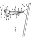
- the right hand leg of the bed stand is shown in Figure 4 and designated generally as 70.
- the leg 70 has an support member 72 coupled to a base 74 to hold the support member 72 in an upright orientation.
- the support member 72 is of a two piece construction, having a lower portion 76 and an upper portion 78 coupled together by a bolt (not shown) extending through aligned apertures 80 and 82. The two piece construction enables the height of the support member 72 to be adjusted.
- a cargo box attachment member 84 is pivotally mounted to the upright support member 72 about a pivot pin 86 at the upper end of the support member 72.
- An upper portion 88 of the box attachment member 84 is shaped as an open "C-shaped" channel that receives the frame rail 108 of the cargo box 26 as described below.
- a pair of pins 90 are inserted vertically through the "C-shaped" proportion 88 and through the cargo box rails to couple the cargo box attachment member 84 to the cargo box rails 108.
- the leg 70 also includes a vehicle attachment member 92 fastened to the support member 72 by the pivot pin 86 and extending outward to a distal end 94.
- the distal end 94 has an aperture 96 through which the vehicle attachment member 92 is attached to the tractor 10 by a pin or bolt (not shown) extending through the aperture 96 and through the aperture 98 at the rear of the tractor frame rails 50.
- a two piece brace 100 extends from the distal end 94 of the vehicle attachment member 92 and downward to the upright support member 72 to provide additional stability to the leg 70 when mounting and removing the cargo box 26 to and from the tractor 10.
- the brace 100 is also of a two piece construction to enable the length of the brace 100 to be adjusted.
- the apertures 102 in the lower piece of the brace are slightly elongated to assist in adjusting the length of the brace 100.
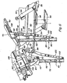
- a spring biased latch pin 110 is carried by the box attachment member 84 and is biased against a latch plate 112.
- the latch plate 112 has an slot 114 at one end thereof. As the cargo box 26 is raised to an inclined dump position, the pin 110 slides across the surface of the latch plate 112 until it reaches the slot 114 and then extends through the slot 114 in the latch plate 112.
- the floor 34 of the cargo box 26 has a fixed front portion 104 and a rotable rear portion 106.
- the rear portion 106 rotates about a laterally extending pivot axis and can be tilted forward and upward as shown in Figure 2.
- the left and right legs 70 are moved into position and coupled to the cargo box rails 108 by the pins 90.
- the vehicle attachment members 92 are then coupled to the two frame rails 50 of the tractor to secure the legs 70 to the tractor.
- the cargo box pivot pins 64 are removed so that the cargo box is only coupled to the tractor through the lift cylinders 54.
- the cylinders 54 are then extended to raise the cargo box 26 to the inclined position shown in Figure 5 until the latch pins 110 reach the slots 114 and extend through the slots 114.
- the cylinders 54 are then slightly retracted until the pins 110 rest on the ends of the slots 114.
- the load acting through the attachments of the lift cylinders 54 is thus relieved, enabling the cylinder attachment pins to be removed more easily.
- the cylinders 54 are then uncoupled from the cargo box 26. This results in the cargo box 26 being completely uncoupled from the tractor 10.
- the vehicle attachment members 92 are then uncoupled from the tractor frame.
- the tractor 10 can be moved forward, away from the cargo box 26 and the stand 70, leaving the cargo box 26 supported on the stand 70 for later remounting to the tractor 10.
- the cargo box 26 is remounted to the tractor 10 by reversing the above steps.
- Storing the cargo box in an inclined position helps to ensure that the cargo box is free from any cargo before it is stored on the stand and prevents filling the cargo box with cargo prior to remounting the cargo box on the tractor. This minimizes the weight carried by the cargo box stand.
Landscapes
- Engineering & Computer Science (AREA)
- Transportation (AREA)
- Mechanical Engineering (AREA)
- Body Structure For Vehicles (AREA)
- Fittings On The Vehicle Exterior For Carrying Loads, And Devices For Holding Or Mounting Articles (AREA)
- Vehicle Cleaning, Maintenance, Repair, Refitting, And Outriggers (AREA)
- Loading Or Unloading Of Vehicles (AREA)
Claims (6)
- Ständer für absetzbare Fahrzeugladebehälter (26) enthaltend:ein Tragteil (72), welches eine Basis (74) hat, um das Tragteil (72) in einer aufrechten Position zu halten, undein Ladebehälterbefestigungselement (84), welches zur Verdrehung um eine Drehachse (86) verdrehbar an dem Tragteil (72) montiert ist und welches angepasst ist, um an einen Ladebehälter (26) angebracht zu werden,
dadurch gekennzeichnet, dass der Ständer des Weiteren enthält:ein Fahrzeugbefestigungsteil (92), welches an dem Tragteil (72) montierbar und angepasst ist, um an dem Fahrzeug (10) befestigt zu werden, damit während der Demontage des Ladebehälters (26) von dem Fahrzeug (10) den Ständer (70) relativ zum Fahrzeug (10) in der richtigen Lage gehalten wird, undeiner Rastvorrichtung (110-114), um das Ladebehälterbefestigungselement (84) in einer festen Drehposition relativ zum Tragteil (72) zu halten. - Ständer, wie durch Anspruch 1 definiert, enthaltend rechte und linke Ständer (70), die rechte und linke Spiegelbilder voneinander sind.
- Ständer, wie durch Anspruch 1 oder 2 definiert, worin das Fahrzeugbefestigungsteil (92) an der Drehachse (86) mit dem Tragteil (72) gekoppelt ist.
- Ständer, wie durch einen der vorstehenden Ansprüche definiert, des Weiteren enthaltend eine Strebe (100), die sich von einem peripheren Ende (94) des Fahrzeugbefestigungsteils (92) zu dem Tragteil (72) erstreckt.
- Ständer, wie durch einen der vorstehenden Ansprüche definiert, worin das Behälterbefestigungselement (84) einen "C-förmigen" Abschnitt (88) hat, der angepasst ist, um über einen Ladebehälterrahmenträger (108) zu passen und an diesen festgemacht zu werden.
- Verfahren zum Absetzen eines abkippbaren Ladebehälters (26) von einem Fahrzeug (10), der Behälter (26) ist an einer Behälterdrehachse (63) verdrehbar am Fahrzeug (10) befestigt und ist durch ein Paar Hubzylinder (54) anhebbar, das Verfahren enthält die Schritte:Bereitstellen linker und rechter Ständer (70), welche ein Behälterbefestigungselement (84) haben, welches zur Verdrehung um eine Drehachse (86) verdrehbar an einem Tragteil (72) montiert ist und welches angepasst ist, um an den Ladebehälter (26) angebracht zu werden, die Ständer (70) haben des Weiteren ein Fahrzeugbefestigungsteil (92), das an dem Tragteil (72) befestigt ist und angepasst ist, um am Fahrzeug (10) befestigt zu werden,Befestigen des Behälterbefestigungselements (84) an dem Ladebehälter (26), wobei der Ladebehälter (26) eine abgesenkte Position einnimmt,Befestigen des Fahrzeugbefestigungsteils (92) an dem Fahrzeug (10),Entkoppeln des Behälters (26) von dem Fahrzeug (10) an der Behälterdrehachse (63),Verkippen des Behälters (26) in eine schräge Position durch Ausfahren der Hubzylinder (54), was den Behälter (26) veranlasst, sich um die Ständerdrehachse (86) zu verdrehen,Arretieren des Behälterbefestigungselements (84) gegenüber dem Tragteil (72), wobei sich der Behälter (26) in der schrägen Position befindet,Entkoppeln der Hubzylinder (54) von dem Ladebehälter (26),Entkoppeln des Fahrzeugbefestigungsteils (92) von dem Fahrzeug (10), wobei der Behälter (26) und die Ständer (70) von dem Fahrzeug (10) entkoppelt sind.
Applications Claiming Priority (3)
| Application Number | Priority Date | Filing Date | Title |
|---|---|---|---|
| US29925201P | 2001-06-19 | 2001-06-19 | |
| US299252P | 2001-06-19 | ||
| PCT/EP2002/006361 WO2002102134A2 (en) | 2001-06-19 | 2002-06-11 | Stand for removable cargo box and method for removing the box from a vehicle |
Publications (2)
| Publication Number | Publication Date |
|---|---|
| EP1401254A2 EP1401254A2 (de) | 2004-03-31 |
| EP1401254B1 true EP1401254B1 (de) | 2006-01-18 |
Family
ID=23153985
Family Applications (1)
| Application Number | Title | Priority Date | Filing Date |
|---|---|---|---|
| EP02743174A Expired - Lifetime EP1401254B1 (de) | 2001-06-19 | 2002-06-11 | Ständer für absetzbaren ladebehälter und verfahren zum absetzen des ladebehälters von einem fahrzeug |
Country Status (7)
| Country | Link |
|---|---|
| US (1) | US6676361B2 (de) |
| EP (1) | EP1401254B1 (de) |
| JP (1) | JP3984589B2 (de) |
| CN (1) | CN1275797C (de) |
| AU (1) | AU2002345025A1 (de) |
| DE (1) | DE60208791T2 (de) |
| WO (1) | WO2002102134A2 (de) |
Families Citing this family (5)
| Publication number | Priority date | Publication date | Assignee | Title |
|---|---|---|---|---|
| US6533339B1 (en) * | 2000-10-11 | 2003-03-18 | Arctic Cat Inc. | ATV with fender storage compartment |
| US6916142B2 (en) * | 2002-07-19 | 2005-07-12 | Deere & Company | Utility vehicles |
| CN100439166C (zh) * | 2004-10-12 | 2008-12-03 | 张玉玺 | 防倾翻自卸车举升与自动控制系统 |
| US9903527B1 (en) * | 2009-08-18 | 2018-02-27 | Corey Wiborg | Scraper tractor stand device and associated method |
| CN103395386B (zh) * | 2013-07-31 | 2016-04-27 | 广州电力机车有限公司 | 一种车架和货箱之间销轴的安装工艺 |
Family Cites Families (18)
| Publication number | Priority date | Publication date | Assignee | Title |
|---|---|---|---|---|
| US2527369A (en) * | 1946-06-28 | 1950-10-24 | Heil Co | Hoist and dumping mechanism for separable bodies |
| US2570334A (en) * | 1948-06-11 | 1951-10-09 | Frank J Erjavec | Vehicle jacking device |
| US2665938A (en) * | 1950-07-24 | 1954-01-12 | William G Mccrossen | Demountable truck body |
| DE1180320B (de) | 1958-07-07 | 1964-10-22 | C H Johnson Machinery Ltd | Traggestell fuer von einem Fahrzeug abhebbare Behaelter |
| US3145008A (en) * | 1959-04-27 | 1964-08-18 | Dempster Brothers Inc | Vehicle body loading and unloading mechanism |
| GB981396A (en) | 1959-12-10 | 1965-01-27 | Benford Ltd | Improvements relating to skips for dumper vehicles |
| US3096894A (en) * | 1961-06-27 | 1963-07-09 | Proleride Transp Systems Inc | Dump truck |
| FR1415320A (fr) | 1964-12-01 | 1965-10-22 | Procédé pour transférer une benne basculante entre un engin sur lequel elle est montée et le sol | |
| US3362552A (en) * | 1965-10-27 | 1968-01-09 | Thiele Inc | Combined dump and elevate truck chassis mechanism for changeable bodies |
| US3623621A (en) | 1970-02-16 | 1971-11-30 | Tarrant Mfg Co | Storage support for equipment used on a dump truck |
| US3847436A (en) | 1973-04-04 | 1974-11-12 | Sears Roebuck & Co | Tote box attachment for suburban type tractor |
| US3888467A (en) * | 1973-09-27 | 1975-06-10 | Charles W Sheets | Concrete holding and mixing assembly and method of transporting and distributing concrete |
| US4523788A (en) * | 1983-08-15 | 1985-06-18 | Deere & Company | Lift and dump mechanism for a lawn debris collection box |
| US5098019A (en) * | 1990-05-18 | 1992-03-24 | Garth Landefeld | Truck tank |
| US5267780A (en) * | 1992-07-02 | 1993-12-07 | Deere & Company | Box latch and prop rod |
| CA2131650C (en) * | 1994-09-08 | 2000-05-23 | Jean-Francois Hotte | System for removably installing equipments on the frame of a truck |
| US5651655A (en) * | 1996-10-28 | 1997-07-29 | Fulbright; Jerry Wayne | Particulate cargo container support and method of using |
| US6832883B2 (en) * | 2001-08-28 | 2004-12-21 | Kevin J. Pierce | Conveyor bin stand |
-
2002
- 2002-03-14 US US10/100,315 patent/US6676361B2/en not_active Expired - Lifetime
- 2002-06-11 EP EP02743174A patent/EP1401254B1/de not_active Expired - Lifetime
- 2002-06-11 JP JP2003504734A patent/JP3984589B2/ja not_active Expired - Fee Related
- 2002-06-11 CN CNB028124235A patent/CN1275797C/zh not_active Expired - Fee Related
- 2002-06-11 WO PCT/EP2002/006361 patent/WO2002102134A2/en not_active Ceased
- 2002-06-11 DE DE60208791T patent/DE60208791T2/de not_active Expired - Lifetime
- 2002-06-11 AU AU2002345025A patent/AU2002345025A1/en not_active Abandoned
Also Published As
| Publication number | Publication date |
|---|---|
| DE60208791T2 (de) | 2006-07-20 |
| EP1401254A2 (de) | 2004-03-31 |
| US20020190565A1 (en) | 2002-12-19 |
| AU2002345025A1 (en) | 2003-01-02 |
| US6676361B2 (en) | 2004-01-13 |
| WO2002102134A2 (en) | 2002-12-27 |
| WO2002102134A3 (en) | 2003-12-11 |
| JP3984589B2 (ja) | 2007-10-03 |
| DE60208791D1 (de) | 2006-04-06 |
| JP2004529034A (ja) | 2004-09-24 |
| CN1520361A (zh) | 2004-08-11 |
| CN1275797C (zh) | 2006-09-20 |
Similar Documents
| Publication | Publication Date | Title |
|---|---|---|
| US6916142B2 (en) | Utility vehicles | |
| US6846003B2 (en) | Folding trailer | |
| US3392992A (en) | Trailer construction | |
| US6502654B2 (en) | Utility transport tractor | |
| CA2328938A1 (en) | Transportable lift truck with telescopic lifting arm | |
| US7584980B2 (en) | Fold up/fold down tow dolly for use with a load bearing vehicle hitch | |
| US6676361B2 (en) | Stand for removable cargo box for a dump vehicle | |
| US5215425A (en) | Tractor towing apparatus | |
| US7438516B2 (en) | Trailer | |
| US5056806A (en) | Trailer with axle | |
| EP1401255B1 (de) | Schlepper mit abnehmbarer zugkugel | |
| US4494797A (en) | Tilt trailer | |
| KR200159691Y1 (ko) | 농업용 트랙터의 덤프 트레일러 | |
| JPS6240855Y2 (de) | ||
| JP3484640B2 (ja) | 農業用トレーラ | |
| US7290974B1 (en) | Mountable hitch | |
| NL1016267C2 (nl) | Multifunctioneel voertuig, werkwijze en hulpchassis voor een dergelijk voertuig. | |
| US20020145329A1 (en) | Agricultural side dump trailer | |
| AU606074B2 (en) | Multi-function wrecker lift | |
| CA2245352A1 (en) | Method of mounting a hitch on an all terrain vehicle |
Legal Events
| Date | Code | Title | Description |
|---|---|---|---|
| PUAI | Public reference made under article 153(3) epc to a published international application that has entered the european phase |
Free format text: ORIGINAL CODE: 0009012 |
|
| AK | Designated contracting states |
Kind code of ref document: A2 Designated state(s): AT BE CH CY DE DK ES FI FR GB GR IE IT LI LU MC NL PT SE TR |
|
| AX | Request for extension of the european patent |
Extension state: AL LT LV MK RO SI |
|
| 17P | Request for examination filed |
Effective date: 20040611 |
|
| GRAP | Despatch of communication of intention to grant a patent |
Free format text: ORIGINAL CODE: EPIDOSNIGR1 |
|
| RAP1 | Party data changed (applicant data changed or rights of an application transferred) |
Owner name: DEERE & COMPANY |
|
| GRAS | Grant fee paid |
Free format text: ORIGINAL CODE: EPIDOSNIGR3 |
|
| GRAA | (expected) grant |
Free format text: ORIGINAL CODE: 0009210 |
|
| AK | Designated contracting states |
Kind code of ref document: B1 Designated state(s): DE IT |
|
| REF | Corresponds to: |
Ref document number: 60208791 Country of ref document: DE Date of ref document: 20060406 Kind code of ref document: P |
|
| PLBE | No opposition filed within time limit |
Free format text: ORIGINAL CODE: 0009261 |
|
| STAA | Information on the status of an ep patent application or granted ep patent |
Free format text: STATUS: NO OPPOSITION FILED WITHIN TIME LIMIT |
|
| 26N | No opposition filed |
Effective date: 20061019 |
|
| PGFP | Annual fee paid to national office [announced via postgrant information from national office to epo] |
Ref country code: IT Payment date: 20090625 Year of fee payment: 8 |
|
| PG25 | Lapsed in a contracting state [announced via postgrant information from national office to epo] |
Ref country code: IT Free format text: LAPSE BECAUSE OF NON-PAYMENT OF DUE FEES Effective date: 20100611 |
|
| PGFP | Annual fee paid to national office [announced via postgrant information from national office to epo] |
Ref country code: DE Payment date: 20160519 Year of fee payment: 15 |
|
| REG | Reference to a national code |
Ref country code: DE Ref legal event code: R119 Ref document number: 60208791 Country of ref document: DE |
|
| PG25 | Lapsed in a contracting state [announced via postgrant information from national office to epo] |
Ref country code: DE Free format text: LAPSE BECAUSE OF NON-PAYMENT OF DUE FEES Effective date: 20180103 |