EP1401256B1 - Tete de coupe en plusieurs parties a lame de coupe flexible - Google Patents
Tete de coupe en plusieurs parties a lame de coupe flexible Download PDFInfo
- Publication number
- EP1401256B1 EP1401256B1 EP02727138A EP02727138A EP1401256B1 EP 1401256 B1 EP1401256 B1 EP 1401256B1 EP 02727138 A EP02727138 A EP 02727138A EP 02727138 A EP02727138 A EP 02727138A EP 1401256 B1 EP1401256 B1 EP 1401256B1
- Authority
- EP
- European Patent Office
- Prior art keywords
- frame portion
- wing frame
- center
- header
- weight
- Prior art date
- Legal status (The legal status is an assumption and is not a legal conclusion. Google has not performed a legal analysis and makes no representation as to the accuracy of the status listed.)
- Expired - Lifetime
Links
Images







Classifications
-
- A—HUMAN NECESSITIES
- A01—AGRICULTURE; FORESTRY; ANIMAL HUSBANDRY; HUNTING; TRAPPING; FISHING
- A01D—HARVESTING; MOWING
- A01D41/00—Combines, i.e. harvesters or mowers combined with threshing devices
- A01D41/12—Details of combines
- A01D41/14—Mowing tables
- A01D41/144—Foldable headers
-
- A—HUMAN NECESSITIES
- A01—AGRICULTURE; FORESTRY; ANIMAL HUSBANDRY; HUNTING; TRAPPING; FISHING
- A01D—HARVESTING; MOWING
- A01D41/00—Combines, i.e. harvesters or mowers combined with threshing devices
- A01D41/12—Details of combines
- A01D41/14—Mowing tables
-
- A—HUMAN NECESSITIES
- A01—AGRICULTURE; FORESTRY; ANIMAL HUSBANDRY; HUNTING; TRAPPING; FISHING
- A01D—HARVESTING; MOWING
- A01D57/00—Delivering mechanisms for harvesters or mowers
- A01D57/20—Delivering mechanisms for harvesters or mowers with conveyor belts
Definitions
- This invention relates to header of a crop cutting apparatus such as a swather or a combine harvester which includes a flexible cutting knife.
- Headers for a crop harvesting machine generally comprises a main longitudinal support member in the form of an elongate tube which extends across substantially the full width of the header frame and defines a main structural member for the header frame.
- the tube carries a plurality of forwardly and downwardly extending support beams which include a first portion extending downwardly and a second portion attached to a lower end of the first portion and extending forwardly therefrom toward a forward end of the support beams.
- the cutter bar is attached to the forward end of the support beams and is thus held thereby in a position generally parallel to the main support tube.
- headers are of a type in which the cutter bar is intended to be in a fixed rigid position relative to the main support tube so that the cutter bar is not intended to flex or float relative to the main structural tube in response to changes in ground contour.
- This rigid type of header has the advantage that it allows more accurate control of the position of the fingers or bats of the reel relative to the cutter bar so as to more accurately control the crop as it is swept onto the cutter bar and the table rearwardly of the cutter bar.
- the support beams extending forwardly from the main structural tube are substantially rigid and hold the cutter bar in fixed position.
- headers mount the cutter bar for floating or flexing movement relative to the main structural support tube.
- This type of header is used to provide an improved action in following the contour of the ground and is advantageous in some circumstances.
- the cutter bar of larger headers greater than of the order of 20 feet, is somewhat flexible to follow the ground contour.
- This type of header however has the disadvantage that the flexing or floating of the cutter bar relative to the main support tube causes movement of the cutter bar relative to the bats or fingers of the reel so that it is no longer possible to maintain a close tolerance between the bats or fingers and the cutter bar.
- Various manufacturers provide a flexing cutter bar structure for example the Soybean Header manufactured by Case IH under the Model No 820 or 1020.
- Another type of header provide a cutter bar which is relatively rigid but can float upwardly and downwardly relative to the main structural support tube of the header.
- This type of header again is used to allow close floating action of the cutter bar on the ground surface and one example is shown in the "Dial-a-matic Header Height Control" available for various Deere and Company combine harvesters. This floating action of a cutter bar however occurs relative to the main structural tube and therefore relative to the reel so that the cutter bar to reel co-operation cannot be optimized.
- rigid headers are conventionally flexibly mounted to the propulsion machine, that is a swather tractor, combine harvester or pull type frame, and the header as one piece can generally follow the ground contour while the cutting knife remains rigid.
- headers of this type can be controlled so that they rotate around an axis at a centre of the header in response to sensors which detect ground height so as to maintain the sides of the header as close to the ground as possible.
- a header of this type with a rigid knife structure is most effective because the rigid knife structure allows maximum cutting speed and thus an improved cutting action.
- One disadvantage of the conventional flexible cutter bar is that it may in some designs require a significantly reduced cutting speed since the reciprocation of the conventional sickle knife must be reduced in velocity to accommodate the curvature of the cutter blade which can occur when the whole of the cutter blade is flexible.
- a flexible cutter bar of this type can flex as much as a total of five to six inches to accommodate the changes in ground height which occur relative to the fixed part of the header frame which remains fixed and does not change relative to ground height.
- a further disadvantage of a flexible cutter bar of this type is that it is necessary to set the reel at a height which accommodates the upward movement of the cutter bar which can occur.
- the reel fingers therefore must necessarily be spaced a significant distance from the cutter bar to avoid the possibility that the raised cutter bar interferes with the fingers and causes damage to either or both.
- This increased distance between the fingers of the reel and the cutter bar can cause irregular or improper feed of the crop material over the cutter bar particularly in light crop conditions so that an accumulation of cut crop on the cutter bar can eventually halt further cutting action leaving a part of the crop uncut and thus unharvested.
- the disadvantage of the rigid cutter bar design is that rather than floating over a small area like a ridge or gopher mound, the rigid header pushes dirt in front of the sickle knife which impedes cutting and allows dirt to enter the header with the crop.
- a header which includes drapers for transporting the crop inwardly from the sides of the header toward the central discharge section.
- the use of drapers can provide an arrangement which allows the header table to flex although the arrangement shown in the patent and the product manufactured in accordance with the patent provides a rigid header of the type described above.
- the header of Patterson includes a central link by which the position of the upper end of the header can be pulled toward or released from the supporting vehicle so as to change the angle of the frame of the header about an axis across the width of the header.
- a skid plate can be provided just behind the cutter bar which can run across the ground so that the change in angle of the header changes the angle of the cutter bar in front of the skid plate.
- the device supported the center section on the swather tractor but the wing sections were supported upon individual ground wheels mounted at the ends of the wing sections. It is necessary therefore to control the height of the wing sections by actuating movement of the ground wheels and this arrangement therefore did not allow the system to accurately follow the ground contour.
- the assignee of the present application which is Macdon Industries of Winnipeg Manitoba Canada manufactures a header where the feed system uses drapers which can be used on a swather tractor or on a combine harvester using an adapter and this is sold under the designation 962 or 972.
- This machine provides the basis for the present invention and the present invention uses many of the constructions of this machine. Reference is made therefore to this machine which is well known and readily available to one skilled in this art for the engineering and constructional details which are omitted from the schematic illustrations herein.
- a crop harvesting header comprising: all the features of claim 1.
- the construction of a header includes a main frame structure extending across a width of the header for movement in a forward direction generally at right angles to the width across ground including a crop to be harvested; a mounting assembly for carrying the main frame structure on a propulsion vehicle; a crop receiving table carried on the main frame structure across the width of the header; a cutter bar across a front of the table arranged to move over the ground in a cutting action and carrying a cutter knife operable for cutting the crop as the header is moved forwardly across the ground for depositing the crop onto the table; a skid element extending across the width of the header for engaging the ground so as to receive lifting forces from the ground at whatever points of the skid element contact the ground tending to lift the cutter bar; a crop transport system on the table for moving the cut crop toward a discharge location of the header; the main frame structure being divided into a first frame portion and a second separate frame portion with the second connected to the first by a pivot coupling
- the above definition of the invention therefore relates to the interconnection between the two portions without specifying how they are connected to the propulsion vehicle and without specifying whether there are more than one pivotal second portion. Further definitions of the invention more particularly directed to the three portions defined by the center portion and two wings are also included herein.
- the header will include a conventional reel. If included, the fact that the reel is mounted in conventional manner so that its position is in a specified location relative to the main frame of each portion ensures that it is in a specific relation to the cutter bar or each portion. Thus the reel can be mounted at one end in on one portion and at the other end on the other portion which locates those ends relative to the cutter bar at the respective ends and avoids the situation where the cutter bar position is indeterminate relative to the reel. While there is still movement between the reel and the cutter bar, thus changing the spacing between the fingers and the cutter bar, this will be much less than for a conventional flexing cutter bar where the cutter bar can flex relative to the frame and thus relative to the reel.
- the reel may be located on two end arms each supported on the outer ends of the wing portions and also on a central arm mid way across the center portion, since this provides three points where the inter-relation between the reel and the cutter bar is specified, even though the positions in between may vary.
- the reel may be mounted on four arms, two at each end and two at the pivot points, which provides improved control over the reel to cutter bar distance but increases the complexity of the reel.
- the reel is preferably of the type mounted on conventional arms pivoted to the frame which allow adjustment of the height of the reel relative to the cutter bar.
- Suitable engineering arrangements for providing the necessary flexing and expansion of the sections of the reel to accommodate the flexing action of the header are well known to one skilled in the art.
- fixed reels attached at fixed location to end sheets of the header frame could also be used and the invention is not limited in this regard.
- spring as used in this document is not intended to be limited to a particularly type of element which provides a spring or biasing force but merely defies any element which will allow resilient movement of one component relative to another.
- This can be provided by a mechanical flexing link such as a coil or tension spring or can be provided by fluid such as air or hydraulic cylinders and the term is also intended to include the suitable mechanical couplings of those links to the required elements. Hydraulic cylinders with suitable accumulators for taking up and releasing fluid to the cylinders are effective in this regard.
- the above definition refers to "bending" of the cutter bar. This bending movement can be obtained by providing a specific hinge between two parts of the bar or by providing a cutter bar which can flex sufficiently to accommodate the required bending without the necessity for an actual hinge defining a specific pivot axis.
- skid element used in the above definition is not intended to be limited to a particular component of the header and may be provided by any element which physically engages the ground as the cutter bar and knife elements carried thereby proceed across the ground.
- the skid element may be provided by the cutter bar itself or by an additional component behind the cutter bar.
- closely spaced rollers or other elements which roll over the ground and thus reduce friction may be used provided that the lifting force is spread evenly across the cutter bar to provide the floating action to which this invention is directed, although this is not generally necessary and not conventionally used.
- the mounting assembly may be an adapter frame arranged for connection of the header to an existing feeder house of a combine harvester.
- an adapter is not essential and the mounting assembly may be constituted by simply connecting elements which directly couple the header to the combine harvester.
- the linkage is arranged such that adjustment of the mounting assembly to effect variation of the total downward force automatically provides adjustment of the linkage such that the downward force of the second frame portion varies separately as the total downward force is varied.
- the linkage is arranged to provide a spring coupling to the first frame portion for floating movement of the outboard weight of the second frame portion to the first frame portion.
- the linkage is preferably a non-spring linkage and the spring coupling is provided by a connection to said at least one spring of the mounting assembly such that the floating movement is provided at least partly by said at least one spring.
- the linkage including a pivotal balance beam to which is applied as three balanced forces a) said lifting force from the propulsion vehicle, b) at least part of the weight from the first frame portion and said weight applied to the first frame portion from the second frame portion at the pivot coupling and c) said outboard weight of the second frame portion.
- the balance beam is preferably located at the first frame portion, the balance beam preferably extends in the forward direction, the mounting assembly preferably includes a lift arm extending in the forward direction parallel to and underneath the balance beam and the lift arm is preferably arranged to apply to the balance beam force a) at a position forwardly of force b) which is applied forwardly of force c).
- the linkage includes a tension link extending from the second frame portion to the first frame portion at a position above the pivot coupling and arranged to connect to the balance beam to apply said force c) thereto in an upward direction, where the tension link includes a bell crank on the first frame portion above the balance beam.
- the bell crank is adjustable to balance the forces b) and c) to hold the cutter bar straight when the upward pressure from the ground is constant along the cutter bar.
- the mounting assembly includes two lift arms each carried on a respective spring and spaced apart across the first portion such that the first portion can float upwardly and can twist about an axis in the forward direction, with each spring carrying a part of the weight of the header.
- each of the portions includes a conventional horizontal main frame beam
- the pivot coupling between the second frame portion and the first frame portion is arranged below the main beams.
- the pivotal movement between the second frame portion and the first frame portion is less than a total of 6 degrees and more preferably less than 4 degrees, which angles are sufficient to provide the flexibility of the cutter bar which is required without providing any additional movement for transport or the like.
- This limited movement provides a simple construction and may avoid the necessity for a hinge in the cutter bar while allowing a single high speed knife to move along the cutter bar through the hinge or flex section.
- the header is unsupported by ground wheels such that all lifting forces from the ground are communicated through said skid element.
- a bottom stop member arranged such that downward floating movement of the header is halted at a bottom position when the header is lifted to a raised position in which the skid element is spaced from the ground so that there is no lifting force from the ground and wherein there is provided a balance mechanism to balance the second portion in aligned position so the cutter bar is straight when the header is in the raised position.
- the balance mechanism may be arranged to apply balance forces from the bottom stop member to the balance beam.
- the interconnecting linkage which transfers the outboard weight of the second frame portion to the first frame portion may include its own spring separate from the spring of the mounting assembly, the spring being arranged such that a spring force provided thereby is adjustable in response to the variation of the lifting force provided by the mounting assembly such that the downward force of the second frame portion varies separately as the total downward force is varied.
- the interconnecting linkage which transfers the outboard weight of the second frame portion to the first frame portion may include an actively driven coupling for adjusting the height of the outboard end of the second portion and there is provided a sensor responsive to changes in lifting force from the ground at points along the cutter bar for controlling the actively driven coupling.
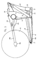
- Figures 1 and 2 show in rear elevational view and in plan view respectively a header 10 carried on an adapter 11 attached to the feeder house 12 of a combine harvester.
- the adapter is omitted for convenience of illustration.
- the header 10 includes a frame 13 defined by a main rear beam 14 and a plurality of forwardly extending arms 15 which extend downwardly from the beam 14 and then forwardly underneath a table 16 which extends across the header.
- a cutter bar 17 At the forward end of the table 16 is provided a cutter bar 17.
- a draper transport system 18 On top of the table 16 is provided a draper transport system 18 which carries the crop from the cutter bar across the header to a discharge location at the feeder house 12.
- the draper thus include two side drapers extending from respective ends of the header inwardly toward the feeder house and a center adapter section 18B which acts to feed the crop from the side drapers 18A rearwardly to the feeder housing.
- the header further includes a reel 19 including a beam 19A on which is mounted a plurality of reel bats (not shown) which are carried on the beam 19A for rotation with the beam around the axis of the beam.
- the beam is carried on reel support arms 19B which extend from the beam rearwardly and upwardly to a support bracket attached to the transverse main beam 14.
- the reel arms can be raised and lowered by hydraulic cylinders 19D connected between the respective arm and the beam 14.
- the reel is mounted on three arms 19B including two arms at the ends of the header and a single center arm.
- additional arms may be provided so that there are four such arms with two center arms being spaced apart either side of the adapter 11.
- Various different arrangements for accommodating such flexing movement are known and can be incorporated into the arrangement described herein, as is well known to one skilled in the art.
- the adapter 11 comprises a frame 20 which attaches to the feeder house 12 and carries at its lower end a pair of forwardly extending pivotal arms 21 which extend forwardly underneath respective ones of the frame members 15 of the header.
- the pivotal arms 21 can pivot upwardly and downwardly about a respective pivot pins 23 each independently of the other arm.
- Each arm is supported by a respective spring 24 carried on a respective stub arm 25 attached to the respective arm 21.
- the spring 24 provides tension on the stub arm 25 pulling it upwardly around the pin 23 which acts to pull up the respective arm 21 and provide a lifting force underneath the header at a lifting point partway along the respective frame member 15 and underneath the draper 18 and the table 16.
- a link 26 which extends from the frame 20 forwardly to the central bracket 19C of the beam arm support brackets.
- the link 26 is provided in the form of a hydraulic cylinder which allows adjustment of the length of the cylinder thus pivoting the header forwardly and rearwardly about the support point of the arms 21 on the underside of the header.
- the attitude of the header that is the angle of the table 16 to the horizontal can be tilted by operation of the cylinder forming the link 26.
- attitude of the header about an axis extending forwardly of the direction of movement that is at right angles to the transverse beam 14 is effected by the independent pivotal movement of the arms 21 provided by the springs 24 which act as a floatation system.
- the whole header can float upwardly and downwardly on the springs 24 with the link 26 pivoting to accommodate the upward and downward movement and the arms 21 pivoting about the respective pin 23.
- the table 16 provides behind the cutter bar 17 a skid plate 16A which is arranged to engage the ground.
- a skid plate 16A which is arranged to engage the ground.
- the springs are adjusted so that the springs act to support the majority of the weight of the header leaving a relatively small proportion of the weight to rest on the ground.
- the header can float upwardly and downwardly as the ground provides areas of different height with one end of the header being movable upwardly independently of the other end by independent flexing of the springs 24.
- the header tends to follow the ground level.
- the arrangement of the present invention provides an improvement by which the header is formed in a number of sections which are independently pivotal each relative to the next and in which adjustment of the lifting force provided by the springs 24 is transferred to each of the sections proportionally so that each section can float upwardly and downwardly and each section applies a force to the ground which is proportional to the total force of the whole header.
- the beam 14 is divided into a number of separate pieces depending upon the number of sections of the header.
- three sections including a center section 10A, a first wing section 10B and a second wing section 10C.
- the center section 10A is mounted at the adapter so that the arms 21 extend into engagement with the center section.
- the wing sections are pivotally connected to the center section such that each can pivot upwardly and downwardly about a respective pivot axis generally parallel to the direction of movement.
- each section of the beam 14 includes respective ones of the frame members 15 which support the respective portion of the table.
- Each section of the beam 14 includes respective ones of the frame members 15 which support the respective portion of the table.
- the end most frame member 15A of the wing section 10B is arranged at the break.
- the end frame member 15B of the center section 10A is spaced inwardly from the break leaving space for a pivot coupling 27 extending from the frame member 15A to the frame member 15B and defining a pivot pin 27A lying on the pivot axis between the wing section 10B and the center section 10A.
- the cutter bar 17 is also visible underneath the header at the forward end of the frame members 15 and at the front of the table 16.
- the cutter bar 17 is split at a junction 17A lying along the axis of the pin 27A so as to provide a pivot within the cutter bar allowing the cutter bar to bend at the junction 17A.
- the cutter bar can be formed in a manner which allows it to flex on the axis of the pin 27A thus avoiding the necessity for a break in the cutter bar.
- the cutter bar 17 is shown in more detail in Figures 9, 10 and 11.
- the cutter bar is of conventional shape including a U shaped member 17B with generally horizontal legs and a front curved nose 17C to which is attached the knife support flange 17D of a conventional nature.
- the knife support flange includes a plurality of holes 17E for mounting conventional knife guards shown in figures 10 and 11.
- a bridging link 17F is connected across the break 17A so as to hold the sections of the cutter bar 17 aligned while the pivotal movement occurs.
- the link 17F comprises a plate welded to one part of the cutter bar as indicated at 17B with the link or plates spanning the break 17A and extending to a pin 17H which is welded to the other part of the cutter bar as indicated at 17J with the link 17G being held in place by a nut 17L.
- the two sections 10A and 10B are supported each relative to the other for pivotal movement of the wing section 10B about an axis extending through the pin 27A and through the break 17A so that the wing section is supported at its inner end on the center section but can pivot downwardly at its outer end so that the weight at the outboard end is unsupported by the center section and causes downward or counter clockwise pivotal movement of the wing section 10B.
- the wing section 10C is mounted in an identical or symmetrical manner for pivotal movement about the other end of the center section 10A.
- the amount of pivotal movement allowed of the wing section relative to the center section about the axis of the pivot pin 27A is maintained at a small angle generally less than 6° and preferably less than 4° as controlled by suitable mechanical stop members which are provided at a suitable location with the required mechanical strength to support the wing frame section against upward or downward movement beyond the stop members.
- suitable stop members can be designed by a person skilled in the art and the details of the stop members are not described herein.
- the outboard weight of the wing section 10B is supported on an interconnecting linkage 30 which communicates that weight from the inner end of the beam 14 of the section 10B through to the support for the center section 10A at the springs 24.
- the linkage is shown particularly in Figures 4 and 6 and includes a tension link 31 extending from the inner end of the beam 14 to a bell crank 32 at the outer end of the center section 10A on the beam 14 together with a further tension link 33 which extends downwardly from the bell crank to a balance beam 34 located on the center section 10A at its inter connection with the arm 21.
- the linkage operates to transfer the outboard weight of the wing section inwardly to the center section and at the same time to balance the lifting force provided by the springs 24 so that it is proportionally applied to the center section and to the wing section.
- the header is attached to the combine feeder house using the float system described previously that supports the header so that it can be moved up when a vertical force about 1% to 15% of its weight is applied to the cutter bar from the ground.
- the reaction of the float linkage that typically supports 85% to 99% of the header weight on the header is used to balance the weight of the wings.
- the system is designed so that if the operator sets the float so that the float system supports 99% of the header weight then the remaining 1% will be evenly distributed across the cutter bar. If the operator changes the float so that 85% is supported by the combine harvester then the remaining 15% would also be evenly distributed across the cutter bar without the operator making adjustments.
- the total lifting force to each sections varied in proportion to the total lifting force but also that lifting force on each section is balanced across the width of section. As the sections are rigid between the ends, this requires that the lifting forces be balance between the ends to ensure the even distribution across the cutter bar of each section and thus of all the sections.
- This provides an arrangement in which the force required to lift the header is the same force at any location along the length of the cutter bar, whether that location is at the center section, at a junction between the center section and the wing section or at the wing section.
- This is achieved in this embodiment by the balancing system which transfers lifting force between the sections with the forces being balanced by the balance beam.
- the header frame sections and the reel sections are hinged and supported so that the reel will stay in approximately the same position relative to the cutter bar.
- the balance beam 34 as described in more detail hereinafter balances the lifting force applied to the ends of the center section relative to the lifting force which is applied to the outboard weight of the wing section so that the lifting force is even across the width of the header.
- a lifting force is applied by the ground or any other lifting mechanism for example merely manually lifting the header at a particular location across its width, that would cause the header to rise at that point and to fall at other points.
- the amount of force necessary to lift the header at that point will be the same as it is at other points and this lifting force can be varied for the total header and proportioned across the width of the header automatically by the balance beams as described hereinafter.
- the inboard weight of the wing section is transferred through the pivot 27 to the outboard end of the center section and that weight is transferred directly to the balance beam. Also the outboard weight of the wing section is transferred through the tension links and the bell crank to the balance beam. Yet further a lifting force from the arm 21 is applied to the balance beam.
- the balance beam is located immediately at the arm 21 and above the arm 21 so that the arm 21 extends forwardly to a forward lifting point 21A which engages underneath a forward end 34A of the balance beam.
- the lifting force from the arm 21 is applied upwardly at the point 21A which is forward of the beam 14 and underneath the table 16.
- the balance beam 34 extends rearwardly from the forward end 34A to a pivot 34B and from the pivot rearwardly to a rear end 34C to which is connected the tension link 33 at a bushing 33A.
- the tension link thus applies an upward pulling force F2 which act to support the outboard weight of the wing section.
- the pivot pin 34B is attached to the center section so that the weight from the center section is transferred to the pivot pin and through that pin to the balance beam. There is otherwise no direct connection between the center section and the arm 21 so that the weight of the center section is wholly applied through the pin to the balance beam as a force F1.
- the lifting force from the arm 21 is wholly applied to the outer end 34A of the balance beam as a force FT.
- these three forces are all applied to the balance beam and the balance beam acts to automatically proportion the forces F1 and F2 relative to the lifting force FT.
- the support assembly includes a first component which is the pin 34B to provide a lifting force for the center frame portion.
- the support assembly which is the linkage includes a second component which is a tension link 33 arranged to provide a lifting force F2 for the outboard weight of the second or wing frame portion.
- the whole support assembly including the balance beam, the lift arm 21 and the springs 24 are arranged to provide a floating movement for each of the first and second frame portions that is the center and wing frame portions relative to each other and relative to the propulsion vehicle such that upward pressure from the ground on the skid element 16A which is greater in a downward force for a part of the weight of the header and supported by the lifting force tends to lift each of the center and wing frame portions relative to the propulsion vehicle.
- the balance beam arrangement is arranged such that the first and second lifting forces F1 and F2 are varied proportionally as the total lifting force FT is varied.
- the balance beam 34 forms a balancing connection which supports these forces. It will be appreciated that the balance beam could be provided by other balancing connections which are not necessarily linear and not necessarily even mechanical. It is convenient that the balance beam is located at the arm 21 since there is a suitable location and space for receiving the balance beam and the forces can be readily applied at that location. However other mechanical arrangements can be provided where the balancing connection is located at other points.
- tension link provided by the link 32, link 33 and the bell crank 32 includes no spring connection and is a direct mechanical linkage so that the spring action or floating action of the wing section is provided by the spring 24.
- the balance beam extends parallel to the arm 21 so that the pivot pins 34B and 33A have an axis at right angles to the balance beam and to the arm 21.
- the forces extend generally at right angles to the arm 21 since the arm 21 is generally horizontal underneath the header frame and underneath the balance beam.
- the bell crank 32 is located and supported on the beam 14 so that the link 31 extends along the length of the beam 14 across the space 14A.
- the link 31 is located above the pivot 27A and communicates forces by tension.
- compression links could also be used in a different mechanical arrangement for example underneath the pivot.
- the tension link arrangement is convenient since it provides relatively low forces which can be readily accommodated using relatively light components.
- the bell crank includes a pivot 32A attached to a bracket 35 at the beam 14, the bracket 35 being supported by a brace 36.
- the bell crank carries a pointer 32B which projects upwardly to a visible point of the header so that the angle of the pointer 32B provides an indication to the operator of the vehicle of the attitude of the wing section relative to the center section.
- the pointer being mounted on the bell crank provides a relatively large mechanical advantage so that the changing angle of the pointer is greater than the changing angle of the wing section itself.
- the link 31 is pivotally attached to the bell crank at a pivot connection pin 32B.
- the length of the tension link 31 can be adjusted by a threaded section 31A at the end of the link 31 which is shown at the end attached to the section 10A on a bracket 37.
- the link 33 is adjustable in length by a threaded rod 33B.
- the upper end of the link 33 is connected to the bell crank at a pivotal fastener pin 33C which transfers the load from the tension link to the bell crank.
- the position of the pin 32B relative to the pivot point 32A is adjusted by a threaded rod 32C which is connected to a lever 32D which pivots about the pin 33C, thus adjusting the mechanical advantage of the bell crank to vary the mechanical advantage transferred from the outboard weight of the wing section relative to the force F2.
- the bell crank can be adjusted so that the forces F1 and F2 are balanced to produce approximately uniform contact pressure between the ground and the skid shoe.
- the arrangement of the bell crank is also designed so that it tends to provide a balance point at the straight condition of the cutter bar with the forces away from that point increasing so as to avoid hunting of the system and to tend to bring the system back to the straight condition when the forces are removed.
- the system is designed so that it takes a little less force to bring the cutterbar back to straight than it takes to move the cutterbar out of straight.
- the system is designed to overcome all friction and return it to a straight condition.
- the system is designed so that a minimum force will start raising or lowering the end of the cutterbar.
- the bell crank is designed so that the force will increase slightly as the cutterbar is moved to the maximum position up or down. Therefore the force required to return the cutterbar to the straight position is smaller than the force that was required to deflect it out of the straight position. This is what is defined as slightly stable.
- the system is designed to operate as follows:
- FIGs 7, 8 and 8A is shown an additional balance link 40 located within the balance beam 34 for providing additional forces thereon.
- the balance link 40 co-operates with a stop member 41 on the adapter frame 20.
- the balance link 40 also co-operates with a hanging strap 42 at its forward end opposite the rear end which engages the stop 41.
- the balance link is pivoted to the balance beam 34 at a pivot pin 43.
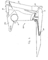
- the function of the balance link 40 is that when the adapter frame 20 is raised by the operator raising the feeder house of the combine harvester so as to lift the header away from the ground, the center section falls since its weight exceeds the lifting force of the springs 24 until the balance beam 34 contacts the bottom stop on frame 20 as shown in figure 5 and supports the center section. At that bottom stop position, the rear end of the balancing link 40 also engages the stop 41 which provides a force on the balance beam 34 tending to move the balance beam to a position in which the wing sections are raised to a straight condition of the cutter bar.
- Figures 7, 8 and 8A show the function of the linkage when operating off of the ground.
- the major portion of the header weight is supported by the float springs.
- the portion of the weight that is not supported by the float springs is supported by contact of the balance beam 34 with the down stop 41. This force is used to operate the balance link 40 to hold the cutterbar straight.
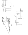
- Fig 8 shows the linkage in a position corresponding to a straight cutter bar.
- Balance link 40 and beam 34 are both in contact with the stop 41 and sharing the down load from the header that is not supported by the float spring. Force between beam 34 and stop 41 will reduce the force on rear tension link and tend to return cutterbar from concave up to straight position. Force between link 40 and stop 41 will be balanced by tension in the strap 42. The total of the force from the stop 41 and the link 40 and the force in the strap 42 will be balanced by a reaction at the pivot 43 on the. balance beam 34. The reaction at the pivot 43 produces a clockwise moment about the pivot 34B and increases the tension in the rear tension link 33 tending to return the cutterbar from concave to straight. Thus the cutterbar is held in straight position by the two opposing forces.
- Figure 7 shows the linkage in a position with the cutterbar in a concave up position.
- the link 40 is not making contact with the strap 42 therefore there is no significant force on the link 40.
- the balance beam 34 is in contact with the down stop 41 and will tend to rotate the balance beam 34 counter clockwise and move the cutterbar from concave up to straight.
- Fig 8A shows the linkage in a position with the cutterbar in a concave down position.
- the balance beam 34 is not in contact with the down stop 41 therefore it is not providing additional force to hold cutterbar in concave down position.
- the balance beam 40 is in contact with down stop 41 and the strap 42 is in tension, therefore the force from the down stop 41 will tend to pull the wings up into a straight cutterbar position.
- header section 50 There is a header section 50. It is divided into two sections left wing 50A and right wing 50B. They are connected with a hinge 51 at the main frame and a cutterbar hinge 52. There is an adapter 53 that is mounted on a combine and connected to the header by a top float link 54. This is connected to the adapter frame with a horizontal pivot 54A. This can be free to pivot vertically but be designed to take side load. It is connected to the header frame close to the hinge area. This could be a ball joint 54B that would allow the header to float up but restrain it from moving to the side relative to the adapter frame.
- a lower float link 55 is connected to each side of the adapter frame with pivot pin 55A
- the front of the link is connected to the balance beam 56 with a pivot pin 55B.
- Pivots 55A and 55B allow free rotation about a horizontal axis and some lateral motion such as can be obtained from a rubber bushing.
- An upward force is provided by float spring 57.
- a linkage system is provided to communicate the vertical force from the front pivot 55B of lower float link 55 into a generally horizontal force in link 58. This horizontal force is supported by the adapter frame at pivot 58A. The reaction on the header frame tends to raise the wing and cause it to pivot about pivots 51 and 52.
- the linkage system shown consists of the balance beam 56 connected to header frame leg with a horizontal pivot pin at 56A. The lower float link exerts an generally upward force at pivot 55B.
- the connecting link 59 is connected to the balance link with a pivot at 59A.
- the top of link 59 is connected to a bell crank 60 at 59B.
- the bell crank 60 is pivoted on the inner header frame at pivot 60A. Force from the link 59 produces a torque about pivot 60A. This torque is balanced by a force in the link 58. The reaction from these two forces produces an upward and outward force at the pivot 60A that balances the wing of the header.
- Suitable design of the linkage can result in the wing supported so that a uniform force is applied between the ground and the cutter bar.
- An adjustment can be provided so that the operator can adjust the balance of forces between the outer end of the cutter bar and the inner end of the cutterbar.
- additional wing sections can be provided so that there are a center section C, an inner or first wing section I and an outer or second wing section O on each side.
- the arrangement for transferring the forces is shown in Figure 13 which uses the same construction as previously described in relation to the first wing section including the balance beam 34 which communicates to the bell crank 32.
- a second balance beam 150 so that the tension link 31 from the bell crank 32 communicates forces to the balance beam 150 providing a lifting force at a pivot 151 on the first wing section and a lifting force through a tension link 152 to the second wing section.
- the balance beam 150 thus can be adjusted to provide a balancing of the forces between the center section, the first wing section and the second wing section using the principles as previously described.
- FIG. 14 and 15 is shown an alternative arrangement in which the mechanical linkages are replaced by hydraulic linkages.
- the spring 24 is replaced by a hydraulic cylinder 241 which forms part of a float system circuit system generally indicated at 242.
- the float system circuit includes an accumulator 243 in a conventional manner.
- a second cylinder 244 is provided to support the wing section 10B relative to the center section 10B at a position above the pivot 27.
- the cylinder 241 supports the center section together with the inboard weight of the wing section and the cylinder 244 supports the outboard weight of the wing section.
- the spring forces provided by these two cylinders in relation to the accumulator 243 can therefore be balanced automatically by the system so that when the total lifting force is changed by a float control valve 246, the lifting force to each of the wing section and the center section is proportionally balanced as previously described.
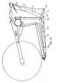
- Figure 20 shows the rear view of the left portion of the center frame 70 and the right portion of the left wing 71.
- the adapter frame is not shown in Figure 20.
- Figure 19 is a cross section view of the balance linkage at section A-A shown on figure 20.
- the adapter frame 72 is normally supported by the combine feeder housing (not shown).
- the float spring 73 is anchored to the top of the adapter frame 72A.
- the lower support link 74 is pivoted at the lower portion of the adapter frame at 72B.
- the float spring is attached to the lower support link and applies an upward force at 74A.
- the balance link 75 is mounted to pivot at 75A on the lower frame.
- the forward end of the lower support link is attached to the balance link at 75B.
- the rear end of the balance link pivots on a compression link 76 at 75C.
- the balance link supports the header by means of a vertical reaction at 75A and a vertical force from the rear compression link 76.
- Bell crank 77 is mounted to pivot on the center frame section at 77A.
- the vertical force from the compression link 76 is applied to the bell crank at 77B.
- the resulting torque is balanced by a tension force in an upper tension link 78 applied at a pin 78A.
- the wing 71 is pivoted at front pivot 71A and rear pivot 71B.
- the moment arm of the tension link 78 is adjusted by moving the pin 78A up or down in a slot 77C.
- At least one of the first and second lifting components, that is particularly the hydraulic cylinders is modified to include an actively driven control.
- the cylinder 244 is actively controlled for adjusting the height of the outboard end of the second portion in response to the output of a sensor responsive to changes in lifting force from the ground at points along the cutter bar.
Landscapes
- Life Sciences & Earth Sciences (AREA)
- Environmental Sciences (AREA)
- Agricultural Machines (AREA)
- Harvester Elements (AREA)
- Harvesting Machines For Root Crops (AREA)
Claims (22)
- Une moissonneuse de récolte de céréales, comprenant :une structure à châssis principale, s'étendant dans la largeur de la moissonneuse pour se déplacer en direction de l'avant, globalement à angle droit par rapport à la largeur, sur le sol incluant une culture à récolter ;un ensemble de montage pour supporter la structure à châssis principale sur un véhicule de propulsion ;une table de réception de culture, supportée sur la structure à châssis principale, dans la largeur de la moissonneuse ;une barre de découpage sur l'avant de la table, agencée pour se déplacer sur le sol, en une action de découpage, et portant une lame de découpeur, susceptible d'agir pour découper la culture lorsque la moissonneuse est déplacée en sens avant sur le sol, afin de déposer la culture sur la table ;un élément formant patin, s'étendant sur la largeur de la moissonneuse pour venir en prise avec le sol, pour supporter des forces de levée venant du sol, en des points quelconques de l'élément formant patin, en contact avec le sol, tendant à soulever la barre de découpage ;un système de transport de culture sur la table, pour déplacer la culture ayant été découpée vers un emplacement de décharge de la moissonneuse ;la structure à châssis principale comprenant une partie de châssis centrale, une première partie de châssis d'aile et une deuxième partie de châssis d'aile ;la première partie de châssis d'aile étant reliée à la partie de châssis centrale par un premier accouplement pivotant, agencé pour permettre un mouvement pivotant de la première partie de châssis d'aile par rapport à la partie de châssis centrale, autour d'un premier axe de pivotement s'étendant dans un plan parallèle à la direction avant, et coupant la barre découpeuse, de manière que, lorsque la première partie de châssis d'aile pivote par rapport à la partie de châssis centrale, la barre découpeuse fléchisse dans la zone adjacente au premier axe de pivotement, pour permettre d'accomplir le mouvement de pivotement ;le premier accouplement pivotant agissant ainsi pour supporter le poids venant de la première partie de châssis d'aile par le couplage pivotant, tandis que le poids venant de la première partie de châssis d'aile, extérieur au premier couplage de pivotement, tend à faire tourner la première partie de châssis d'aile autour du premier couplage de pivotement en direction du bas ;la deuxième partie de châssis d'aile étant connectée à la partie de cadre centrale par un deuxième couplage de pivotement, agencé pour permettre un mouvement pivotant de la deuxième partie de châssis d'aile par rapport à la partie de châssis centrale, autour d'un deuxième axe de pivotement s'étendant dans un plan parallèle à la direction avant, et coupant la barre découpeuse, de manière que, lorsque la deuxième partie de châssis d'aile pivote par rapport à la partie de châssis centrale, la barre découpeuse fléchisse dans la zone adjacente au deuxième axe de pivotement pour permettre que s'accomplisse le mouvement de pivotement ;le deuxième couplage de pivotement agissant ainsi pour supporter le poids venant de la deuxième partie de châssis d'aile par le deuxième couplage de pivotement, tandis que le poids venant de la deuxième partie de châssis d'aile, extérieur au deuxième couplage de pivotement, tend à faire tourner la deuxième partie de châssis d'aile autour du deuxième couplage de pivotement, en direction du bas ;l'ensemble de montage comprenant un premier et un deuxième ressort, agencés en des positions espacées transversalement sur la structure de châssis principale ;les premier et deuxième ressorts fournissant une première et une deuxième force de levée élastique, respectivement, qui produisent conjointement une force de levée élastique totale vis-à-vis du véhicule de propulsion, agissant pour supporter la structure de châssis principale, pour permettre un mouvement flottant par rapport au véhicule de propulsion, de manière qu'une pression vers le haut, venant du sol et appliquée à l'élément formant patin, qui est de valeur supérieure à une force orientée vers le bas, venant d'une partie du poids de la moissonneuse, non supportée par la force de levée, tende à lever la structure de châssis principale par rapport au véhicule de propulsion ;l'ensemble de montage étant agencé de manière que la force de levée élastique totale, fournie par les premier et deuxième ressorts, puisse être modifiée de manière que la force orientée vers le bas, totale, venant de la partie du poids de la structure de châssis principale, non supportée par la force de levée élastique totale, puisse être modifiée dans le but de modifier la pression totale exercée par l'élément formant patin sur le sol ;l'ensemble de montage comprenant un ensemble support central, communiquant depuis la force de levée élastique totale des premier et deuxième ressorts, une force de levée centrale, opposée au poids de la partie de châssis centrale et au poids venant de la première partie de châssis d'aile au premier couplage de pivotement, et au poids venant de la deuxième partie de châssis d'aile au deuxième couplage de pivotement ;l'ensemble de montage incluant une première liaison d'interconnexion communiquant, depuis la force de levée élastique totale, une première force de levée opposée au poids extérieur de la première partie de châssis d'aile ;l'ensemble de montage incluant une deuxième liaison d'interconnexion, communiquant, depuis la force de levée élastique totale, une deuxième force de levée, opposée au poids extérieur de la deuxième partie de châssis d'aile ;l'ensemble de support central et les première et deuxième liaisons d'interconnexion étant agencés de manière que la force de levée centrale et les première et deuxième forces de levée varient, lorsque la force de levée élastique totale varie, et de manière que la force de levée soit équilibrée sur la largeur des parties de châssis centrales et d'aile.
- La moissonneuse selon la Revendication 1, dans laquelle l'ensemble support central et les première et deuxième liaisons d'interconnexion sont agencés de manière que la force de levée centrale et les première et deuxième forces de levée varient de façon proportionnelle.
- La moissonneuse selon la Revendication 1 ou 2, dans laquelle l'ensemble de support central et les première et deuxième liaisons d'interconnexion comprennent une liaison d'équilibrage agencée de manière que l'ajustement de l'ensemble de montage, dans le but de produire une variation de la force de levée élastique totale, produise automatiquement un équilibrage de la force de levée centrale et des première et deuxième forces de levée, proportionnellement.
- La moissonneuse selon la Revendication 1, 2 ou 3, dans laquelle la première liaison d'interconnexion effectue un transfert du poids extérieur de la première partie de châssis d'aile à la partie de châssis centrale, et dans laquelle la deuxième liaison d'interconnexion effectue un transfert du poids extérieur de la deuxième partie de châssis d'aile vers la partie de châssis centrale.
- La moissonneuse selon l'une quelconque des Revendications précédentes, dans laquelle chacune des première et deuxième liaisons d'interconnexion est une liaison non élastique, et le couplage élastique de chacune est assuré par une connexion à un ressort respectif parmi le premier et le deuxième ressort de l'ensemble de montage, de manière que l'on produise un mouvement flottant, au moins partiellement, sous l'effet desdits premier et deuxième ressorts.
- La moissonneuse selon l'une quelconque des Revendications précédentes, dans laquelle l'ensemble support central et la première liaison d'interconnexion comprennent une première poutre de balancier, à laquelle sont appliquées, en tant que trois forces équilibrées, a) ladite première force de levée élastique venant du premier ressort, b) une partie de la force de levée centrale, et c) ladite première force de levée, et dans laquelle l'ensemble support central et la deuxième liaison d'interconnexion comprennent une deuxième poutre de balancier, sur laquelle sont appliquées, en tant que trois forces équilibrées, a) ladite deuxième force de levée élastique venant du deuxième ressort, b) une partie de la force de levée centrale, et c) ladite deuxième force de levée.
- La moissonneuse selon la Revendication 6, dans laquelle les première et deuxième poutres de balancier sont placées sur la partie de châssis centrale.
- La moissonneuse selon la Revendication 6 ou 7, dans laquelle les première et deuxième poutres de balancier s'étendent en direction de l'avant.
- La moissonneuse selon la Revendication 8, dans laquelle le premier ressort de l'ensemble de montage comprend un premier bras de levée s'étendant en direction avant, parallèlement à et au-dessous de la première poutre de balancier, et dans laquelle le deuxième ressort de l'ensemble de montage comprend un deuxième bras de levée s'étendant en direction de l'avant, parallèlement et au-dessous de la deuxième poutre de balancier.
- La moissonneuse selon la Revendication 9, dans laquelle le premier bras de levée est agencé pour appliquer à la première poutre de balancier la force a) en une position située à l'avant de la force b), appliquée à l'avant de la force c), et dans laquelle le deuxième bras de levée est agencé pour appliquer à la deuxième poutre de balancier une force a) en une position à l'avant de la force b) appliquée à l'avant de la force c).
- La moissonneuse selon la Revendication 6, 7, 8, 9 ou 10, dans laquelle la première liaison d'interconnexion comprend une première liaison de transfert de masse, s'étendant depuïs la première partie de châssis d'aile à la partie de châssis centrale, en une position située au-dessus du premier couplage de pivotement, et agencée pour se connecter à la première poutre de balancier pour lui appliquer ladite force c) en une direction orientée vers le haut, et dans laquelle la deuxième liaison d'interconnexion inclut une deuxième liaison de transfert de masse s'étendant depuis la deuxième partie de châssis d'aile vers la partie de châssis centrale, à une position située au-dessus du deuxième couplage de pivotement, et agencée pour se connecter à la deuxième poutre de balancier pour lui appliquer ladite force c) en une direction orientée vers le haut.
- La moissonneuse selon la Revendication 11, dans laquelle la première liaison de transfert de masse comprend un premier levier coudé sur la partie de châssis centrale, au-dessus de la première poutre de balancier, et dans laquelle la deuxième liaison de transfert de masse comprend un deuxième levier coudé sur la partie de châssis centrale, au-dessus de la deuxième poutre de balancier.
- La moissonneuse selon la Revendication 12, dans laquelle chacun des premier et deuxième leviers coudés est ajustable indépendamment pour équilibrer les forces b) et c) pour maintenir la barre découpeuse rectiligne lorsque la pression agissant vers le haut, depuis le sol, est constante sur la longueur de la barre découpeuse.
- La moissonneuse selon l'une quelconque des Revendications précédentes, dans laquelle chacune de la partie de châssis centrale et des première et deuxième parties de châssis d'aile comprend une poutre de châssis principale horizontale, et dans laquelle les premier et deuxième couplages de pivotement sont agencés au-dessous des poutres principales.
- La moissonneuse selon l'une quelconque des Revendications précédentes, dans laquelle le mouvement de pivotement, entre la première partie de châssis d'aile et la partie de châssis centrale, est inférieure à une ampleur totale de 6 degrés, et dans laquelle le mouvement de pivotement, entre la deuxième partie de châssis d'aile et la partie de châssis centrale, est inférieur à une ampleur totale de 6 degrés.
- La moissonneuse selon l'une quelconque des Revendications précédentes, dans laquelle le mouvement de pivotement, entre la première partie de châssis d'aile et la partie de châssis centrale, est inférieur à une ampleur totale de 4 degrés, et dans laquelle le mouvement de pivotement, entre la deuxième partie de châssis d'aile et la partie de châssis centrale, est inférieur à une ampleur totale de 4 degrés.
- La moissonneuse selon l'une quelconque des Revendications précédentes, dans laquelle la partie de châssis centrale et les première et deuxième parties de châssis d'aile sont non supportées par les roues au sol, de manière que la totalité des forces de levée venant du sol soient communiquées par l'intermédiaire dudit élément formant patin.
- La moissonneuse selon l'une quelconque des Revendications précédentes, dans laquelle l'ensemble de montage comprend un organe d'arrêt inférieur, agencé de manière que le mouvement flottant vers le bas de la partie de châssis centrale soit stoppé en une position inférieure lorsque la moissonneuse est levée en une position levée, dans laquelle l'élément formant patin est espacé du sol, de manière qu'il n'y ait aucune force de levée venant du sol, dans laquelle est prévu un premier mécanisme d'équilibrage, pour équilibrer la première partie de châssis d'aile en position alignée par rapport à la partie de châssis centrale, et un deuxième mécanisme d'équilibrage, pour équilibrer la deuxième partie de châssis d'aile en position alignée par rapport à la partie de châssis centrale, faisant que la barre découpeuse est rectiligne lorsque la moissonneuse est placée à la position levée.
- La moissonneuse selon la Revendication 18, dans laquelle :la première liaison d'interconnexion comprend une première poutre de balancier montée à pivotement, à laquelle sont appliquées, en tant que trois forces équilibrées, a) ladite force de levée venant du premier ressort, b) une partie du poids venant de la partie de châssis centrale et de ladite masse appliquée à la partie de châssis centrale depuis la première partie de châssis d'aile au premier couplage de pivotement, et c) ladite masse extérieure de la première partie de châssis d'aile ;la deuxième liaison d'interconnexion comprend une deuxième poutre de balancier montée à pivotement, à laquelle sont appliquées, en tant que trois forces équilibrées, a) ladite force de levée venant du deuxième ressort, b) une partie de la masse venant de la partie de châssis centrale et dudit poids appliqué à la partie de châssis centrale depuis la deuxième partie de châssis d'aile au deuxième couplage de pivotement, et c) ladite masse extérieure venant de la deuxième partie de châssis d'aileet dans laquelle chacun des premier et deuxième mécanismes d'équilibrage est agencé pour appliquer des forces d'équilibrage venant de l'organe d'arrêt inférieur, aux première et deuxième poutres d'équilibrage respectivement.
- La moissonneuse selon l'une quelconque des Revendications précédentes, dans laquelle la première liaison d'interconnexion, qui transfère la masse extérieure de la première partie de châssis d'aile à la partie de châssis centrale, comprend un premier ressort d'aile, une force élastique fournie de cette manière étant ajustable en réponse à la variation de la force de levée fournie par l'ensemble de montage, de manière que la force orientée vers le bas, de la première partie de châssis d'aile, varie séparément lorsque la force orientée vers le bas, totale, est modifiée, et dans laquelle la deuxième liaison d'interconnexion, qui transfère le poids extérieur de la deuxième partie de châssis d'aile à la partie de châssis centrale comprend un deuxième ressort d'aile, une force élastique fournie de cette manière étant ajustable en réponse à la variation de la force de levée fournie par l'ensemble de montage, de manière que la force orientée vers le bas de la deuxième partie de châssis d'aile varie séparément lorsque la force totale orientée vers le bas est modifiée.
- La moissonneuse selon l'une quelconque des Revendications précédentes, dans laquelle la première liaison d'interconnexion, qui transfère le poids extérieur de la première partie de châssis d'aile à la partie de châssis centrale, comprend un premier couplage à entraínement actif, servant à ajuster la hauteur de l'extrémité extérieure de la première partie de châssis d'aile, et dans laquelle est prévu un premier capteur réagissant à des variations de la force de levée, depuis le sol, en des points situés le long de la barre découpeuse pour commander le premier couplage entraíné de façon active, et dans laquelle la deuxième liaison d'interconnexion, qui transfère le poids extérieur de la deuxième partie de châssis d'aile à la partie de châssis centrale, comprend un deuxième couplage entraíné de façon active pour ajuster la hauteur de l'extrémité extérieure de la deuxième partie de châssis d'aile, et dans laquelle est prévu un deuxième capteur ,réagissant à des variations de la force de levée venant du sol, en des points situés sur la barre découpeuse, pour commander le deuxième couplage entraíné de façon active.
- La moissonneuse selon l'une quelconque des Revendications précédentes, dans laquelle :la structure de châssis principale comprend une première partie de châssis d'aile extérieure et une deuxième partie de châssis d'aile extérieure ;la première partie de châssis d'aile extérieure étant connectée à la première partie de châssis d'aile par un troisième couplage pivotant, agencé pour permettre un mouvement pivotant de la première partie de châssis d'aile extérieure par rapport à la première partie de châssis d'aile, autour d'un troisième axe de pivotement, s'étendant dans un plan parallèle à la direction avant et coupant la barre découpeuse, de manière que, lorsque la première partie de châssis d'aile extérieure pivote par rapport à la première partie de châssis d'aile, la barre découpeuse fléchisse dans la zone adjacente au troisième axe de pivotement pour permettre d'effectuer le mouvement de pivotement ;le troisième couplage de pivotement agissant ainsi pour supporter le poids venant de la première partie de châssis d'aile extérieure au troisième couplage de pivotement, tandis que le poids, venant de la première partie de châssis d'aile extérieure, extérieur au troisième couplage de pivotement, tend à faire tourner la première partie de châssis d'aile extérieure autour du troisième couplage de pivotement, en direction du bas ;la deuxième partie de châssis d'aile extérieure étant connectée à la deuxième partie de châssis d'aile par un quatrième couplage pivotant, agencé pour permettre un mouvement pivotant de la deuxième partie de châssis d'aile extérieure par rapport à la deuxième partie de châssis d'aile, autour d'un quatrième axe de pivotement, s'étendant dans un plan parallèle à la direction avant et coupant la barre découpeuse, de manière que, lorsque la deuxième partie de châssis d'aile extérieure pivote par rapport à la deuxième partie de châssis d'aile, la barre découpeuse fléchisse dans la zone adjacente au quatrième axe de pivotement, pour permettre que s'effectue le mouvement de pivotement ;le quatrième couplage de pivotement agissant ainsi pour supporter le poids venant de la deuxième partie de châssis d'aile extérieure au quatrième couplage de pivotement, tandis que le poids, venant de la deuxième partie de châssis d'aile extérieure, extérieur au quatrième couplage de pivotement, tend à faire tourner la deuxième partie de châssis d'aile extérieure autour du quatrième couplage de pivotement, en direction du bas ;la première partie de châssis d'aile extérieure étant connectée à la première partie de châssis d'aile par une troisième liaison d'interconnexion qui transfère le poids extérieur de la première partie de châssis d'aile extérieure à la première partie de châssis d'aile, la troisième liaison d'interconnexion étant agencée de manière que la force, orientée vers le bas, de la première partie de châssis d'aile extérieure, varie séparément, lorsque la force totale orientée vers le bas est modifiée ; etla deuxième partie de châssis d'aile extérieure étant connectée à la deuxième partie de châssis d'aile par une quatrième liaison d'interconnexion qui transfère le poids extérieur de la deuxième partie de châssis d'aile extérieure à la deuxième partie de châssis d'aile, la quatrième liaison d'interconnexion étant agencée de manière que la force, orientée vers le bas, de la deuxième partie de châssis d'aile extérieure, varie séparément, lorsque la force totale orientée vers le bas est modifiée.
Applications Claiming Priority (5)
| Application Number | Priority Date | Filing Date | Title |
|---|---|---|---|
| US29838501P | 2001-06-18 | 2001-06-18 | |
| US298385P | 2001-06-18 | ||
| US34213401P | 2001-12-26 | 2001-12-26 | |
| US342134P | 2001-12-26 | ||
| PCT/CA2002/000800 WO2002102138A1 (fr) | 2001-06-18 | 2002-05-30 | Tete de coupe en plusieurs parties a lame de coupe flexible |
Publications (2)
| Publication Number | Publication Date |
|---|---|
| EP1401256A1 EP1401256A1 (fr) | 2004-03-31 |
| EP1401256B1 true EP1401256B1 (fr) | 2005-06-29 |
Family
ID=26970629
Family Applications (1)
| Application Number | Title | Priority Date | Filing Date |
|---|---|---|---|
| EP02727138A Expired - Lifetime EP1401256B1 (fr) | 2001-06-18 | 2002-05-30 | Tete de coupe en plusieurs parties a lame de coupe flexible |
Country Status (10)
| Country | Link |
|---|---|
| US (1) | US6675568B2 (fr) |
| EP (1) | EP1401256B1 (fr) |
| AR (1) | AR040136A1 (fr) |
| AT (1) | ATE298498T1 (fr) |
| AU (1) | AU2002257470B2 (fr) |
| BR (1) | BR0210451A (fr) |
| CA (1) | CA2387898C (fr) |
| DE (1) | DE60204887T2 (fr) |
| EA (1) | EA005026B1 (fr) |
| WO (1) | WO2002102138A1 (fr) |
Cited By (4)
| Publication number | Priority date | Publication date | Assignee | Title |
|---|---|---|---|---|
| CN103931346A (zh) * | 2014-05-12 | 2014-07-23 | 北京奥天奇能源科技有限公司 | 秸秆集条式玉米收割台 |
| DE102015109191A1 (de) | 2014-06-25 | 2015-12-31 | Carl Geringhoff Gmbh & Co. Kg | Schneidwerk mit an Tragarmen gehaltener Haspel |
| DE102014009161A1 (de) | 2014-06-25 | 2015-12-31 | Carl Geringhoff Gmbh & Co. Kg | Schneidwerk mit Mittelteil und dazu verstellbaren Seitenteilen |
| EP3957154B1 (fr) * | 2019-04-10 | 2025-02-12 | GTS Do Brasil Ltda. | Plateforme de récolteuse avec un système de flottaison pour moulinet et barre de coupe |
Families Citing this family (149)
| Publication number | Priority date | Publication date | Assignee | Title |
|---|---|---|---|---|
| US7051505B2 (en) * | 2002-08-21 | 2006-05-30 | Greg Brannstrom | Tomato harvester |
| FR2852485B1 (fr) * | 2003-03-17 | 2006-01-06 | Machine pour grouper des produits tels que de l'herbe | |
| DE10331197B4 (de) * | 2003-07-10 | 2012-09-06 | Deere & Company | Erntegutaufnahmevorrichtung mit Fördergurtzusammenbau |
| CA2434981C (fr) * | 2003-07-11 | 2006-05-02 | Macdon Industries Ltd. | Tablier pour tete de coupe |
| CA2494034C (fr) * | 2005-01-25 | 2009-12-08 | Macdon Industries Ltd. | Gaine d'usure pour barre de coupe de moissonneuse |
| DE102005006216B4 (de) * | 2005-01-27 | 2007-06-21 | Maschinenfabrik Bernard Krone Gmbh | Selbstfahrende landwirtschaftliche Erntemaschine |
| US7222474B2 (en) * | 2005-04-29 | 2007-05-29 | Cnh America Llc | Ground sensing apparatus for a header of an agricultural harvesting machine |
| US7430846B2 (en) * | 2005-05-10 | 2008-10-07 | Deere & Company | Floating header with integrated float system for use with an agricultural windrower or combine |
| US7222475B2 (en) * | 2005-05-10 | 2007-05-29 | Deere & Company | Header hydraulic float system |
| US7191582B2 (en) * | 2005-05-10 | 2007-03-20 | Deere & Company | Header terrain following system |
| US7207164B2 (en) * | 2005-05-10 | 2007-04-24 | Deere & Company | Header hydraulic float suspension |
| US20080271426A1 (en) | 2006-02-10 | 2008-11-06 | Agco Corporation | Draper belt with crop-retaining rib |
| US20080276590A1 (en) * | 2006-02-10 | 2008-11-13 | Agco Corporation | Flexible draper and cutter bar with tilt arm for cutterbar drive |
| US20070193243A1 (en) * | 2006-02-10 | 2007-08-23 | Schmidt James R | Combine Harvester Draper Header Having Flexible Cutterbar |
| US8061114B2 (en) | 2006-02-16 | 2011-11-22 | Deere & Company | Combine head frame |
| US7426817B2 (en) * | 2006-03-02 | 2008-09-23 | Deere & Company | Independent center reel position adjustment for an agricultural harvesting machine |
| US7467506B2 (en) * | 2006-03-02 | 2008-12-23 | Deere & Company | Lockout for float arms in a cutting platform of an agricultural harvesting machine |
| US7478521B2 (en) * | 2006-03-02 | 2009-01-20 | Deere & Company | Flexible cutting platform to follow ground contour in an agricultural harvesting machine |
| US7805921B2 (en) * | 2006-06-14 | 2010-10-05 | Deere & Company | Reel height control for flexible cutting platform in an agricultural harvesting machine |
| US7520115B2 (en) * | 2006-09-15 | 2009-04-21 | Deere & Company | Header float arm load compensation |
| CA2561463C (fr) * | 2006-09-22 | 2012-09-11 | Macdon Industries Ltd. | Dispositif pour maintenir l'equilibre des ailes d'un tablier multisections de recolteuse |
| US7918076B2 (en) * | 2006-09-25 | 2011-04-05 | Macdon Industries Ltd. | Device for maintaining wing balance on a multi-section header |
| AU2008200792B2 (en) * | 2007-03-12 | 2012-11-01 | Deere & Company | Floating header with integrated float system for use with an agricultural windrower or combine |
| US7614206B2 (en) * | 2007-06-04 | 2009-11-10 | Claas Selbstfahrende Erntemaschinen Gmbh | Winged header apparatus and method for a combine |
| US7448491B1 (en) | 2007-06-04 | 2008-11-11 | Claas Selbstfahrende Erntemaschinen Gmbh | Combine header belt tensioning apparatus and method |
| US8117812B2 (en) * | 2007-08-28 | 2012-02-21 | Macdon Industries Ltd. | Header transport |
| US20090266044A1 (en) | 2008-04-25 | 2009-10-29 | Coers Bruce A | Integrated draper belt support and skid shoe in an agricultural harvesting machine |
| US20090277144A1 (en) | 2008-05-09 | 2009-11-12 | Agco Corporation | Spring flotation for center deck of draper header |
| US20090277148A1 (en) | 2008-05-09 | 2009-11-12 | Agco Corporation | Flexible draper and cutter bar having shiftable crop divider with deflector |
| US7886511B2 (en) | 2008-05-09 | 2011-02-15 | Agco Corporation | Draper head with flexible cutterbar having rigid center section |
| EP2312927B1 (fr) | 2008-05-09 | 2011-12-28 | Agco Corporation | Déflecteur central de moissons pour tête de tuloteuse |
| EP2315514B1 (fr) | 2008-05-09 | 2012-04-25 | Agco Corporation | Plage de déplacement de barre de coupe réglable pour organe de coupe à barre de coupe souple |
| US7921627B2 (en) * | 2008-05-09 | 2011-04-12 | Agco Corporation | Interlocking belt guards for a draper header |
| US20090277145A1 (en) | 2008-05-09 | 2009-11-12 | Agco Corporation | Header height control system with multiple potentiometer input |
| US7650736B1 (en) * | 2008-07-16 | 2010-01-26 | Deere & Company | Center conveyor front coupler for a draper cutting platform |
| US8635842B2 (en) * | 2009-08-05 | 2014-01-28 | Kevin Markt | Flexible row crop header for an agricultural harvester |
| US8051633B2 (en) * | 2010-03-29 | 2011-11-08 | Cnh America Llc | Cutterbar adjustment support for a crop harvesting header |
| US7930871B1 (en) * | 2010-03-29 | 2011-04-26 | Cnh America Llc | Cutterbar support for a crop harvesting header |
| US7950212B1 (en) * | 2010-03-29 | 2011-05-31 | Cnh America Llc | Cutterbar support for a crop harvesting header |
| US8205421B2 (en) * | 2010-06-16 | 2012-06-26 | Agco Corporation | Belt guard crop dam for flexible draper header |
| US7958711B1 (en) | 2010-06-16 | 2011-06-14 | Agco Corporation | Crop deflector for ends of draper belt of flexible draper header |
| US8087224B1 (en) * | 2010-09-16 | 2012-01-03 | Deere & Company | Flexible draper platform with pivot geometry |
| US7992372B1 (en) * | 2010-09-16 | 2011-08-09 | Deere & Company | Draper platform with breakaway joint |
| US8863489B2 (en) | 2011-03-30 | 2014-10-21 | H & S Manufacturing Co., Inc. | Tine drive cam for windrow merger |
| US8336280B2 (en) * | 2011-05-20 | 2012-12-25 | Deere & Company | Pivoting center conveyor for draper platform |
| US9258944B2 (en) * | 2011-06-06 | 2016-02-16 | Jose Luis Allochis | Flexible platform joined to a conveyor belt for a combine harvester |
| US8272198B1 (en) * | 2011-06-06 | 2012-09-25 | Allochis Jose Luis | Flexible platform jointed to a conveyor belt for a combine harvesting, chopping and spinning machine |
| GB201112453D0 (en) * | 2011-07-20 | 2011-08-31 | Cnh Belgium Nv | Header assembly for a harvesting machine |
| CA2796120C (fr) * | 2011-11-16 | 2014-08-26 | Macdon Industries Ltd. | Faucheuse a dispositif flottant |
| US8479483B1 (en) | 2011-12-27 | 2013-07-09 | Agco Corporation | Flexible draper head providing reduced crop residue accumulation |
| US8752360B2 (en) * | 2011-12-28 | 2014-06-17 | Agco Corporation | Variable length header truss for harvesting header |
| US8857143B2 (en) * | 2011-12-28 | 2014-10-14 | Agco Corporation | Frame for harvesting header with continuous section |
| US8695315B2 (en) * | 2012-08-09 | 2014-04-15 | Deere & Company | Draper header with pivoting side draper conveyors |
| US8752359B2 (en) * | 2012-08-31 | 2014-06-17 | Macdon Industries Ltd. | Draper support of a crop harvesting header |
| US8484939B1 (en) * | 2012-08-31 | 2013-07-16 | Macdon Industries Ltd. | Draper seal for crop harvesting header |
| US8511050B1 (en) * | 2012-08-31 | 2013-08-20 | Macdon Industries Ltd. | Draper support of a crop harvesting header |
| US8601779B1 (en) * | 2012-09-04 | 2013-12-10 | Cnh America Llc | System for cutterbar support having torsion device with elastic material and load limiting apparatus |
| DE102012108835A1 (de) * | 2012-09-19 | 2014-03-20 | Claas Selbstfahrende Erntemaschinen Gmbh | Schneidwerk |
| US9258941B2 (en) * | 2012-11-19 | 2016-02-16 | Macdon Industries Ltd. | Rotary crop harvesting machine with cutter bar tilt control |
| CA2799093A1 (fr) | 2012-12-18 | 2014-06-18 | Honey Bee Manufacturing Ltd. | Element etanche de convoyeur a toile pour bec cueilleur de recolte |
| DE102013100322A1 (de) * | 2013-01-14 | 2014-07-17 | Claas Selbstfahrende Erntemaschinen Gmbh | Schneidwerk |
| US8833048B2 (en) | 2013-02-14 | 2014-09-16 | Honey Bee Manufacturing, Ltd. | Harvesting header bat with adjustably spaced quick release fingers |
| US9198349B2 (en) | 2013-07-12 | 2015-12-01 | Deere & Company | Articulated harvesting head ground force control circuit |
| US9144199B2 (en) * | 2013-08-30 | 2015-09-29 | Deere & Company | Articulated harvesting head load sensor arrangement |
| US10021823B2 (en) | 2013-12-30 | 2018-07-17 | Honey Bee Manufacturing Inc. | Harvesting header transport apparatus and method |
| US9901032B2 (en) | 2013-12-30 | 2018-02-27 | Honey Bee Manufacturing Ltd. | Harvesting header transport |
| US9392747B2 (en) | 2014-01-30 | 2016-07-19 | Macdon Industries Ltd. | Finger drive for a crop feed roller |
| US9844183B2 (en) | 2014-03-26 | 2017-12-19 | Honey Bee Manufacturing Ltd. | Cam reel with complex bat path |
| CA2847456C (fr) | 2014-03-26 | 2021-01-19 | Honey Bee Manufacturing Ltd. | Rabatteur a came a chemin de lattes complexe |
| US9615513B2 (en) * | 2014-05-08 | 2017-04-11 | Roc S.R.L. | Harvester pick-up support |
| CA2853947A1 (fr) | 2014-06-09 | 2015-12-09 | Honey Bee Manufacturing Ltd. | Mecanisme d'entrainement de couteau de tete d'abatteuse-ebrancheuse |
| DE102014009156A1 (de) * | 2014-06-25 | 2015-12-31 | Carl Geringhoff Gmbh & Co. Kg | Schneidwerk mit Mittelteil und seitlich dazu angeordneten Seitenteilen |
| US10201125B2 (en) | 2014-09-05 | 2019-02-12 | Cnh Industrial America Llc | Combined center cam and reel arm |
| CA2876686C (fr) | 2014-12-24 | 2021-01-19 | Honey Bee Manufacturing Ltd. | Systeme de moulinet |
| US9775291B2 (en) | 2014-12-29 | 2017-10-03 | Macdon Industries Ltd. | Gauge wheels for a multi-section agricultural header |
| CA3062675C (fr) | 2015-03-13 | 2021-03-23 | Honey Bee Manufacturing Ltd. | Commande d'un systeme de positionnement d'un accessoire agricole |
| US10462966B2 (en) | 2015-03-13 | 2019-11-05 | Honey Bee Manufacturing Ltd. | Controlling a positioning system for an agricultural implement |
| BR102016005189B1 (pt) * | 2015-03-13 | 2020-11-17 | Cnh Industrial Belgium Nv | Colheitadeira agricola |
| US9402343B1 (en) * | 2015-04-23 | 2016-08-02 | Jose Luis Allochis | Flexible cutterbar assembly for a harvesting platform |
| US9668412B2 (en) | 2015-05-01 | 2017-06-06 | Deere & Company | Harvesting head height control circuit |
| US9814178B2 (en) * | 2015-09-29 | 2017-11-14 | Deere & Company | Support bracket for combine header |
| DE102015116892A1 (de) * | 2015-10-05 | 2017-04-06 | Carl Geringhoff Gmbh & Co. Kg | Schneidwerk mit verstellbarer Seitenrahmenentlastung |
| AU2019202983B2 (en) * | 2016-06-21 | 2020-04-30 | Macdon Industries Ltd. | Crop machine with an electronically controlled hydraulic cylinder flotation system |
| US10617059B2 (en) * | 2016-06-21 | 2020-04-14 | Macdon Industries Ltd. | Crop machine with an electronically controlled hydraulic cylinder flotation system |
| CA2937639C (fr) | 2016-07-29 | 2026-04-14 | Honey Bee Manufacturing Ltd. | Mecanisme de coupe de recolteuse |
| US10462968B2 (en) * | 2016-11-24 | 2019-11-05 | Macdon Industries Ltd. | Header with flexible crop cutting knife |
| CA3081598C (fr) | 2016-11-24 | 2022-09-06 | Macdon Industries Ltd. | Organe de coupe a sections multiples avec lame de coupe de recolte souple |
| US10375882B2 (en) * | 2017-04-19 | 2019-08-13 | Cnh Industrial America Llc | Multi-sectional header frame |
| US10542669B2 (en) | 2017-04-28 | 2020-01-28 | Deere & Company | Multi-section header with offset pivot axis |
| US10524422B2 (en) * | 2017-04-28 | 2020-01-07 | Deere & Company | Harvesting head constant force assembly |
| US10405474B2 (en) | 2017-04-30 | 2019-09-10 | Deere & Company | Multilink connection between harvesting head adapter frame and mainframe |
| BR102017010859B1 (pt) * | 2017-05-24 | 2022-12-13 | Cnh Industrial Brasil Ltda | Conjunto estrutural para montagem de uma plataforma |
| BR102017010857A2 (pt) * | 2017-05-24 | 2018-12-18 | CNH Industrial Brasil Ltda. | conjunto estrutural para montagem de uma plataforma e máquina colhedora |
| AU2017203981B2 (en) * | 2017-06-13 | 2019-07-04 | Macdon Industries Ltd | Gauge wheels for a multi-section agricultural header |
| DE102017113776A1 (de) * | 2017-06-21 | 2018-12-27 | Carl Geringhoff Gmbh & Co. Kg | Aus mehreren Sektionen zusammengesetztes Schneidwerk mit Knickschutz und Verfahren zur Höhenregelung des Schneidwerks |
| US10440888B2 (en) * | 2017-06-30 | 2019-10-15 | Cnh Industrial America Llc | Draper belt system with distance change of pivoting roller |
| US10299437B2 (en) * | 2017-07-17 | 2019-05-28 | Cnh Industrial America Llc | Header for an agricultural vehicle with deformable supports |
| US10321630B2 (en) * | 2017-07-27 | 2019-06-18 | Macdon Industries Ltd. | Agricultural header with ground engaging gauge members for above ground cutting |
| CA2974621C (fr) | 2017-07-27 | 2019-11-05 | Macdon Industries Ltd. | Bec cueilleur agricole avec elements de calibration de prise au sol pour coupe au-dessus du sol |
| CA2974636A1 (fr) | 2017-07-27 | 2019-01-27 | Macdon Industries Ltd. | Bec cueilleur pour machine de recolte de culture |
| US10820509B2 (en) * | 2017-08-08 | 2020-11-03 | Cnh Industrial America Llc | Foldable corn head |
| US10433483B2 (en) | 2017-08-21 | 2019-10-08 | Cnh Industrial America Llc | Agricultural header with one or more movable wing sections |
| US10356981B2 (en) | 2017-09-15 | 2019-07-23 | Cnh Industrial America Llc | Agricultural header with constant reel to cutter relationship |
| US10582660B2 (en) | 2017-10-04 | 2020-03-10 | Deere & Company | Agricultural harvesting head with float arm pivots below reciprocating knives |
| US10537063B2 (en) | 2017-10-11 | 2020-01-21 | Deere & Company | Folding agricultural head |
| US10426088B2 (en) | 2017-10-11 | 2019-10-01 | Deere & Company | Center feed assembly for a draper |
| US10517215B2 (en) | 2017-10-12 | 2019-12-31 | Deere & Company | Roll center for attachment frame control arms |
| US10433486B2 (en) | 2017-10-16 | 2019-10-08 | Deere & Company | System and method for wing float on a combine draper header |
| US10568266B2 (en) * | 2017-10-17 | 2020-02-25 | Deere & Company | Self-contained combine draper wing leveler |
| CA2993727C (fr) * | 2018-02-01 | 2021-05-04 | Macdon Industries Ltd. | Collecteur agricole dote d'une commande de flottement |
| CN108419510B (zh) * | 2018-04-26 | 2023-07-25 | 郑宇虎 | 一种多功能灌木收获机 |
| US10813289B2 (en) * | 2018-06-05 | 2020-10-27 | Deere & Company | Single top beam folding corn head mainframe |
| US10820510B2 (en) * | 2018-06-15 | 2020-11-03 | Deere & Company | Cutterbar angle change with four bar linkage |
| US10952375B2 (en) | 2018-06-29 | 2021-03-23 | Macdon Industries Ltd | Crop header with wing balance calibration |
| US10945370B2 (en) | 2018-08-16 | 2021-03-16 | Deere & Company | System and method for ground following of a combine header with flexible cutter bar |
| EA038881B1 (ru) * | 2018-08-27 | 2021-11-01 | Макдон Индастриз Лтд. | Жатка для сельскохозяйственной культуры с калибровкой баланса крыла |
| US11032970B2 (en) * | 2018-10-30 | 2021-06-15 | Deere & Company | Varying a hydraulic cylinder mechanical advantage to obtain smoother float pressure |
| EP3879958B1 (fr) * | 2018-11-16 | 2022-12-07 | CNH Industrial Belgium NV | Gestion de limite pour actionnement à suivi du sol automatique sur une tête d'abattage à segments multiples |
| WO2020101871A1 (fr) * | 2018-11-16 | 2020-05-22 | Cnh Industrial America Llc | Collecteur à cadre rigide modulaire |
| US12150409B2 (en) * | 2018-11-16 | 2024-11-26 | Cnh Industrial America Llc | Airbag system for a harvester header |
| EP3937612B1 (fr) * | 2019-03-11 | 2023-04-05 | CNH Industrial Belgium NV | Véhicule agricole à hauteur de levage réglable sur la base de l'identification de la table de coupe |
| US11272659B2 (en) | 2019-03-27 | 2022-03-15 | Deere & Company | Controlled or tuned float on an agricultural harvester to modify float response |
| AR118624A1 (es) * | 2019-04-10 | 2021-10-20 | Cnh Ind America Llc | Sistema de detección de sobrecarga para un cabezal de cosecha |
| US11224164B2 (en) | 2019-04-23 | 2022-01-18 | Deere & Company | Damped float response on an agricultural harvester |
| US11219162B2 (en) * | 2019-04-23 | 2022-01-11 | Deere & Company | Controlled header lowering on an agricultural harvester |
| US11191212B2 (en) | 2019-04-23 | 2021-12-07 | Deere & Company | Controlled float on an agricultural harvester for header leveling |
| US11212963B2 (en) | 2019-05-16 | 2022-01-04 | Cnh Industrial America Llc | Failsafe mode for articulating harvesting header |
| EP3741200B1 (fr) * | 2019-05-20 | 2024-01-10 | CNH Industrial Belgium N.V. | Système et procédé de commande pour moissonneuse agricole |
| DE102019125282A1 (de) | 2019-09-19 | 2021-03-25 | Carl Geringhoff Gmbh & Co. Kg | Schneidwerk mit höhenelastisch gelagerten Schneidelementen |
| US11483971B2 (en) | 2019-10-18 | 2022-11-01 | Cnh Industrial America Llc | Cutter bar support linkage |
| US11497164B2 (en) * | 2019-10-22 | 2022-11-15 | Cnh Industrial America Llc | Header suspension for pivoting header of combine harvester |
| US11406058B2 (en) | 2019-10-25 | 2022-08-09 | Cnh Industrial America Llc | Cutter bar support linkage |
| US11457564B2 (en) | 2019-11-22 | 2022-10-04 | Cnh Industrial America Llc | Torsional stiffness transfer mechanism for a hinged harvester head |
| US11350558B2 (en) | 2019-11-26 | 2022-06-07 | Cnh Industrial America Llc | Harvester head support torque transfer mechanism |
| US11617300B2 (en) * | 2019-12-23 | 2023-04-04 | Cnh Industrial America Llc | Locking mechanism for an agricultural header |
| CN111502601A (zh) * | 2020-04-21 | 2020-08-07 | 天津市飞奥达风能设备有限公司 | 一种抽油机用配重装置 |
| US12507630B2 (en) * | 2020-04-21 | 2025-12-30 | Cnh Industrial America Llc | Reel adjustment for an agricultural header |
| US11778943B2 (en) | 2020-05-29 | 2023-10-10 | Deere & Company | Lockout system for header |
| US11559000B2 (en) | 2020-05-29 | 2023-01-24 | Deere & Company | Lockout system for header |
| US20240180078A1 (en) * | 2021-03-29 | 2024-06-06 | Macdon Industries Ltd | Flexing header with float system |
| EP4066617B1 (fr) * | 2021-03-31 | 2025-05-07 | CNH Industrial Belgium N.V. | Entraînement par courroie pour entraîner le récolteur d'une moissonneuse-batteuse |
| US12396387B2 (en) | 2021-07-20 | 2025-08-26 | Deere & Company | Automated lockout system for header |
| US12402561B2 (en) | 2021-07-20 | 2025-09-02 | Deere & Company | Automated lockout system for header |
| US12396393B2 (en) | 2021-07-20 | 2025-08-26 | Deer & Company | Automated lockout system for header |
| US12239049B2 (en) * | 2021-08-19 | 2025-03-04 | Macdon Industries Ltd. | Header with flexible cutter bar assembly |
| US12575497B2 (en) | 2021-09-08 | 2026-03-17 | Deere & Company | Automated lockout system for header |
| CN114148011B (zh) * | 2021-12-23 | 2025-04-04 | 桂林中昊力创机电设备有限公司 | 胎体帘布裁断插补式避刀托料浮动杆机构 |
| CN115064323B (zh) * | 2022-07-28 | 2024-10-18 | 三门峡宏鑫新材料科技有限公司 | 一种数控自动化连续式导线绕包机的导线切割控制方法 |
| DE112024002053A5 (de) * | 2023-05-12 | 2026-04-02 | Carl Geringhoff Gmbh & Co. Kommanditgesellschaft | Pick-up-vorsatzgerät für eine erntemaschine |
Family Cites Families (15)
| Publication number | Priority date | Publication date | Assignee | Title |
|---|---|---|---|---|
| US2915870A (en) * | 1958-03-27 | 1959-12-08 | Horace D Hume | Floating cutter bar support mounting |
| NL6414183A (fr) * | 1964-12-05 | 1966-06-06 | ||
| NL6401807A (fr) * | 1964-02-26 | 1965-08-27 | ||
| US4409780A (en) | 1982-03-11 | 1983-10-18 | Kansas State University Research Foundation | Folding header assembly |
| US4446683A (en) | 1982-09-29 | 1984-05-08 | Canadian Cooperative Implements Limited | Knife drive |
| US4487004A (en) * | 1983-06-03 | 1984-12-11 | Kejr Melvin P | Combine harvester apparatus |
| DE3441209A1 (de) | 1984-11-10 | 1986-05-15 | Claas Ohg, 4834 Harsewinkel | Schneidwerksmulde fuer erntemaschinen mit flexiblem schneidwerk |
| CA1267292A (fr) * | 1986-09-10 | 1990-04-03 | Roger Lee Patterson | Caisse d'arrivee pour moissonneuse-batteuse |
| DE3722143C2 (de) | 1987-07-04 | 1996-03-28 | Claas Ohg | Gutaufnahmevorrichtung für Erntemaschinen, insbesondere für selbstfahrende Mähdrescher |
| US4956966A (en) * | 1988-06-22 | 1990-09-18 | Macdon Industries Ltd. | Header for a combine harvesting machine |
| DE3906456A1 (de) * | 1989-03-01 | 1990-09-06 | Claas Ohg | Selbstfahrender maehdrescher mit zweigeteiltem schneidwerk |
| FR2685162B1 (fr) * | 1991-12-20 | 1994-02-11 | Bourgoin Ets J | Dispositif cueilleur repliable pour la recolte du mauis ou plantes similaires. |
| CA2110775C (fr) | 1993-12-06 | 1999-03-02 | Gregory J. Honey | Adaptateur d'alimentation permettant de relier le collecteur et le bati d'alimentateur d'une moissonneuse-batteuse |
| US5673543A (en) * | 1996-01-04 | 1997-10-07 | Byron Enterprises, Inc | Foldable corn head with unobstructed auger |
| DE19635992A1 (de) * | 1996-09-05 | 1998-03-12 | Same Spa | Selbstfahrende landwirtschaftliche Erntemaschine |
-
2002
- 2002-05-29 CA CA002387898A patent/CA2387898C/fr not_active Expired - Lifetime
- 2002-05-30 EA EA200400051A patent/EA005026B1/ru active IP Right Revival
- 2002-05-30 DE DE60204887T patent/DE60204887T2/de not_active Expired - Lifetime
- 2002-05-30 WO PCT/CA2002/000800 patent/WO2002102138A1/fr not_active Ceased
- 2002-05-30 BR BR0210451-2A patent/BR0210451A/pt active Search and Examination
- 2002-05-30 EP EP02727138A patent/EP1401256B1/fr not_active Expired - Lifetime
- 2002-05-30 AU AU2002257470A patent/AU2002257470B2/en not_active Expired
- 2002-05-30 AT AT02727138T patent/ATE298498T1/de not_active IP Right Cessation
- 2002-06-03 US US10/159,981 patent/US6675568B2/en not_active Expired - Lifetime
-
2003
- 2003-05-28 AR ARP030101865A patent/AR040136A1/es active IP Right Grant
Cited By (7)
| Publication number | Priority date | Publication date | Assignee | Title |
|---|---|---|---|---|
| CN103931346A (zh) * | 2014-05-12 | 2014-07-23 | 北京奥天奇能源科技有限公司 | 秸秆集条式玉米收割台 |
| DE102015109191A1 (de) | 2014-06-25 | 2015-12-31 | Carl Geringhoff Gmbh & Co. Kg | Schneidwerk mit an Tragarmen gehaltener Haspel |
| DE102014009161A1 (de) | 2014-06-25 | 2015-12-31 | Carl Geringhoff Gmbh & Co. Kg | Schneidwerk mit Mittelteil und dazu verstellbaren Seitenteilen |
| US9526206B2 (en) | 2014-06-25 | 2016-12-27 | Carl Geringhoff Gmbh & Co. Kg | Header with center part and side parts adjustable relative to the center part |
| DE102014009161B4 (de) | 2014-06-25 | 2023-01-26 | Carl Geringhoff Gmbh & Co. Kg | Schneidwerk mit Mittelteil und dazu verstellbaren Seitenteilen |
| DE102015109191B4 (de) | 2014-06-25 | 2024-07-25 | Carl Geringhoff Gmbh & Co. Kg | Schneidwerk mit an Tragarmen gehaltener Haspel |
| EP3957154B1 (fr) * | 2019-04-10 | 2025-02-12 | GTS Do Brasil Ltda. | Plateforme de récolteuse avec un système de flottaison pour moulinet et barre de coupe |
Also Published As
| Publication number | Publication date |
|---|---|
| DE60204887T2 (de) | 2006-04-27 |
| CA2387898A1 (fr) | 2002-12-18 |
| WO2002102138A1 (fr) | 2002-12-27 |
| DE60204887D1 (de) | 2005-08-04 |
| BR0210451A (pt) | 2004-08-17 |
| ATE298498T1 (de) | 2005-07-15 |
| EA005026B1 (ru) | 2004-10-28 |
| CA2387898C (fr) | 2005-01-11 |
| AU2002257470B2 (en) | 2007-01-18 |
| US20030074876A1 (en) | 2003-04-24 |
| US6675568B2 (en) | 2004-01-13 |
| EA200400051A1 (ru) | 2004-06-24 |
| AR040136A1 (es) | 2005-03-16 |
| EP1401256A1 (fr) | 2004-03-31 |
Similar Documents
| Publication | Publication Date | Title |
|---|---|---|
| CA2387898C (fr) | Organe de coupe de recoltes a sections multiples et a couteau flexible | |
| AU2002257470A1 (en) | Multi-section header with flexible crop cutting knife | |
| US7918076B2 (en) | Device for maintaining wing balance on a multi-section header | |
| AU2007299524B2 (en) | Device for maintaining wing balance on a multi-section header | |
| CA2913937C (fr) | Roues de jauge pour un organe de coupe agricole a plusieurs sections | |
| US10701862B2 (en) | Agricultural header with float control | |
| EP3469876B1 (fr) | Système pour le flottement d'une aile sur une moissonneuse-batteuse a tablier | |
| CA3081598C (fr) | Organe de coupe a sections multiples avec lame de coupe de recolte souple | |
| EP3520597B1 (fr) | Tête de machine agricole avec commande de flotteur | |
| CA2307176A1 (fr) | Ecimeuse a lame de coupe souple | |
| CA3026913C (fr) | Andaineuse comportant un couteau de recolte flexible | |
| CA3033127C (fr) | Dispositif de montage transversal de vis helicoidale destine a une tete de recolteuse flexible | |
| AU2018305787B2 (en) | Header for a crop harvesting machine having a twisted side draper | |
| AU2019204082B2 (en) | A crop harvesting header | |
| AU2019200889B2 (en) | Header with flexible crop cutting knife |
Legal Events
| Date | Code | Title | Description |
|---|---|---|---|
| PUAI | Public reference made under article 153(3) epc to a published international application that has entered the european phase |
Free format text: ORIGINAL CODE: 0009012 |
|
| 17P | Request for examination filed |
Effective date: 20040119 |
|
| AK | Designated contracting states |
Kind code of ref document: A1 Designated state(s): AT BE CH CY DE DK ES FI FR GB GR IE IT LI LU MC NL PT SE TR |
|
| AX | Request for extension of the european patent |
Extension state: AL LT LV MK RO SI |
|
| GRAP | Despatch of communication of intention to grant a patent |
Free format text: ORIGINAL CODE: EPIDOSNIGR1 |
|
| GRAS | Grant fee paid |
Free format text: ORIGINAL CODE: EPIDOSNIGR3 |
|
| GRAA | (expected) grant |
Free format text: ORIGINAL CODE: 0009210 |
|
| AK | Designated contracting states |
Kind code of ref document: B1 Designated state(s): AT BE CH CY DE DK ES FI FR GB GR IE IT LI LU MC NL PT SE TR |
|
| PG25 | Lapsed in a contracting state [announced via postgrant information from national office to epo] |
Ref country code: AT Free format text: LAPSE BECAUSE OF FAILURE TO SUBMIT A TRANSLATION OF THE DESCRIPTION OR TO PAY THE FEE WITHIN THE PRESCRIBED TIME-LIMIT Effective date: 20050629 Ref country code: NL Free format text: LAPSE BECAUSE OF FAILURE TO SUBMIT A TRANSLATION OF THE DESCRIPTION OR TO PAY THE FEE WITHIN THE PRESCRIBED TIME-LIMIT Effective date: 20050629 Ref country code: CH Free format text: LAPSE BECAUSE OF FAILURE TO SUBMIT A TRANSLATION OF THE DESCRIPTION OR TO PAY THE FEE WITHIN THE PRESCRIBED TIME-LIMIT Effective date: 20050629 Ref country code: TR Free format text: LAPSE BECAUSE OF FAILURE TO SUBMIT A TRANSLATION OF THE DESCRIPTION OR TO PAY THE FEE WITHIN THE PRESCRIBED TIME-LIMIT Effective date: 20050629 Ref country code: BE Free format text: LAPSE BECAUSE OF FAILURE TO SUBMIT A TRANSLATION OF THE DESCRIPTION OR TO PAY THE FEE WITHIN THE PRESCRIBED TIME-LIMIT Effective date: 20050629 Ref country code: FI Free format text: LAPSE BECAUSE OF FAILURE TO SUBMIT A TRANSLATION OF THE DESCRIPTION OR TO PAY THE FEE WITHIN THE PRESCRIBED TIME-LIMIT Effective date: 20050629 Ref country code: LI Free format text: LAPSE BECAUSE OF FAILURE TO SUBMIT A TRANSLATION OF THE DESCRIPTION OR TO PAY THE FEE WITHIN THE PRESCRIBED TIME-LIMIT Effective date: 20050629 |
|
| REG | Reference to a national code |
Ref country code: GB Ref legal event code: FG4D |
|
| REG | Reference to a national code |
Ref country code: CH Ref legal event code: EP |
|
| REF | Corresponds to: |
Ref document number: 60204887 Country of ref document: DE Date of ref document: 20050804 Kind code of ref document: P |
|
| REG | Reference to a national code |
Ref country code: IE Ref legal event code: FG4D |
|
| PG25 | Lapsed in a contracting state [announced via postgrant information from national office to epo] |
Ref country code: DK Free format text: LAPSE BECAUSE OF FAILURE TO SUBMIT A TRANSLATION OF THE DESCRIPTION OR TO PAY THE FEE WITHIN THE PRESCRIBED TIME-LIMIT Effective date: 20050929 Ref country code: GR Free format text: LAPSE BECAUSE OF FAILURE TO SUBMIT A TRANSLATION OF THE DESCRIPTION OR TO PAY THE FEE WITHIN THE PRESCRIBED TIME-LIMIT Effective date: 20050929 Ref country code: SE Free format text: LAPSE BECAUSE OF FAILURE TO SUBMIT A TRANSLATION OF THE DESCRIPTION OR TO PAY THE FEE WITHIN THE PRESCRIBED TIME-LIMIT Effective date: 20050929 |
|
| PG25 | Lapsed in a contracting state [announced via postgrant information from national office to epo] |
Ref country code: ES Free format text: LAPSE BECAUSE OF FAILURE TO SUBMIT A TRANSLATION OF THE DESCRIPTION OR TO PAY THE FEE WITHIN THE PRESCRIBED TIME-LIMIT Effective date: 20051010 |
|
| NLV1 | Nl: lapsed or annulled due to failure to fulfill the requirements of art. 29p and 29m of the patents act | ||
| PG25 | Lapsed in a contracting state [announced via postgrant information from national office to epo] |
Ref country code: PT Free format text: LAPSE BECAUSE OF FAILURE TO SUBMIT A TRANSLATION OF THE DESCRIPTION OR TO PAY THE FEE WITHIN THE PRESCRIBED TIME-LIMIT Effective date: 20051207 |
|
| REG | Reference to a national code |
Ref country code: CH Ref legal event code: PL |
|
| ET | Fr: translation filed | ||
| PLBE | No opposition filed within time limit |
Free format text: ORIGINAL CODE: 0009261 |
|
| STAA | Information on the status of an ep patent application or granted ep patent |
Free format text: STATUS: NO OPPOSITION FILED WITHIN TIME LIMIT |
|
| PG25 | Lapsed in a contracting state [announced via postgrant information from national office to epo] |
Ref country code: IE Free format text: LAPSE BECAUSE OF NON-PAYMENT OF DUE FEES Effective date: 20060530 |
|
| PG25 | Lapsed in a contracting state [announced via postgrant information from national office to epo] |
Ref country code: MC Free format text: LAPSE BECAUSE OF NON-PAYMENT OF DUE FEES Effective date: 20060531 |
|
| 26N | No opposition filed |
Effective date: 20060330 |
|
| REG | Reference to a national code |
Ref country code: IE Ref legal event code: MM4A |
|
| PG25 | Lapsed in a contracting state [announced via postgrant information from national office to epo] |
Ref country code: LU Free format text: LAPSE BECAUSE OF NON-PAYMENT OF DUE FEES Effective date: 20060530 |
|
| PG25 | Lapsed in a contracting state [announced via postgrant information from national office to epo] |
Ref country code: CY Free format text: LAPSE BECAUSE OF FAILURE TO SUBMIT A TRANSLATION OF THE DESCRIPTION OR TO PAY THE FEE WITHIN THE PRESCRIBED TIME-LIMIT Effective date: 20050629 |
|
| REG | Reference to a national code |
Ref country code: FR Ref legal event code: PLFP Year of fee payment: 15 |
|
| REG | Reference to a national code |
Ref country code: DE Ref legal event code: R082 Ref document number: 60204887 Country of ref document: DE Representative=s name: JOSTARNDT PATENTANWALTS-AG, DE |
|
| REG | Reference to a national code |
Ref country code: FR Ref legal event code: PLFP Year of fee payment: 16 |
|
| REG | Reference to a national code |
Ref country code: FR Ref legal event code: PLFP Year of fee payment: 17 |
|
| PGFP | Annual fee paid to national office [announced via postgrant information from national office to epo] |
Ref country code: FR Payment date: 20210527 Year of fee payment: 20 Ref country code: DE Payment date: 20210531 Year of fee payment: 20 Ref country code: IT Payment date: 20210527 Year of fee payment: 20 |
|
| PGFP | Annual fee paid to national office [announced via postgrant information from national office to epo] |
Ref country code: GB Payment date: 20210527 Year of fee payment: 20 |
|
| REG | Reference to a national code |
Ref country code: DE Ref legal event code: R071 Ref document number: 60204887 Country of ref document: DE |
|
| REG | Reference to a national code |
Ref country code: GB Ref legal event code: PE20 Expiry date: 20220529 |
|
| PG25 | Lapsed in a contracting state [announced via postgrant information from national office to epo] |
Ref country code: GB Free format text: LAPSE BECAUSE OF EXPIRATION OF PROTECTION Effective date: 20220529 |