EP1401596B1 - Procede d'expansion d'une ebauche tubulaire - Google Patents
Procede d'expansion d'une ebauche tubulaire Download PDFInfo
- Publication number
- EP1401596B1 EP1401596B1 EP02745000A EP02745000A EP1401596B1 EP 1401596 B1 EP1401596 B1 EP 1401596B1 EP 02745000 A EP02745000 A EP 02745000A EP 02745000 A EP02745000 A EP 02745000A EP 1401596 B1 EP1401596 B1 EP 1401596B1
- Authority
- EP
- European Patent Office
- Prior art keywords
- section
- blank
- expanding
- tubular blank
- open end
- Prior art date
- Legal status (The legal status is an assumption and is not a legal conclusion. Google has not performed a legal analysis and makes no representation as to the accuracy of the status listed.)
- Expired - Lifetime
Links
- 238000000034 method Methods 0.000 title claims abstract description 52
- 239000012530 fluid Substances 0.000 claims abstract description 19
- 238000005452 bending Methods 0.000 claims description 3
- 238000004080 punching Methods 0.000 abstract description 11
- 230000008569 process Effects 0.000 abstract description 5
- 238000000137 annealing Methods 0.000 description 3
- 239000002184 metal Substances 0.000 description 3
- 238000003780 insertion Methods 0.000 description 2
- 230000037431 insertion Effects 0.000 description 2
- 239000000463 material Substances 0.000 description 2
- 239000000725 suspension Substances 0.000 description 2
- 206010040954 Skin wrinkling Diseases 0.000 description 1
- 230000009471 action Effects 0.000 description 1
- 230000000712 assembly Effects 0.000 description 1
- 238000000429 assembly Methods 0.000 description 1
- 230000010485 coping Effects 0.000 description 1
- ZZUFCTLCJUWOSV-UHFFFAOYSA-N furosemide Chemical compound C1=C(Cl)C(S(=O)(=O)N)=CC(C(O)=O)=C1NCC1=CC=CO1 ZZUFCTLCJUWOSV-UHFFFAOYSA-N 0.000 description 1
- 230000013011 mating Effects 0.000 description 1
- 238000012986 modification Methods 0.000 description 1
- 230000004048 modification Effects 0.000 description 1
- 238000004806 packaging method and process Methods 0.000 description 1
- 238000007493 shaping process Methods 0.000 description 1
- 230000007704 transition Effects 0.000 description 1
- XLYOFNOQVPJJNP-UHFFFAOYSA-N water Substances O XLYOFNOQVPJJNP-UHFFFAOYSA-N 0.000 description 1
Images




Classifications
-
- B—PERFORMING OPERATIONS; TRANSPORTING
- B21—MECHANICAL METAL-WORKING WITHOUT ESSENTIALLY REMOVING MATERIAL; PUNCHING METAL
- B21D—WORKING OR PROCESSING OF SHEET METAL OR METAL TUBES, RODS OR PROFILES WITHOUT ESSENTIALLY REMOVING MATERIAL; PUNCHING METAL
- B21D26/00—Shaping without cutting otherwise than using rigid devices or tools or yieldable or resilient pads, i.e. applying fluid pressure or magnetic forces
- B21D26/02—Shaping without cutting otherwise than using rigid devices or tools or yieldable or resilient pads, i.e. applying fluid pressure or magnetic forces by applying fluid pressure
- B21D26/033—Deforming tubular bodies
-
- B—PERFORMING OPERATIONS; TRANSPORTING
- B21—MECHANICAL METAL-WORKING WITHOUT ESSENTIALLY REMOVING MATERIAL; PUNCHING METAL
- B21D—WORKING OR PROCESSING OF SHEET METAL OR METAL TUBES, RODS OR PROFILES WITHOUT ESSENTIALLY REMOVING MATERIAL; PUNCHING METAL
- B21D41/00—Application of procedures in order to alter the diameter of tube ends
- B21D41/02—Enlarging
-
- B—PERFORMING OPERATIONS; TRANSPORTING
- B21—MECHANICAL METAL-WORKING WITHOUT ESSENTIALLY REMOVING MATERIAL; PUNCHING METAL
- B21D—WORKING OR PROCESSING OF SHEET METAL OR METAL TUBES, RODS OR PROFILES WITHOUT ESSENTIALLY REMOVING MATERIAL; PUNCHING METAL
- B21D41/00—Application of procedures in order to alter the diameter of tube ends
- B21D41/02—Enlarging
- B21D41/021—Enlarging by means of tube-flaring hand tools
Definitions
- the present invention relates generally to a method for expanding a tubular blank More specifically, the present invention relates to expanding blanks by a process that includes hydroforming.
- a method for forming a tubular blank by hydroforming is known from EP-A-0 372 360. According to this method local depressions are further formed by means of radially movable tools.
- EP 1 184 101 A2 which represents a prior art document according to Art. 54(3) EPC and which has a priority date of 29 August 2000 and was published on 06 March 2002, discloses a method of forming tubular hollow bodies of metal.
- the hollow body is partially expanded by mechanical action, for example by inserting a conical mandrel into the hollow body in its axial direction.
- annealing is performed.
- the hollow body is further expanded by hydroforming.
- the step of annealing is described as essential in order to achieve the maximum forming ability of the hollow body in the hydroforming step. It is to be noted, however, that the step of annealing adds costs and time to the forming process.
- One object of the present invention is to provide an improved method for expanding tubular blanks.
- Another object of the present invention is to provide a method of expanding tubular blanks utilizing both punching and hydroforming.
- Still another object of the present invention is to provide an improved method for expanding a section of a tubular blank from its original configuration beyond those expansion limits previously attainable.
- Figs. 1- 12 illustrate one embodiment of the present invention.
- the illustrated embodiment provides a method for expanding a tubular blank into a reconfigured part, such as the example reconfigured part illustrated in Figs. 1-4 and indicated at 10.
- the tubular blank, or tube is expanded and shaped into the part 10 that has a desired configuration different from the configuration of the tube and includes a desired cross-section at one or both ends thereof.
- the reconfigured or desired part 10 is expanded and shaped by the illustrated method which utilizes both mechanical and fluid forming forces, as will be further discussed below.
- the reconfigured part 10 illustrated in Fig. 1 is one example of the application of the illustrated embodiment of the invention.
- Part 10 has a body portion 12 that is generally rectangular in cross-section with outwardly displaced opposite open ends 14, 16 being similar in configuration. Because the open ends 14, 16 are similar to one another, an understanding of the configuration of one will suffice for an understanding of both.
- the open end 14 has a pair of opposing upper and lower ear portions 18, 20.
- the ear portions 18, 20 extend from a ramping portion 22, which ramping portion 22 extends from the rectangular body portion 12.
- the ear portions 18, 20 correspond to a section of the tubular blank which has been expanded up to approximately 100% from the original configuration of the blank of the part 10.
- the ear portions of each open end 14, 16 are configured to accommodate other blanks therebetween, for example blanks 24, 26 shown in Fig. 3, such that the ear portions of respective open ends 14,16 can mate with the other members 24, 26 in surrounding relation when joined thereto.
- Fig. 4 shows the ear portions 18, 20 of open end 14 engaging outer surfaces 25, 27 of opposing ends of the member 24.
- the open ends 14, 16 are configured similarly, it is contemplated that the open ends 14, 16 may have different configurations in order to accommodate members shaped differently than members 24 and 26.
- punching and hydroforming are known methods of expanding or shaping a tubular blank.
- the illustrated embodiment of the invention applies these methods to the same section of a tubular blank in order to achieve expansion in amounts that have not been previously achieved by these methods separately.
- By mechanically punching and applying fluid pressure in sequence to the same section of a tubular blank up to about 100% expansion of that section may be achieved.
- the method of expanding a tubular blank into the reconfigured part 10 described above will now be described in greater detail.
- a tubular blank 28, or tube, of predetermined length which has a first open end 30 and a second open end (not shown).
- the tube 28 may be cut to length or manufactured to the desired length.
- the first and second open ends are identical to one another, so an understanding of the expansion of the first open end 30 will suffice for an understanding of the expansion of both. It is contemplated that the tube 28 may have only one open end, the other end being closed.
- Tube 28 can have a longitudinal central axis 80.
- the tube 28 is positioned within a holding apparatus (not shown) that securely holds the tube 28 and exposes the first open end 30 of the tube 28.
- a first punch 32 shown in Figs. 5-6, is moved with sufficient force into forced engagement with the first open end 30 of the tube 28 in order to pre-expand a first section 34 of the first open end 30.
- a second section 35 which is adjacent the first section 34 and terminates at the first open end 30, is also expanded by the first punch 32.
- the first punch 32 can be generally cylindrical or conical in shape and has a larger diameter than the diameter of the tube 28, although other configurations of the first punch 32 are contemplated and can be used depending on the desired configuration of the punched surface, such as section 34.
- the first punch 32 is aligned axially with the tube 28 and forced axially therein such that the first punch 32 expands the tube 28 radially outward.
- the punch 32 can expand the tube 28 up to about 50% from its original configuration.
- An exterior surface 36, or shape, of the first punch 32 corresponds to the desired cross-section at the first open end 30 of the tube 28 after punching.
- the first punch 32 of the exemplary embodiment has a forward portion 38 having a similar diameter than the tube 28, a rear portion 42 having a diameter larger than the tube 28, in this illustrated embodiment, approximately 50% larger than the original configuration of the tube 28, and an intermediate portion 40 that gradually intermeshes the forward and rear portions 38, 42.
- the first open end 30 is deformed such that the first section 34 conforms to the intermediate portion 40 and the second section 35 conforms to the rear portion 42.
- the purpose of punching is to mechanically pre-expand or initially expand the first section 34 of the first open end 30 preferably up to about 50%.
- the shape of the punch and/or punching procedure may vary according to the desired configuration of the part, but the desired pre-expansion should be attained.
- the first punch 32 may be inserted into the first open end 30 a plurality of times to pre-expand the first section 34 along with the second section 35 of the first open end 30 of the tube 28 up to the desired levels, for example, up to about 50% of the original configuration.
- the first and second sections 34, 35 may be pre-expanded in multiple stages, for example two stages, wherein the first punch 32 is inserted and retracted a plurality of times to achieve the desired pre-expansion.
- a second punch can be provided, which may be larger in diameter than the first punch 32, and the pre-expanding of the first section 34 along with the second section 35 can include inserting the second punch into the first open end 30 of the tube 28 after inserting the first punch 32 into the first open end 30 of the tube 28. Similar to above, insertion of the first and second punches can pre-expand the first and second sections 34, 35 of the first open end 30 up to the desired amount, for example, up to about 50% of the original configuration.
- punches may be used or that multiple insertions of multiple punches may be use in order to mechanically pre-expand the second section 35 in addition to the first section 34 up to the desired amount of expansion.
- punching refers to inserting a mechanical device into the tube 28 with a sufficient force to expand the tube outwardly away from the central axis 80 and that the initial expansion can be performed in a variety of ways and that mechanical initial expansion can be performed by punches such as those illustrated and described herein or by other devices that can mechanically expand to the desired levels.
- a hydroforming die assembly comprises a pair of tube-end engaging blanks, one of the engaging blanks indicated at 46, and a die structure 48 having movable upper and lower halves 50, 52.
- the upper and lower halves 50, 52 of the die structure 48 have interior surfaces 54, 56 respectively that cooperate to define a die cavity therebetween with the interior surfaces 54, 56 of the die structure 48 defining the desired shape of the reconfigured part 10.
- the pre-expanded tube 28 is placed in the lower halve 52 of the die structure 48 with the upper halve 54 of the die structure 48 being moved to form the die cavity. Then, the tube-end engaging blanks 46 are mechanically inserted into the opposing first open end 30 and second open end to close and seal the same while a valve (not shown) incorporated into the pair of tube-end engaging blanks is opened to communicate a source of fluid, such as hydraulic fluid or water, within the tube 28 interior. Upon filling of the sealed tube 28 with fluid, the fluid is then pressurized within inner surfaces 29 of the tube 28 to form expansion against the interior surfaces 54, 56 defining the die cavity.
- Fig. 8 only shows the first open end 30, it should be understood that the second open end is expanded similarly.
- the die structure 48 shapes the tube 28 into the reconfigured rectangular shaped part 10 with the pre-expanded first section 34 of the tube being further expanded up to the desired levels, for example, up to about 80-100% of the original configuration, or to approximately 100 % of the original configuration, as illustrated.
- the first section 34 has an original outer perimeter and further expanding the first section 34 includes further expanding the original outer perimeter to a final outer perimeter that can be approximately two times larger than the original outer perimeter.
- the first section 34 is further expanded up to about 100% greater from its original shape.
- the tube 28 is expanded into conformity with the interior surfaces 54, 56 of the die structure 48 of the hydroforming die assembly 44.
- An end of the upper and lower halves 50, 52 of the die structure 48 has an enlarged interior surface configuration 58, 60 respectively corresponding to the desired enlarged cross-section of the first section 34 of the first open end 30.
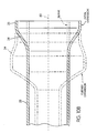
- Fig. 9 shows the tube 28 after further expansion by internal fluid pressure.
- the first section 34 is expanded up to about 100% with the second section 35 slightly expanding or keeping similar expansion levels.
- the second section 35 functioned to accommodate the tube-end engaging blank and to facilitate the expansion of the first section 34.
- the second section 35 may be removed in order to form the reconfigured part 10, as will be further discussed.
- Figs. 10A-10C show the expansion of the tube 28 in its original configuration as a blank, after punching, and after hydroforming in relation to one another. Specifically, Fig. 10A shows the tube 28 prior to expansion in solid lines. Fig. 10B shows the tube 28 after the desired pre-expansion by punching is achieved, in solid lines. Fig. 10C shows the tube 28 after further expansion by internal fluid pressure or hydroforming, in solid lines.
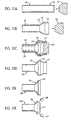
- the illustrated method for expanding the blank 28 includes providing a blank tube 28 (Fig. 11 A) and pre-expanding the first section 34 of the first open end 30 of the tube 28 by axially inserting and then removing the first punch 32 into the first open end 30 of the tube 28 (Fig. 11B).
- the tube 28 is then further expanded with the expansion of the first section 34 of the first open end 30 by providing fluid within the tube 28 and applying fluid pressure to inner surface 29 of the first section of the tube 28 (Fig. 11C).
- a further expanded tube 28 is thus produced (Fig. 11D).
- further expansions and manipulation to the tube 28 can occur.
- the tube 28 can be cut to the specific shape required for the application of the tube 28 as a structural member.
- the first section 34 of the first open end 30 can be cut to the ultimate desired shape or configuration of the part, as for example the reconfigured part 10.
- the second section 35 can be trimmed and cut to length either mechanically or by laser (Fig. 11E).
- the mechanical cutting may include coping.
- additional cutting steps can be performed such as having portions such as in Fig. 11F.
- the sides 58, 60 of the first section 34 are cut to finish the desired trim of the reconfigured part 10 (Fig. 11F).
- the part 10 of the illustrated embodiment after cutting is shown in Fig. 2.
- the open end 14 of the part 10 refers to open end 30 of the tube 28.
- the ear portions 18, 20 correspond to the remaining portions of the first section 34 after cutting.
- the body portion 12 corresponds to the tube 28 after hydroforming.
- Fig. 12 shows the tube after hydroforming with cutting lines shown as dashed lines. It is contemplated that the open end may be cut in multiple ways to obtain different end configurations in order to accommodate different other blanks.
- the tube can be bent prior to expanding the first section. Bending may be done by such methods as mechanically bending or by hydroforming.
- the reconfigured part has a generally rectangular cross-section, it is contemplated that the part may have other configurations, such as circular or other non-circular cross-sections, for example, square or polygonal.
- the second open end may be configured in a similar manner as the first open end.
- the first and second open ends may be initially expanded at the same time and may be further expanded at the same time or the first and second open ends may be initially expanded and further expanded at different times.
- the part 28 can mate with other elements as desired. As illustrated, the part 28 can fully glove the mating part and form an improved joint. This illustrated process can be cost effective relative to other methods of expansion that do not provide the expansion levels as discussed with respect to the illustrated embodiment.
- the punch is also used to seal the end during hydroforming.
- Still another contemplated alternative is to expand the tube according to the illustrated embodiment and then further expand the second section of the tube by utilizing the punch of the '377 application so as to not have to remove the second section.
- joint strength plays a major role in determining tube size and gauge. If the open ends are "super expanded" up to about 100% by the method of the illustrated embodiment described above, the open ends provide a large gloving footprint. As a result, better packaging, reduced mass and cost may be realized.
- Expansion is governed by limitations in material elongation and die friction.
- pre-expanding the tube by a punch before hydroforming, as described above the transition leading up to the reconfigured part is drastically reduced.
- Pushing force may be applied directly to the expansion and growing of the first section of the open ends. Very little tube is contact with the die structure in the expansion area, thus resulting in little friction.
- By keeping the overall reconfigured part relatively square or rectangular the risk of wrinkling is reduced during pushing and draw strains are ensured. The strains introduced into the part during expansion increases the strength of the part.
- super expanded parts 28 are limitless, one contemplated applications for "super expanded" parts for joints in hydroformed motor vehicle frames, such as rear joints in delta engine cradles, front joints in suspension cradles, and cross-blanks.
Landscapes
- Engineering & Computer Science (AREA)
- Mechanical Engineering (AREA)
- Physics & Mathematics (AREA)
- Fluid Mechanics (AREA)
- Shaping Metal By Deep-Drawing, Or The Like (AREA)
Abstract
Claims (15)
- Procédé pour évaser une ébauche tubulaire (28), comportant les étapes consistant à fournir une ébauche tubulaire creuse (28) ayant une première extrémité ouverte (30) avec un axe central (80), et un premier tronçon (34) ayant une surface intérieure avec une coupe transversale fermée s'étendant autour de l'axe central (80) dans une configuration d'origine ;
évaser initialement le premier tronçon (34) de l'ébauche tubulaire (28) en insérant un premier poinçon (32) dans la première extrémité ouverte (30) de l'ébauche tubulaire (28) de telle sorte que la surface intérieure s'évase et se déplace vers l'extérieur, plus loin de l'axe central (80) que dans la configuration d'origine pour former une configuration initialement évasée; et évaser davantage le premier tronçon (34) de l'ébauche tubulaire (28) par hydroformage immédiatement après l'étape consistant à évaser initialement le premier tronçon (34) de l'ébauche tubulaire (28). - Procédé selon la revendication 1, dans lequel le premier tronçon (34) est évasé initialement approximativement 50 % de plus que la configuration d'origine.
- Procédé selon la revendication 1, dans lequel le premier tronçon (34) est évasé davantage approximativement plus de 80 % de plus que la configuration d'origine.
- Procédé selon la revendication 1, dans lequel le premier tronçon (34) est évasé davantage approximativement 100 % de plus que la configuration d'origine.
- Procédé selon la revendication 1, dans lequel l'étape consistant à évaser initialement le premier tronçon (34) comprend l'insertion du poinçon (32) dans la première extrémité ouverte (30) de l'ébauche (28) plusieurs fois.
- Procédé selon la revendication 1, dans lequel l'étape consistant à évaser initialement le premier tronçon (34) comprend l'insertion d'un second poinçon dans la première extrémité ouverte (30) de l'ébauche tubulaire (28) après insertion du premier poinçon (32) dans la première extrémité ouverte (30) de l'ébauche tubulaire (28).
- Procédé selon la revendication 1, comportant en outre l'incurvation de l'ébauche tubulaire avant d'évaser initialement le premier tronçon.
- Procédé selon la revendication 1, comportant en outre la découpe du premier tronçon (34) à une forme ultime.
- Procédé selon la revendication 8, dans lequel la découpe du premier tronçon (34) est réalisée par un laser.
- Procédé selon la revendication 8, dans lequel la première extrémité ouverte (30) a un second tronçon (35), et la découpe du premier tronçon (34) comporte la découpe du second tronçon (35) à une longueur souhaitée et la découpe de côtés du premier tronçon (34) à une forme finie.
- Procédé selon la revendication 1, dans lequel la fourniture de l'ébauche tubulaire creuse (28) comporte la fourniture de l'ébauche tubulaire (28) avec une seconde extrémité ouverte (16) avec un second tronçon ayant une surface intérieure avec une coupe transversale fermée s'étendant autour de l'axe central (80) dans une configuration d'origine ;
évaser initialement le second tronçon de l'ébauche tubulaire en insérant un second poinçon dans la seconde extrémité ouverte de l'ébauche tubulaire de sorte que la surface intérieure s'évase et se déplace vers l'extérieur, plus loin de l'axe central que dans la configuration d'origine pour former une configuration initialement évasée; et
évaser davantage le second tronçon de l'ébauche tubulaire par hydroformage de sorte que la surface intérieure du second tronçon s'évase davantage et se déplace plus loin vers l'extérieur en conformité avec les surfaces de matrice pour former une configuration évasée davantage qui est plus loin de l'axe central (80) que dans la configuration initialement évasée. - Procédé selon la revendication 11, dans lequel les premier et seconde extrémités ouvertes (30, 14 ; 16) sont évasées initialement en même temps.
- Procédé selon la revendication 12, dans lequel les premier et seconde extrémités ouvertes (30, 14 ; 16) sont évasées davantage en même temps.
- Procédé selon la revendication 1, dans lequel l'étape consistant à évaser initialement l'ébauche (28) comporte l'insertion d'un poinçon avec une forme prédéterminée pour configurer une partie terminale de l'extrémité ouverte dans une forme finale.
- Procédé selon la revendication 1, dans lequel ladite étape consistant à évaser davantage le premier tronçon (34) de l'ébauche tubulaire (28), par hydroformage, comporte la mise en place de l'ébauche tubulaire avec la configuration initialement évasée dans une cavité de matrice ayant des surfaces de matrice (54, 56), la fourniture d'un fluide haute pression dans une partie intérieure de l'ébauche (28) de sorte que la surface intérieure du premier tronçon (34) s'évase davantage et se déplace plus loin vers l'extérieur en conformité avec les surfaces de matrice (54, 56) pour former une configuration évasée davantage qui est plus éloignée de l'axe central (80) que dans la configuration initialement évasée.
Applications Claiming Priority (3)
| Application Number | Priority Date | Filing Date | Title |
|---|---|---|---|
| US30265201P | 2001-07-05 | 2001-07-05 | |
| US302652P | 2001-07-05 | ||
| PCT/CA2002/001006 WO2003004190A1 (fr) | 2001-07-05 | 2002-07-04 | Procede d'expansion d'une ebauche tubulaire |
Publications (2)
| Publication Number | Publication Date |
|---|---|
| EP1401596A1 EP1401596A1 (fr) | 2004-03-31 |
| EP1401596B1 true EP1401596B1 (fr) | 2007-04-11 |
Family
ID=23168657
Family Applications (1)
| Application Number | Title | Priority Date | Filing Date |
|---|---|---|---|
| EP02745000A Expired - Lifetime EP1401596B1 (fr) | 2001-07-05 | 2002-07-04 | Procede d'expansion d'une ebauche tubulaire |
Country Status (6)
| Country | Link |
|---|---|
| US (1) | US7013697B2 (fr) |
| EP (1) | EP1401596B1 (fr) |
| CN (1) | CN1313222C (fr) |
| CA (1) | CA2452020C (fr) |
| DE (1) | DE60219470T2 (fr) |
| WO (1) | WO2003004190A1 (fr) |
Cited By (1)
| Publication number | Priority date | Publication date | Assignee | Title |
|---|---|---|---|---|
| DE102008046052A1 (de) | 2008-09-08 | 2010-03-18 | Benteler Automobiltechnik Gmbh | Verfahren zur Herstellung eines rohrförmigen Stabilisators |
Families Citing this family (20)
| Publication number | Priority date | Publication date | Assignee | Title |
|---|---|---|---|---|
| US7827839B2 (en) * | 2002-11-08 | 2010-11-09 | Sumitomo Metal Industries, Ltd. | Profile element pipe for hydraulic bulging, hydraulic bulging device using the element pipe, hydraulic bulging method using the element pipe, and hydraulically bulged product |
| JP4346951B2 (ja) * | 2003-05-08 | 2009-10-21 | 株式会社ベステックスキョーエイ | フューエルインレットの製造方法 |
| ATE399606T1 (de) * | 2004-04-09 | 2008-07-15 | Corus Staal Bv | Verfahren zur innenhochdruckumformung eines rohrförmigen rohlings aus stahl |
| MX2007003351A (es) * | 2004-09-21 | 2008-03-05 | Sumitomo Metal Ind | Tapon, metodo para expandir el diametro interior de un tubo o tuberia de metal utilizando este tapon, metodo para fabricar tubos o tuberia de metal.___________________________________. |
| EP1681110A1 (fr) * | 2005-01-17 | 2006-07-19 | Crown Packaging Technology Inc | Méthode de mise en forme des capsules métalliques ou des corps de boîtier |
| FR2881667B1 (fr) * | 2005-02-10 | 2008-09-12 | Peugeot Citroen Automobiles Sa | Procede permettant d'evaser par deformation chaque extremite d'une barre tubulaire creuse, telle qu'une barre anti-devers d'un train arriere de vehicule automobile |
| US7726165B2 (en) * | 2006-05-16 | 2010-06-01 | Alcoa Inc. | Manufacturing process to produce a necked container |
| US7934410B2 (en) * | 2006-06-26 | 2011-05-03 | Alcoa Inc. | Expanding die and method of shaping containers |
| JP4941054B2 (ja) * | 2007-03-30 | 2012-05-30 | 住友金属工業株式会社 | 継目無ベンド管の製造方法並びに溶接継手及びその製造方法 |
| US8109000B2 (en) * | 2007-05-31 | 2012-02-07 | American Axle & Manufacturing, Inc. | Salisbury axle assembly |
| MY175342A (en) | 2010-08-20 | 2020-06-19 | Alcoa Inc | Shaped metal container and method for making same |
| US8533952B2 (en) * | 2010-12-22 | 2013-09-17 | Nakagawa Sangyo Co., Ltd. | Pipe flange forming method |
| KR20140099480A (ko) * | 2011-11-11 | 2014-08-12 | 애디슨맥키 인크. | 튜브 단부 성형 설비를 위한 서보 모터 제어 유압 펌프 |
| US8910500B2 (en) | 2012-09-10 | 2014-12-16 | National Research Council Of Canada | Low friction end feeding in tube hydroforming |
| US9327338B2 (en) | 2012-12-20 | 2016-05-03 | Alcoa Inc. | Knockout for use while necking a metal container, die system for necking a metal container and method of necking a metal container |
| US20170183920A1 (en) * | 2014-05-07 | 2017-06-29 | Antelope Oil Tool & Mfg. Co., Llc | Collar swaging of single-piece centralizers |
| CN106311857B (zh) * | 2015-12-21 | 2017-11-07 | 青岛世冠装备科技有限公司 | 一种复杂截面中空构件低压镦胀成形方法 |
| FR3072660B1 (fr) * | 2017-10-20 | 2019-11-22 | Ardagh Mp Group Netherlands B.V. | Couvercle pour boite de conserve metallique, comprenant un anneau metallique et membrane pelable thermoscellee |
| KR102613899B1 (ko) * | 2019-02-28 | 2023-12-13 | 제이에프이 스틸 가부시키가이샤 | 금속관의 제조 방법 |
| EP4279194A1 (fr) * | 2022-05-19 | 2023-11-22 | Braun GmbH | Dispositif de soins corporels et procédé de fabrication d'un dispositif de soins corporels |
Family Cites Families (11)
| Publication number | Priority date | Publication date | Assignee | Title |
|---|---|---|---|---|
| US1980264A (en) * | 1932-01-16 | 1934-11-13 | Fulton Sylphon Co | Method of corrugating tubes |
| US3247581A (en) * | 1962-02-05 | 1966-04-26 | Calumet & Hecla | Method of forming a conduit bend |
| GB1370700A (en) * | 1972-03-18 | 1974-10-16 | Gen Motors Ltd | Forming transverse corrugations in a tubular blank |
| JPS5568136A (en) * | 1978-11-15 | 1980-05-22 | Toyota Motor Corp | Pipe end working method and pipe end working device |
| DE3906957A1 (de) * | 1988-12-05 | 1990-09-06 | Kuhn Rainer | Verfahren zur herstellung von rohrartigen bauteilen |
| US5484892A (en) * | 1993-05-21 | 1996-01-16 | Dana-Farber Cancer Institute, Inc. | Monoclonal antibodies that block ligand binding to the CD22 receptor in mature B cells |
| DE4427201C2 (de) * | 1993-11-26 | 1996-09-12 | Ges Innenhochdruckverfahren | Verfahren zur Herstellung von hohlen Nockenwellen |
| DE19882106T1 (de) * | 1997-12-15 | 2000-03-30 | Bestex Kyoei Co | Verfahren zum Ausbilden eines stark gekelchten Rohrs und stark gekelchtes Rohr |
| GB9817112D0 (en) | 1998-08-07 | 1998-10-07 | Gkn Sankey Ltd | A process for forming tubular components |
| US6029487A (en) * | 1998-08-24 | 2000-02-29 | Avmat Kydroforming Ltd. | System and method for manufacturing tubular products from tubular workpieces |
| DE10042465C2 (de) | 2000-08-29 | 2002-08-01 | Vaw Ver Aluminium Werke Ag | Verfahren zum Verformen von rohrförmigen Hohlkörpern aus Metall |
-
2002
- 2002-07-04 CN CNB028132912A patent/CN1313222C/zh not_active Expired - Lifetime
- 2002-07-04 CA CA2452020A patent/CA2452020C/fr not_active Expired - Lifetime
- 2002-07-04 US US10/482,857 patent/US7013697B2/en not_active Expired - Lifetime
- 2002-07-04 WO PCT/CA2002/001006 patent/WO2003004190A1/fr not_active Ceased
- 2002-07-04 DE DE60219470T patent/DE60219470T2/de not_active Expired - Lifetime
- 2002-07-04 EP EP02745000A patent/EP1401596B1/fr not_active Expired - Lifetime
Cited By (2)
| Publication number | Priority date | Publication date | Assignee | Title |
|---|---|---|---|---|
| DE102008046052A1 (de) | 2008-09-08 | 2010-03-18 | Benteler Automobiltechnik Gmbh | Verfahren zur Herstellung eines rohrförmigen Stabilisators |
| DE102008046052B4 (de) * | 2008-09-08 | 2011-10-20 | Benteler Automobiltechnik Gmbh | Verfahren zur Herstellung eines rohrförmigen Stabilisators |
Also Published As
| Publication number | Publication date |
|---|---|
| WO2003004190A1 (fr) | 2003-01-16 |
| CN1313222C (zh) | 2007-05-02 |
| CA2452020C (fr) | 2010-06-29 |
| US7013697B2 (en) | 2006-03-21 |
| CA2452020A1 (fr) | 2003-01-16 |
| US20040231395A1 (en) | 2004-11-25 |
| CN1723093A (zh) | 2006-01-18 |
| DE60219470T2 (de) | 2007-12-13 |
| DE60219470D1 (de) | 2007-05-24 |
| EP1401596A1 (fr) | 2004-03-31 |
Similar Documents
| Publication | Publication Date | Title |
|---|---|---|
| US7013697B2 (en) | Method for expanding a tubular blank | |
| US6739166B1 (en) | Method of forming tubular member with flange | |
| KR100517584B1 (ko) | 하이드로폼 성형된 각진 관형 부품 및 이를 제조하기 위한방법 및 장치 | |
| KR100460691B1 (ko) | 중공몸체의압력성형및천공 | |
| US7360388B2 (en) | Hollow stepped shaft and method of forming the same | |
| EP1377396B1 (fr) | Procede de fabrication de composants structuraux a epaisseur de paroi variable a partir d'ebauches de tubes | |
| EP1210189B1 (fr) | Elements obtenus par hydroformage et procedes de fabrication | |
| MXPA01002003A (es) | Metodo para hidroformar elementos tubulares. | |
| EP1326722B1 (fr) | Appareil et procede d'hydroformage de piece tubulaire | |
| US20030005737A1 (en) | Hydroforming process and apparatus for the same | |
| EP1268097B1 (fr) | Procede de fabrication d' un element tubulaire comprenant un composant de raccord hydroforme | |
| US6826943B2 (en) | Process for forming tube-shaped hollow bodies made of metal | |
| US5941112A (en) | Method and apparatus for hydrotrimming and hydroshearing | |
| CN100551576C (zh) | 形成结构构件的方法 | |
| US7143618B2 (en) | Method of making pre-formed tubular members | |
| JP2832702B2 (ja) | 二重管の製造方法 | |
| US6044678A (en) | Method and device for manufacturing a tubular hollow body with spaced-apart increased diameter portions | |
| US7140226B2 (en) | Methods for making a bicycle frame part having a disproportionally enlarged end section | |
| US6434989B1 (en) | Method and device for producing leadthroughs on hollow profiles | |
| WO1994020234A1 (fr) | Procede de formage d'elements tubulaires | |
| US7431317B2 (en) | Bicycle frame part having a disproportionally enlarged end section and process for making the same | |
| CA2539417A1 (fr) | Procede d'obtention d'un profil creux ferme sur son pourtour | |
| CZ20001228A3 (cs) | Způsob a zařízení pro bezzáhybové hydroformování úhlových trubkových dílů |
Legal Events
| Date | Code | Title | Description |
|---|---|---|---|
| PUAI | Public reference made under article 153(3) epc to a published international application that has entered the european phase |
Free format text: ORIGINAL CODE: 0009012 |
|
| 17P | Request for examination filed |
Effective date: 20031227 |
|
| AK | Designated contracting states |
Kind code of ref document: A1 Designated state(s): AT BE BG CH CY CZ DE DK EE ES FI FR GB GR IE IT LI LU MC NL PT SE SK TR |
|
| AX | Request for extension of the european patent |
Extension state: AL LT LV MK RO SI |
|
| RIN1 | Information on inventor provided before grant (corrected) |
Inventor name: BARBER, MARK, W. |
|
| 17Q | First examination report despatched |
Effective date: 20050324 |
|
| GRAP | Despatch of communication of intention to grant a patent |
Free format text: ORIGINAL CODE: EPIDOSNIGR1 |
|
| GRAS | Grant fee paid |
Free format text: ORIGINAL CODE: EPIDOSNIGR3 |
|
| GRAA | (expected) grant |
Free format text: ORIGINAL CODE: 0009210 |
|
| AK | Designated contracting states |
Kind code of ref document: B1 Designated state(s): DE FR GB |
|
| REG | Reference to a national code |
Ref country code: GB Ref legal event code: FG4D |
|
| REF | Corresponds to: |
Ref document number: 60219470 Country of ref document: DE Date of ref document: 20070524 Kind code of ref document: P |
|
| ET | Fr: translation filed | ||
| PLBE | No opposition filed within time limit |
Free format text: ORIGINAL CODE: 0009261 |
|
| STAA | Information on the status of an ep patent application or granted ep patent |
Free format text: STATUS: NO OPPOSITION FILED WITHIN TIME LIMIT |
|
| 26N | No opposition filed |
Effective date: 20080114 |
|
| REG | Reference to a national code |
Ref country code: FR Ref legal event code: PLFP Year of fee payment: 14 |
|
| REG | Reference to a national code |
Ref country code: FR Ref legal event code: PLFP Year of fee payment: 15 |
|
| REG | Reference to a national code |
Ref country code: DE Ref legal event code: R082 Ref document number: 60219470 Country of ref document: DE Representative=s name: GLAWE DELFS MOLL PARTNERSCHAFT MBB VON PATENT-, DE |
|
| REG | Reference to a national code |
Ref country code: FR Ref legal event code: PLFP Year of fee payment: 16 |
|
| REG | Reference to a national code |
Ref country code: DE Ref legal event code: R082 Ref document number: 60219470 Country of ref document: DE Representative=s name: GLAWE DELFS MOLL PARTNERSCHAFT MBB VON PATENT-, DE Ref country code: DE Ref legal event code: R081 Ref document number: 60219470 Country of ref document: DE Owner name: MAGNA INTERNATIONAL INC., AURORA, CA Free format text: FORMER OWNER: MAGNA STRUCTURAL SYSTEMS INC., AURORA, ONTARIO, CA |
|
| REG | Reference to a national code |
Ref country code: GB Ref legal event code: 732E Free format text: REGISTERED BETWEEN 20180405 AND 20180411 |
|
| REG | Reference to a national code |
Ref country code: FR Ref legal event code: PLFP Year of fee payment: 17 |
|
| REG | Reference to a national code |
Ref country code: FR Ref legal event code: TP Owner name: MAGNA INTERNATIONAL INC., CA Effective date: 20180917 |
|
| PGFP | Annual fee paid to national office [announced via postgrant information from national office to epo] |
Ref country code: GB Payment date: 20180704 Year of fee payment: 17 |
|
| PGFP | Annual fee paid to national office [announced via postgrant information from national office to epo] |
Ref country code: FR Payment date: 20190619 Year of fee payment: 18 |
|
| GBPC | Gb: european patent ceased through non-payment of renewal fee |
Effective date: 20190704 |
|
| PG25 | Lapsed in a contracting state [announced via postgrant information from national office to epo] |
Ref country code: GB Free format text: LAPSE BECAUSE OF NON-PAYMENT OF DUE FEES Effective date: 20190704 |
|
| PG25 | Lapsed in a contracting state [announced via postgrant information from national office to epo] |
Ref country code: FR Free format text: LAPSE BECAUSE OF NON-PAYMENT OF DUE FEES Effective date: 20200731 |
|
| PGFP | Annual fee paid to national office [announced via postgrant information from national office to epo] |
Ref country code: DE Payment date: 20210608 Year of fee payment: 20 |
|
| REG | Reference to a national code |
Ref country code: DE Ref legal event code: R071 Ref document number: 60219470 Country of ref document: DE |