EP1401601B1 - Dispositif de coupe - Google Patents
Dispositif de coupe Download PDFInfo
- Publication number
- EP1401601B1 EP1401601B1 EP02782421A EP02782421A EP1401601B1 EP 1401601 B1 EP1401601 B1 EP 1401601B1 EP 02782421 A EP02782421 A EP 02782421A EP 02782421 A EP02782421 A EP 02782421A EP 1401601 B1 EP1401601 B1 EP 1401601B1
- Authority
- EP
- European Patent Office
- Prior art keywords
- clamping head
- cutting device
- clamping
- workpiece
- tool
- Prior art date
- Legal status (The legal status is an assumption and is not a legal conclusion. Google has not performed a legal analysis and makes no representation as to the accuracy of the status listed.)
- Expired - Lifetime
Links
- 230000000149 penetrating effect Effects 0.000 claims description 2
- 239000011324 bead Substances 0.000 claims 4
- 238000003754 machining Methods 0.000 abstract description 40
- 238000000034 method Methods 0.000 description 9
- 238000009434 installation Methods 0.000 description 5
- 238000010276 construction Methods 0.000 description 3
- 230000035515 penetration Effects 0.000 description 2
- 230000002441 reversible effect Effects 0.000 description 2
- 238000010521 absorption reaction Methods 0.000 description 1
- 230000001419 dependent effect Effects 0.000 description 1
- 238000005192 partition Methods 0.000 description 1
Images

Classifications
-
- B—PERFORMING OPERATIONS; TRANSPORTING
- B23—MACHINE TOOLS; METAL-WORKING NOT OTHERWISE PROVIDED FOR
- B23B—TURNING; BORING
- B23B29/00—Holders for non-rotary cutting tools; Boring bars or boring heads; Accessories for tool holders
- B23B29/04—Tool holders for a single cutting tool
- B23B29/043—Tool holders for a single cutting tool with cutting-off, grooving or profile cutting tools, i.e. blade- or disc-like main cutting parts
-
- B—PERFORMING OPERATIONS; TRANSPORTING
- B23—MACHINE TOOLS; METAL-WORKING NOT OTHERWISE PROVIDED FOR
- B23B—TURNING; BORING
- B23B2205/00—Fixation of cutting inserts in holders
- B23B2205/02—Fixation using an elastically deformable clamping member
-
- Y—GENERAL TAGGING OF NEW TECHNOLOGICAL DEVELOPMENTS; GENERAL TAGGING OF CROSS-SECTIONAL TECHNOLOGIES SPANNING OVER SEVERAL SECTIONS OF THE IPC; TECHNICAL SUBJECTS COVERED BY FORMER USPC CROSS-REFERENCE ART COLLECTIONS [XRACs] AND DIGESTS
- Y10—TECHNICAL SUBJECTS COVERED BY FORMER USPC
- Y10T—TECHNICAL SUBJECTS COVERED BY FORMER US CLASSIFICATION
- Y10T407/00—Cutters, for shaping
- Y10T407/22—Cutters, for shaping including holder having seat for inserted tool
- Y10T407/2272—Cutters, for shaping including holder having seat for inserted tool with separate means to fasten tool to holder
- Y10T407/2282—Cutters, for shaping including holder having seat for inserted tool with separate means to fasten tool to holder including tool holding clamp and clamp actuator
-
- Y—GENERAL TAGGING OF NEW TECHNOLOGICAL DEVELOPMENTS; GENERAL TAGGING OF CROSS-SECTIONAL TECHNOLOGIES SPANNING OVER SEVERAL SECTIONS OF THE IPC; TECHNICAL SUBJECTS COVERED BY FORMER USPC CROSS-REFERENCE ART COLLECTIONS [XRACs] AND DIGESTS
- Y10—TECHNICAL SUBJECTS COVERED BY FORMER USPC
- Y10T—TECHNICAL SUBJECTS COVERED BY FORMER US CLASSIFICATION
- Y10T407/00—Cutters, for shaping
- Y10T407/22—Cutters, for shaping including holder having seat for inserted tool
- Y10T407/2272—Cutters, for shaping including holder having seat for inserted tool with separate means to fasten tool to holder
- Y10T407/2282—Cutters, for shaping including holder having seat for inserted tool with separate means to fasten tool to holder including tool holding clamp and clamp actuator
- Y10T407/2286—Resiliently biased clamp jaw
- Y10T407/2288—Integral with holder
-
- Y—GENERAL TAGGING OF NEW TECHNOLOGICAL DEVELOPMENTS; GENERAL TAGGING OF CROSS-SECTIONAL TECHNOLOGIES SPANNING OVER SEVERAL SECTIONS OF THE IPC; TECHNICAL SUBJECTS COVERED BY FORMER USPC CROSS-REFERENCE ART COLLECTIONS [XRACs] AND DIGESTS
- Y10—TECHNICAL SUBJECTS COVERED BY FORMER USPC
- Y10T—TECHNICAL SUBJECTS COVERED BY FORMER US CLASSIFICATION
- Y10T407/00—Cutters, for shaping
- Y10T407/25—Cutters, for shaping including cut off tool
Definitions
- the invention relates to a cutting device with a holder, according to the feature configuration of the preamble of claim 1.
- the known solutions are used in particular for piercing and longitudinal turning and for parting and separating operations on a rotating workpiece, which is constructed as a rotary member regularly rotationally symmetrical.
- the known cutting devices have an elongate holder with a square cross section, which can be defined over the region of its one free end on a tool holder, wherein a plurality of cutting devices can be accommodated in a holder device and often cramped installation conditions are present.
- the cutting devices can in the overall holder device one above the other, but also directly next to each other lying in line.
- the holder merges integrally into a block-like clamping head, which receives the cutting tool on one side via a receptacle.
- This block-like clamping head has on all sides substantially flat surfaces, which merge into each other at right angles.
- the front side of the clamping head is formed in the form of a straight plane which extends at right angles to the lower and upper sides and the longitudinal sides of the holder. From this surface level forward in the direction of the machining zone is the cutting tool with its cutting edge on and in view of the above-mentioned geometric structure of the clamping head, the cutting edge of the machining tool on the rotating workpiece must first create a space, so for deeper processing of the clamping head on his can follow the entire width.
- FR-A-2 373 349 a generic cutting device with a holder is known, which is provided on a clamping head for receiving a cutting interchangeable tool with a jaw-like receptacle which is arranged on a longitudinal side of the clamping head whose transverse to its longitudinal side extending end face faces a rotating workpiece for the machining, the end face is provided at least in the area in which it opens into the receptacle with a curvature whose curvature corresponds to the curvature of the workpiece with the largest diameter for which the cutting device is provided.
- the curved end face of the clamping head recedes relative to the workpiece to be machined workpiece, and the machining tool is in contrast, recorded in a kind Festlegerippe, in the direction of the machining tool clearly before, so that only in dependence on the width the engageable cutting edge can be given a geometry in the rotating workpiece, for example in the form of an exceptionally narrow in cross-section exception or the like. Due to the curved end face, a space is created in which the rotating workpiece can move, so that basically the clamping head during machining parts of the tool receives and so it is possible that the machining tool has a high penetration depth, without the Clamping head would first be tracked into a free to be machined space of the rotating tool.
- a transverse to the actual nip adjusting gap which emerges from the clamping head upwards into the open.
- the ends of the nip and the adjusting nip respectively ending in the clamping head are disposed adjacent to each other adjacent to each other with the inclusion of a thin partition of the nip head between them.
- the cutting device Due to the additional adjustment gap, which passes through the entire clamping head of the tool transversely to its longitudinal side, the cutting device is based on the force absorption during machining weakened. If the known cutting device in conjunction with other cutting devices in superimposition or juxtaposition in machining engagement with the workpiece, replacement of the worn tool is very difficult due to the unfavorable arrangement of the adjusting screw, which significantly increases the assembly costs for a replacement process.
- the present invention seeks to provide a cutting device of the last-mentioned generic type while maintaining its advantages, namely even narrow geometries in a workpiece machined to a predeterminable depth, without causing collisions between the machining tool and the workpiece , To further improve that a stiffened overall construction is achieved, which can be used easily even in cramped installation situations and in which is reduced even when using multiple holders of cutting devices assembly work for a replacement process of the tool.
- a pertinent object is releasable with cutting devices according to the feature configuration of claim 1.
- the curvature of the front side at the top of the clamping head merges into an oblique flattening, which is penetrated by a clamping gap penetrating the clamping screw, with which the free cross section of the clamping gap can be changed, at least the Passes through clamping head and opens into the receptacle, results for the Clamping screw improved accessibility, whereby the interchangeability of the tool is improved.
- the solution according to the invention comes with only one clamping gap to be set in cross-section. On an additional adjustment gap can be completely dispensed with.
- the solution according to the invention can be readily used even in cramped installation situations, and in particular allows the claimed arrangement of the clamping screw good accessibility of the cutting device for a tool exchange from above, so that can make fast and targeted with little installation work, the replacement process quickly what the downtime significantly reduced.
- the receptacle is part of a fixing rib which protrudes therefrom as an integral part of the clamping head, the curvature of the end face extending from the region of the receptacle to the underside of the clamping head. Due to this fixing rib, however, a stiffened overall construction in the region of the clamping head is obtained, and the forces occurring during the machining can be reliably removed from the cutting edge of the machining tool be derived via this in the locking rib and thus in the other clamping head.
- the nip in the region of its longitudinal side facing away from the receptacle is at least partially penetrated by a counter bearing.
- a counter bearing about the pertinent abutment point ensures that not one side of the clamping process for the machining tool is made, which would possibly lead to tilting, which would ultimately affect the machining accuracy. Rather, it is ensured via the counter bearing that the clamping gap is reduced uniformly, so that no tilting can occur during the setting process of the tool on the fixing rib.
- the curved end face on the underside of the clamping head merges into a supporting surface which extends obliquely to the feed direction of the tool from the receptacle in the direction of the clamping head.
- About the pertinent inclined support surface of the material used for the clamping head is further reduced, and yet the overall construction of the clamping head over the support surface is stiffened so that the machining accuracy is not affected. Since material can be saved in the region of the end face of the clamping head due to the support surface, further space is thus created in the region of the clamping head, which can be utilized by the rotating workpiece during processing, without the risk of collisions.
- the distance between the curved end of the Clamping head and the machining edge of the cutting tool slightly larger than the largest possible diameter of the intended for processing with this tool rotating workpiece.
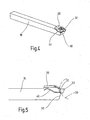
- the cutting device has a holder 10 with a substantially square cross-section.
- the holder 10 has an upper side 12, a lower side 14 and a left and a right longitudinal side 16 and 18 viewed in the machining direction.
- the shaft portion of the holder 10 is formed relatively long, so as to provide a large contact surface for the holder holder (not shown) of a machine tool, such as a lathe (not shown) or the like.
- the holder 10 is provided with a clamping head 20.
- the block-like clamping head 20 passes with its side surfaces to its front side flush in the side surfaces of the holder 10 and is only in the region of the top of the holder 10 with a predetermined projection before.
- the clamping head 20 For receiving a cutting tool 22, the clamping head 20 is provided with a mouth-like receptacle 24, which is arranged in the embodiment shown on the left longitudinal side 16 of the clamping head 20.
- the cutting tool 22 forms in particular a carbide cutting tool with two diametrically opposed cutting edges 26. In the drawing, only the process cutting edge 26 provided for machining is shown, which can be released when worn by opening the mouth-like receptacle 24 of the cutting tool 22. After turning the cutting tool 22 by 180 ° about its transverse axis then the new cutting edge 26 is thereby brought into engagement with the workpiece, that in a further step, the cutting tool 22 via the clamp receptacle 24 again on the clamping head 20 of the holder 10 determines. The pertinent exchange is common, so that at this point will not be discussed in more detail.
- the clamping head 20 has an end face 28, which faces a rotating workpiece 30 (rotating part) in a machining operation.
- the workpiece 30 shown in Figure 3 is to be machined with the cutting device, for example, be exposed from the outside a piercing or longitudinal turning. Furthermore, it should be possible to perform a cutting off operation with the cutting device, in which the machining cutting edge 26, as shown in FIG. 3, up to the longitudinal axis or to the Turning center of the workpiece 30 penetrates, so as to separate parts of the workpiece from the workpiece 30, od in a lathe or the like. On the machine remains.
- the workpiece 30 should have a maximum machining diameter of 20mm.
- the cutting device with its geometric dimensions is then adapted to the machining situation accordingly.
- the underside 14 of the holder 10 extends up to the effective edge of the machining cutting edge 26 over the radius in the machining situation shown there, in which the machining cutting edge 26 has reached the center of the workpiece 30 us the rotary part or workpiece 30, which corresponds to an engagement height of half of the processing diameter, ie 10mm.
- the end face 28 is at least in the area where it merges into the receptacle 24, provided with a curvature 32, the curvature of the curvature of the workpiece 30 with the largest diameter, here 20mm, corresponds, for which the cutting device is provided as a cutting tool 22.
- the receiving 24 is part of a fixing rib 34 of the clamping head 20.
- the pertinent fixing rib 34 in extension of the left side 16 of the holder 10 is thus an integral part of the clamping head 20.
- the curvature 32 of the end face 28 goes to the top 12 of the clamping head 20 in an oblique flattening 36 in the manner of a side surface, which is penetrated by a clamping screw 38, which changes the free cross section of a clamping column 40, which passes through at least the clamping head 20 and in a curved curve with their one Side in the area of the holder 10 ends and opens with its other area to the outside, namely at the curved end face 28.
- the clamping gap 40 is released, and by the inherent elasticity of the material parts of the clamping head 20 gapes the jaw-like receptacle 24th slightly apart and releases the cutting tool 22 for an exchange. In the reverse order, the cutting tool 22 can then be set in the jaw-like clamping receptacle 24 again.
- the distance between the curved end face 28 of the clamping head 20 and the machining edge 26 of the cutting tool 22 is slightly larger than the maximum diameter (20mm) provided for machining with this spanabhe Benden tool 22 rotating Workpiece 30.
- the clamping gap 40 in the region of its longitudinal side facing away from the receptacle 24 (right side 18) is at least partially penetrated by an abutment point 42 which engages in a recess 44 in the clamping head 20 in the manner of a pin. If the clamping screw 38 is tightened for a fixing process, therefore, the upper wall of the clamping gap 40 can be supported on the abutment 42 and the Clamping takes place over the entire width of the cutting tool 22 on the fixing rib 34 can not lead to tilting, which could affect the machining accuracy.
- the clamping gap 40 which projects beyond the clamping head 20 in the direction of the holder 10 in this, thus undergoes a further additional support.
- the curved end face 28 merges on the underside 14 of the clamping head 20 into a support surface 46, which extends at an angle to the feed direction of the cutting tool 22 from the receptacle 24 in the direction of the clamping head 20.
- the pertinent support surface 46 in turn saves material on the clamping head 20, which reduces the risk of collision with the workpiece 30 to be machined.
- the support surface 46 and the curved end face 28 to a stiffening of the fixing rib 34 with the result that despite the low material usage for the clamping head 20, the cutting tool 22 is securely fixed in its receptacle 24, so that the cutting device Can also be used for high-precision machining operations.
- the fixing rib 34 with the cutting tool 22 can also be arranged on the opposite, that is to say in the machining direction on the right-hand side 18.
- a plurality of holders 10 (not shown) with cutting tools 22 may be arranged next to one another in a horizontal plane, in which case two cutting devices arranged adjacent to one another may have the cutting tool 22 once on the left and adjacent to one another on the right side. Also, it is possible to have several of them in a vertical plane To bring cutting devices one above the other in processing arrangement, if machining operations should specify this.
- the curvature 32 of the end face 28 is given only in the region of the height of the receptacle 24, and otherwise the end face 28, as shown in particular in FIG. 5, with a to the bottom 14 receding drainage slope 50 provided.
- the pertinent drainage slope 50 likewise ensures that unwanted collisions between the cutting device and the workpiece 30 can not occur. Since the curvature 32 is realized with its curvature but only partially through the end face 28, it is not possible with the cutting edge 26, as in the solution described above, to the center of the workpiece 30, ie to its axis of rotation to advance.
- the second embodiment is thus provided for special processing situations in which a parting operation, for example, is not mandatory. Nevertheless, it is also possible, without colliding with the workpiece 30, to penetrate far into the workpiece 30 with the cutting tool 22 to produce a narrow machining groove.
- the distance between the curved end face 28 of the clamping head 20 and the machining edge 26 of the cutting tool 22 is slightly larger than the largest possible diameter of the processing for this
- a highly accurate machining can be carried out and it can be very large penetration depths on the workpiece realize without first, as in the prior art, would create corresponding free spaces in the workpiece 30, so that the clamping head 20 can follow the machining direction of the cutting tool 22 in the workpiece 30.
Landscapes
- Engineering & Computer Science (AREA)
- Mechanical Engineering (AREA)
- Cutting Tools, Boring Holders, And Turrets (AREA)
Abstract
Claims (7)
- Dispositif de coupe ayant un élément de retenue (10) qui, sur une tête de serrage (20), est muni, pour loger un outil d'enlèvement de copeaux (22), d'un logement (24) de type mâchoire qui est disposé sur un grand côté (16) de la tête de serrage (20) dont le côté frontal (28), placé transversalement à son grand côté (16), est tourné vers une pièce (30) en rotation pour l'usinage par enlèvement de copeaux, le côté frontal (28) étant, au moins dans la zone dans laquelle il débouche dans le logement (24), muni d'une cambrure (32) dont la courbure correspond à la courbure de la pièce (30) ayant le plus grand diamètre pour laquelle le dispositif de coupe est prévu, caractérisé en ce que la cambrure (32) du côté frontal (28), sur le côté supérieur (12) de la tête de serrage (20), se transforme en un aplatissement (36) disposé obliquement qui est traversé par une vis de serrage (38) pénétrant dans l'interstice de serrage (40), et avec laquelle la section transversale libre de l'interstice de serrage (40) peut être modifiée, interstice qui traverse au moins la tête de serrage (20) et débouche dans le logement (24).
- Dispositif de coupe selon la revendication 1, caractérisé en ce que le logement (24) fait partie d'une nervure de localisation (34) qui, en tant que composante intégrale de la tête de serrage (20), fait saillie à partir de cette dernière, et en ce que la cambrure (32) du côté frontal (28) s'étend depuis la zone du logement (24) jusqu'au côté inférieur (14) de la tête de serrage (20).
- Dispositif de coupe selon une des revendications 1 ou 2, caractérisé en ce que la cambrure (32) du côté frontal (28), avec sa courbure prédéfinie, s'étend sur toute la hauteur de la tête de serrage (20).
- Dispositif de coupe selon une des revendications 1 à 3, caractérisé en ce que l'intervalle entre le côté frontal (28) cambré de la tête de serrage (20) et la lame (26) d'usinage de l'outil d'enlèvement de copeaux (22) est légèrement plus grand que le plus grand diamètre possible de la pièce (30) en rotation prévue pour l'usinage avec cet outil d'enlèvement de copeaux (22).
- Dispositif de coupe selon une des revendications 1 à 4, caractérisé en ce que l'interstice de serrage (40), dans la zone de son grand côté (18) éloigné du logement (24), est traversé au moins partiellement par un emplacement de butée (42).
- Dispositif de coupe selon une des revendications 1 à 5, caractérisé en ce que le côté frontal (28) cambré, sur le côté inférieur (14) de la tête de serrage (20), se transforme en une surface d'appui (46) qui s'étend, obliquement par rapport à la direction d'avance de l'outil d'enlèvement de copeaux (22), depuis le logement (24) en direction de la tête de serrage (20).
- Dispositif de coupe selon une des revendications 1 à 6, caractérisé en ce que l'outil d'enlèvement de copeaux (22) est muni de deux lames (26) actives diamétralement opposées entre elles.
Priority Applications (1)
| Application Number | Priority Date | Filing Date | Title |
|---|---|---|---|
| EP06022369A EP1754561B1 (fr) | 2001-07-05 | 2002-06-18 | Dispositif de coupe |
Applications Claiming Priority (3)
| Application Number | Priority Date | Filing Date | Title |
|---|---|---|---|
| DE10132721A DE10132721C1 (de) | 2001-07-05 | 2001-07-05 | Schneidvorrichtung |
| DE10132721 | 2001-07-05 | ||
| PCT/EP2002/006688 WO2003004203A1 (fr) | 2001-07-05 | 2002-06-18 | Dispositif de coupe |
Related Child Applications (2)
| Application Number | Title | Priority Date | Filing Date |
|---|---|---|---|
| EP06022369A Division EP1754561B1 (fr) | 2001-07-05 | 2002-06-18 | Dispositif de coupe |
| EP06022369.0 Division-Into | 2006-10-26 |
Publications (3)
| Publication Number | Publication Date |
|---|---|
| EP1401601A1 EP1401601A1 (fr) | 2004-03-31 |
| EP1401601B1 true EP1401601B1 (fr) | 2007-06-06 |
| EP1401601B2 EP1401601B2 (fr) | 2011-02-16 |
Family
ID=7690789
Family Applications (2)
| Application Number | Title | Priority Date | Filing Date |
|---|---|---|---|
| EP02782421A Expired - Lifetime EP1401601B2 (fr) | 2001-07-05 | 2002-06-18 | Dispositif de coupe |
| EP06022369A Expired - Lifetime EP1754561B1 (fr) | 2001-07-05 | 2002-06-18 | Dispositif de coupe |
Family Applications After (1)
| Application Number | Title | Priority Date | Filing Date |
|---|---|---|---|
| EP06022369A Expired - Lifetime EP1754561B1 (fr) | 2001-07-05 | 2002-06-18 | Dispositif de coupe |
Country Status (5)
| Country | Link |
|---|---|
| US (1) | US6974283B2 (fr) |
| EP (2) | EP1401601B2 (fr) |
| JP (1) | JP3971377B2 (fr) |
| DE (3) | DE10132721C1 (fr) |
| WO (1) | WO2003004203A1 (fr) |
Families Citing this family (18)
| Publication number | Priority date | Publication date | Assignee | Title |
|---|---|---|---|---|
| US7090585B2 (en) * | 2004-02-27 | 2006-08-15 | Kennametal Inc. | Nail manufacturing tool holder having a quick change mechanism |
| DE102004033929B3 (de) * | 2004-07-14 | 2006-01-12 | SIMTEK Präzisionswerkzeuge GmbH | Werkzeug zur Verwendung in einer Werkzeugmaschine |
| USD525635S1 (en) * | 2005-01-13 | 2006-07-25 | East C Richard | Cutting tooth holder and tooth |
| CN101443146A (zh) * | 2006-02-28 | 2009-05-27 | 钴碳化钨硬质合金公司 | 刀架组件 |
| DE102006035182A1 (de) * | 2006-07-29 | 2008-01-31 | Hartmetall-Werkzeugfabrik Paul Horn Gmbh | Werkzeugsystem |
| DE102006059717A1 (de) | 2006-12-18 | 2008-06-19 | Kennametal Inc. | Werkzeughalter, insbesondere für ein Stechwerkzeug sowie Schneidkörper für einen Werkzeughalter |
| IL198407A (en) * | 2009-04-23 | 2014-01-30 | Iscar Ltd | Cutting tools and cutting tool |
| EP3357610B1 (fr) | 2010-08-04 | 2019-10-09 | CeramTec GmbH | Élément de coupe pour outil de coupe permettant le saignage et le mortaisage |
| DE102011016148B4 (de) | 2011-03-28 | 2024-06-06 | Hartmetall-Werkzeugfabrik Paul Horn Gmbh | Werkzeug zur spanenden Bearbeitung eines Werkstücks mit seitlichem Kühlmittelaustritt und Halter für das Werkzeug |
| DE102011123104B4 (de) | 2011-03-28 | 2024-06-06 | Hartmetall-Werkzeugfabrik Paul Horn Gmbh | Werkzeug zur spanenden Bearbeitung eines Werkstücks mit seitlichem Kühlmittelaustritt |
| DE102011053760A1 (de) | 2011-09-19 | 2013-03-21 | Walter Ag | Stechplatte und Klemmhalter mit Vier-Punktanlagen |
| DE102012004804C5 (de) | 2012-03-09 | 2019-03-14 | Kennametal Inc. | Stechschneidplatte sowie Stechschneidwerkzeug |
| AU2013204785C1 (en) | 2012-07-09 | 2019-09-05 | Fin Control Systems Pty. Limited | Fin Plug for Water Craft |
| AU2013204755A1 (en) | 2012-11-14 | 2014-05-29 | Fin Control Systems Pty. Limited | A Fin Plug for a Water Craft |
| DE102012111240A1 (de) * | 2012-11-21 | 2014-05-22 | Hartmetall-Werkzeugfabrik Paul Horn Gmbh | Spanabhebendes Werkzeug |
| US9579727B2 (en) | 2014-05-28 | 2017-02-28 | Kennametal Inc. | Cutting assembly with cutting insert having enhanced coolant delivery |
| USD778967S1 (en) * | 2015-06-26 | 2017-02-14 | Pengo Corporation | Step shank tooth holder |
| DE102016109327A1 (de) * | 2016-05-20 | 2017-11-23 | Hartmetall-Werkzeugfabrik Paul Horn Gmbh | Halter für ein Werkzeug zur spanenden Bearbeitung, insbesondere für ein Langdrehwerkzeug |
Family Cites Families (31)
| Publication number | Priority date | Publication date | Assignee | Title |
|---|---|---|---|---|
| CH255168A (de) * | 1947-03-29 | 1948-06-15 | Mueller Wirz Albert | Abstechstahl. |
| GB667160A (en) * | 1950-03-13 | 1952-02-27 | Williams & Son Ltd H | An improved tool holder for lathes and other machine tools |
| US3242778A (en) * | 1962-12-05 | 1966-03-29 | Brierley | Machine tools |
| CH535083A (de) * | 1972-06-02 | 1973-03-31 | Angst Fritz | Abstechwerkzeug |
| GB1369096A (en) * | 1972-06-17 | 1974-10-02 | Diagrit Grinding Co Ltd | Cutting tool with removable cutting insert |
| US3894322A (en) * | 1973-05-22 | 1975-07-15 | Iscar Ltd | Holder with interchangeable cutting inserts for machine tools |
| IL48613A0 (en) | 1975-12-08 | 1976-02-29 | Iscar Ltd | Cutting tool providing mounting for interchangeable cutting inserts |
| IT1067034B (it) * | 1976-12-13 | 1985-03-12 | Impero Spa | Utensile a troncare con inserto tagliente |
| JPS5933526Y2 (ja) * | 1979-07-03 | 1984-09-19 | 三菱マテリアル株式会社 | 深切込み用切削工具 |
| DE3219150C3 (de) | 1982-05-21 | 1991-06-13 | Karl Zinner | Stechwerkzeug mit selbstklemmendem schneideinsatz |
| FR2542229B3 (fr) * | 1983-03-07 | 1985-10-31 | Rusch Outillage Precision Sarl | Porte-outils a plaquettes jetables et plaquettes specifiquement concues pour cooperer avec le porte-outils |
| IT8553264U1 (it) * | 1985-04-17 | 1986-10-17 | Iscar Italia S R L | Utensile a piu' funzioni per torni. |
| JPS6211501U (fr) * | 1985-07-08 | 1987-01-24 | ||
| AT388125B (de) * | 1987-07-22 | 1989-05-10 | Plansee Tizit Gmbh | Stechwerkzeug |
| US5273548A (en) * | 1987-12-01 | 1993-12-28 | West Point-Pepperell, Inc. | Method of controlling the shirnkage of garments containing cotton |
| DE8804365U1 (de) * | 1988-03-31 | 1988-05-11 | Kemmer, Klaus, Ing.(grad.), 7277 Wildberg | Schneid- und Abstechwerkzeug |
| DE3823907A1 (de) | 1988-07-14 | 1990-01-18 | Feldmuehle Ag | Klemmhalter fuer rundschneidplatten |
| DE3906822C3 (de) * | 1989-03-03 | 1996-11-21 | Zinner Gmbh Praezisionswerkzeu | Halter für spanabhebende Werkzeug-Einsätze |
| US5267817A (en) * | 1990-12-18 | 1993-12-07 | Sandvik Ab | Cutting tool |
| US5516241A (en) * | 1994-06-27 | 1996-05-14 | Valenite Inc. | Holder blade |
| JP3255802B2 (ja) * | 1994-07-28 | 2002-02-12 | 京セラ株式会社 | 切削インサート |
| SE509594C2 (sv) | 1996-01-26 | 1999-02-15 | Sandvik Ab | Indexering av vändskär |
| AT1323U1 (de) * | 1996-04-18 | 1997-03-25 | Plansee Tizit Gmbh | Schneidwerkzeug mit klemmvorrichtung |
| SE514249C2 (sv) * | 1997-09-10 | 2001-01-29 | Seco Tools Ab | Verktyg för spånavskiljande bearbetning |
| US5921724A (en) * | 1997-12-18 | 1999-07-13 | Kennametal Inc. | Insert and toolholder for machining operations |
| DE19814064C1 (de) * | 1998-03-30 | 1999-05-06 | Horn P Hartmetall Werkzeugfab | Halter für spanabhebende Werkzeug-Einsätze |
| DE19847227C2 (de) | 1998-10-14 | 2001-06-28 | Walter Ag | Zerspanungswerkzeug mit formschlüssigem Plattensitz |
| US6186704B1 (en) * | 1999-03-04 | 2001-02-13 | Kennametal Inc. | Toolholder with detachable blade |
| WO2003024427A1 (fr) * | 1999-12-20 | 2003-03-27 | Temple University Of The Commonwealth System Of Higher Education | Forme posologique orale sous forme de comprime a liberation prolongee |
| IL136564A (en) * | 2000-06-05 | 2003-12-10 | Iscar Ltd | Cutting tool assembly |
| SE522490C2 (sv) | 2001-01-30 | 2004-02-10 | Sandvik Ab | Verktygshållare för skär för spånavskiljande bearbetning med flexibel sidoyta i skärläget |
-
2001
- 2001-07-05 DE DE10132721A patent/DE10132721C1/de not_active Expired - Lifetime
-
2002
- 2002-06-18 WO PCT/EP2002/006688 patent/WO2003004203A1/fr not_active Ceased
- 2002-06-18 JP JP2003510204A patent/JP3971377B2/ja not_active Expired - Fee Related
- 2002-06-18 EP EP02782421A patent/EP1401601B2/fr not_active Expired - Lifetime
- 2002-06-18 US US10/478,318 patent/US6974283B2/en not_active Expired - Lifetime
- 2002-06-18 EP EP06022369A patent/EP1754561B1/fr not_active Expired - Lifetime
- 2002-06-18 DE DE50214754T patent/DE50214754D1/de not_active Expired - Lifetime
- 2002-06-18 DE DE50210280T patent/DE50210280D1/de not_active Expired - Lifetime
Non-Patent Citations (1)
| Title |
|---|
| None * |
Also Published As
| Publication number | Publication date |
|---|---|
| EP1401601A1 (fr) | 2004-03-31 |
| EP1754561B1 (fr) | 2010-11-03 |
| WO2003004203A1 (fr) | 2003-01-16 |
| US6974283B2 (en) | 2005-12-13 |
| JP2004533335A (ja) | 2004-11-04 |
| JP3971377B2 (ja) | 2007-09-05 |
| EP1754561A2 (fr) | 2007-02-21 |
| DE10132721C1 (de) | 2003-01-23 |
| DE50210280D1 (de) | 2007-07-19 |
| EP1754561A3 (fr) | 2007-02-28 |
| DE50214754D1 (de) | 2010-12-16 |
| EP1401601B2 (fr) | 2011-02-16 |
| US20040151551A1 (en) | 2004-08-05 |
Similar Documents
| Publication | Publication Date | Title |
|---|---|---|
| EP1401601B1 (fr) | Dispositif de coupe | |
| EP1087853B1 (fr) | Plaquette de coupe, outil de coupe et procede d'usinage par enlevement de matiere, notamment de surfaces de pieces a symetrie de revolution | |
| EP1321210B1 (fr) | Outil de chanfreinage | |
| DE69300690T2 (de) | Bohrkopf. | |
| EP2229254B1 (fr) | Outil d'alésage de pièces par enlèvement de matière | |
| DD293522A5 (de) | Entgratwerkzeug mit schneidmesser | |
| DE3211766A1 (de) | Schlitzschneider | |
| EP2683510B1 (fr) | Insert de coupe | |
| EP2101943B1 (fr) | Porte-outil, notamment pour un outil de tronçonnage, et élément coupant pour un porte-outil | |
| EP3458214B1 (fr) | Support pour un outil pour usinage, en particulier pour un outil de tournage | |
| DE3432050A1 (de) | Ausdrehwerkzeug mit einem zweischneiderkopf | |
| EP0116260B1 (fr) | Dispositif pour fixer un objet | |
| DE10084868B4 (de) | Rotierendes Schneidwerkzeug mit wechselbarer Schneidplatte | |
| EP1160042B1 (fr) | Alésoir | |
| EP3741483A1 (fr) | Plaquette de coupe, porte-plaquette et dispositif de coupe | |
| DE102004019535A1 (de) | Messerplatte und Werkzeug zur spanenden Bearbeitung von Bohrungsoberflächen | |
| EP2464479B1 (fr) | Outil de fraisage, en particulier outil de fraisage à fileter | |
| EP0162223A1 (fr) | Dispositif de blocage pour plaquettes de coupe | |
| DE29607927U1 (de) | Schneidelement | |
| DE10344481B4 (de) | Vorrichtung zum mechanischen Entfernen von Ablagerungen, insbesondere von Ablagerungen an Schweißelektroden für das Widerstandsschweißen | |
| EP1520647A1 (fr) | Dispositif de reformage d'électrodes et element de coupe de flanc | |
| DE102004008167B4 (de) | Aufbohrwerkzeug | |
| DE3324440C2 (de) | Voll-Bohrer | |
| DE102005014121A1 (de) | Trägerwerkzeug für eine Schneidplatte mit zwei Schneiden und Schneidplatte mit zwei Schneiden | |
| DE9108553U1 (de) | Messerkopf, insbesondere Hobelkopf |
Legal Events
| Date | Code | Title | Description |
|---|---|---|---|
| PUAI | Public reference made under article 153(3) epc to a published international application that has entered the european phase |
Free format text: ORIGINAL CODE: 0009012 |
|
| 17P | Request for examination filed |
Effective date: 20030918 |
|
| AK | Designated contracting states |
Kind code of ref document: A1 Designated state(s): AT BE CH CY DE DK ES FI FR GB GR IE IT LI LU MC NL PT SE TR |
|
| AX | Request for extension of the european patent |
Extension state: AL LT LV MK RO SI |
|
| GRAP | Despatch of communication of intention to grant a patent |
Free format text: ORIGINAL CODE: EPIDOSNIGR1 |
|
| GRAS | Grant fee paid |
Free format text: ORIGINAL CODE: EPIDOSNIGR3 |
|
| GRAA | (expected) grant |
Free format text: ORIGINAL CODE: 0009210 |
|
| AK | Designated contracting states |
Kind code of ref document: B1 Designated state(s): CH DE FR GB IT LI |
|
| REG | Reference to a national code |
Ref country code: GB Ref legal event code: FG4D Free format text: NOT ENGLISH |
|
| GBT | Gb: translation of ep patent filed (gb section 77(6)(a)/1977) |
Effective date: 20070606 |
|
| REG | Reference to a national code |
Ref country code: CH Ref legal event code: NV Representative=s name: ISLER & PEDRAZZINI AG Ref country code: CH Ref legal event code: EP |
|
| REF | Corresponds to: |
Ref document number: 50210280 Country of ref document: DE Date of ref document: 20070719 Kind code of ref document: P |
|
| REG | Reference to a national code |
Ref country code: CH Ref legal event code: PCAR Free format text: ISLER & PEDRAZZINI AG;POSTFACH 1772;8027 ZUERICH (CH) |
|
| ET | Fr: translation filed | ||
| PLBI | Opposition filed |
Free format text: ORIGINAL CODE: 0009260 |
|
| PLAX | Notice of opposition and request to file observation + time limit sent |
Free format text: ORIGINAL CODE: EPIDOSNOBS2 |
|
| 26 | Opposition filed |
Opponent name: ISCAR LTD Effective date: 20080306 |
|
| PLAF | Information modified related to communication of a notice of opposition and request to file observations + time limit |
Free format text: ORIGINAL CODE: EPIDOSCOBS2 |
|
| PLBB | Reply of patent proprietor to notice(s) of opposition received |
Free format text: ORIGINAL CODE: EPIDOSNOBS3 |
|
| APBM | Appeal reference recorded |
Free format text: ORIGINAL CODE: EPIDOSNREFNO |
|
| APBP | Date of receipt of notice of appeal recorded |
Free format text: ORIGINAL CODE: EPIDOSNNOA2O |
|
| APAH | Appeal reference modified |
Free format text: ORIGINAL CODE: EPIDOSCREFNO |
|
| APBU | Appeal procedure closed |
Free format text: ORIGINAL CODE: EPIDOSNNOA9O |
|
| PUAH | Patent maintained in amended form |
Free format text: ORIGINAL CODE: 0009272 |
|
| STAA | Information on the status of an ep patent application or granted ep patent |
Free format text: STATUS: PATENT MAINTAINED AS AMENDED |
|
| 27A | Patent maintained in amended form |
Effective date: 20110216 |
|
| AK | Designated contracting states |
Kind code of ref document: B2 Designated state(s): CH DE FR GB IT LI |
|
| REG | Reference to a national code |
Ref country code: CH Ref legal event code: AEN Free format text: AUFRECHTERHALTUNG DES PATENTES IN GEAENDERTER FORM |
|
| REG | Reference to a national code |
Ref country code: DE Ref legal event code: R102 Ref document number: 50210280 Country of ref document: DE Effective date: 20110216 |
|
| REG | Reference to a national code |
Ref country code: FR Ref legal event code: PLFP Year of fee payment: 15 |
|
| REG | Reference to a national code |
Ref country code: FR Ref legal event code: PLFP Year of fee payment: 16 |
|
| REG | Reference to a national code |
Ref country code: FR Ref legal event code: PLFP Year of fee payment: 17 |
|
| PGFP | Annual fee paid to national office [announced via postgrant information from national office to epo] |
Ref country code: FR Payment date: 20210622 Year of fee payment: 20 Ref country code: IT Payment date: 20210625 Year of fee payment: 20 |
|
| PGFP | Annual fee paid to national office [announced via postgrant information from national office to epo] |
Ref country code: GB Payment date: 20210625 Year of fee payment: 20 Ref country code: CH Payment date: 20210618 Year of fee payment: 20 |
|
| PGFP | Annual fee paid to national office [announced via postgrant information from national office to epo] |
Ref country code: DE Payment date: 20210727 Year of fee payment: 20 |
|
| REG | Reference to a national code |
Ref country code: DE Ref legal event code: R071 Ref document number: 50210280 Country of ref document: DE |
|
| REG | Reference to a national code |
Ref country code: CH Ref legal event code: PL |
|
| REG | Reference to a national code |
Ref country code: GB Ref legal event code: PE20 Expiry date: 20220617 |
|
| PG25 | Lapsed in a contracting state [announced via postgrant information from national office to epo] |
Ref country code: GB Free format text: LAPSE BECAUSE OF EXPIRATION OF PROTECTION Effective date: 20220617 |