EP1402247B1 - Vorrichtung und analyseverfahren zur feuchtigkeitsbestimmung in materialien - Google Patents
Vorrichtung und analyseverfahren zur feuchtigkeitsbestimmung in materialien Download PDFInfo
- Publication number
- EP1402247B1 EP1402247B1 EP02742535A EP02742535A EP1402247B1 EP 1402247 B1 EP1402247 B1 EP 1402247B1 EP 02742535 A EP02742535 A EP 02742535A EP 02742535 A EP02742535 A EP 02742535A EP 1402247 B1 EP1402247 B1 EP 1402247B1
- Authority
- EP
- European Patent Office
- Prior art keywords
- moisture content
- coefficients
- frequency
- phase shift
- sub
- Prior art date
- Legal status (The legal status is an assumption and is not a legal conclusion. Google has not performed a legal analysis and makes no representation as to the accuracy of the status listed.)
- Expired - Lifetime
Links
- 239000000463 material Substances 0.000 title claims abstract description 47
- 238000004458 analytical method Methods 0.000 title description 3
- 238000000034 method Methods 0.000 claims abstract description 73
- 230000010363 phase shift Effects 0.000 claims abstract description 37
- 230000001131 transforming effect Effects 0.000 claims abstract 3
- 230000009466 transformation Effects 0.000 claims description 9
- 239000006185 dispersion Substances 0.000 claims description 5
- 238000000844 transformation Methods 0.000 claims description 3
- 238000005259 measurement Methods 0.000 description 35
- 230000005540 biological transmission Effects 0.000 description 10
- 239000000523 sample Substances 0.000 description 9
- 230000009467 reduction Effects 0.000 description 8
- 238000012937 correction Methods 0.000 description 6
- 230000001419 dependent effect Effects 0.000 description 5
- 230000000694 effects Effects 0.000 description 5
- 230000008901 benefit Effects 0.000 description 3
- 230000000875 corresponding effect Effects 0.000 description 3
- 229910052500 inorganic mineral Inorganic materials 0.000 description 3
- 239000011707 mineral Substances 0.000 description 3
- 230000004044 response Effects 0.000 description 3
- 230000001629 suppression Effects 0.000 description 3
- 239000003245 coal Substances 0.000 description 2
- 230000009977 dual effect Effects 0.000 description 2
- 239000000696 magnetic material Substances 0.000 description 2
- 238000004519 manufacturing process Methods 0.000 description 2
- 230000008569 process Effects 0.000 description 2
- 230000000644 propagated effect Effects 0.000 description 2
- 238000003491 array Methods 0.000 description 1
- 238000013528 artificial neural network Methods 0.000 description 1
- 239000002802 bituminous coal Substances 0.000 description 1
- 230000008859 change Effects 0.000 description 1
- 238000006243 chemical reaction Methods 0.000 description 1
- 239000012141 concentrate Substances 0.000 description 1
- 238000007796 conventional method Methods 0.000 description 1
- 230000002596 correlated effect Effects 0.000 description 1
- 238000010586 diagram Methods 0.000 description 1
- 238000005516 engineering process Methods 0.000 description 1
- 238000002474 experimental method Methods 0.000 description 1
- 238000009472 formulation Methods 0.000 description 1
- 239000007789 gas Substances 0.000 description 1
- 238000007429 general method Methods 0.000 description 1
- 230000006872 improvement Effects 0.000 description 1
- 230000003993 interaction Effects 0.000 description 1
- 238000011545 laboratory measurement Methods 0.000 description 1
- 238000012417 linear regression Methods 0.000 description 1
- 239000000203 mixture Substances 0.000 description 1
- 239000003921 oil Substances 0.000 description 1
- 238000002310 reflectometry Methods 0.000 description 1
- 238000005070 sampling Methods 0.000 description 1
- 230000035945 sensitivity Effects 0.000 description 1
- 239000000126 substance Substances 0.000 description 1
- 238000010408 sweeping Methods 0.000 description 1
- 230000009897 systematic effect Effects 0.000 description 1
- XLYOFNOQVPJJNP-UHFFFAOYSA-N water Substances O XLYOFNOQVPJJNP-UHFFFAOYSA-N 0.000 description 1
Images

Classifications
-
- G—PHYSICS
- G01—MEASURING; TESTING
- G01N—INVESTIGATING OR ANALYSING MATERIALS BY DETERMINING THEIR CHEMICAL OR PHYSICAL PROPERTIES
- G01N22/00—Investigating or analysing materials by the use of microwaves or radio waves, i.e. electromagnetic waves with a wavelength of one millimetre or more
- G01N22/04—Investigating moisture content
Definitions
- the present invention relates to a method and apparatus for determining the moisture content of materials.
- Moisture content is a key production parameter in many processes.
- Materials of interest are wide ranging and include food-stuffs, chemicals, mineral ores, mineral concentrates, coal, oil and gas.
- electromagnetic wave interaction with the material of interest may provide a method for moisture determination.
- Microwave-based methods rely on the observed high correlation between moisture content and either one or more of the parameters of wave phase shift, reflectance or attenuation. This correlation exists for a wide range of materials. Fundamentally the correlation occurs because unbounded water exhibits a dielectric constant with a very large magnitude compared to the material in which it is entrained.
- the effective dielectric constant may be derived from the dielectric tensor, which is the most general physical quantity that describes wave dispersion in all types of linear media, both magnetic and non-magnetic.
- the non-magnetic material response is dependent on both real and imaginary parts of the effective dielectric constant.
- the phase shift and reflectivity is usually mostly affected by the real part for typical materials of interest, while attenuation is more dependent on both real and imaginary parts. Similar considerations apply for magnetic materials, so long as the magnetic response remains somewhat weaker than the dielectric response imparted by the presence of free moisture.
- Microwave methods may generally be divided between different classes of measurement. For example, measurements may employ the apparatus of tuned microwave resonant cavities. Another class of measurement involves free space measurements. In free space measurements radiating structures (antennas) launch electromagnetic waves which are transmitted without the use of any guiding structure towards the material of interest. Free space methods have the general advantage that the apparatus does not constrain the flow of material in any way, which may be important in industrial processes. Free space measurements themselves may be generally subdivided between transmission and reflection measurements.
- the wave reflected off an air-material interface is measured.
- This wave may be received by the same structure that is used to transmit the wave, or with alternative receiving antennas.
- the amplitude and phase of the reflected wave is correlated in some way to the moisture content.
- phase shift and attenuation of the wave through the material may serve as the basic variable used to estimate moisture content, although phase shift generally demonstrates the better correlation to moisture content.
- phase shift and attenuation are also generally dependent on both the density and thickness of the material.
- phase shift varies most linearly with the quantity defined by material mass per unit area (MPUA) presented to the transmitted wave.
- MPUA material mass per unit area
- an auxiliary or normalising parameter approximating MPUA is usually required to compensate for these variations.
- MPUA may be approximated by either of the parameters of material height or mass loading.
- the auxiliary parameter is used to provide a weighting parameter to normalise the wave phase shift before moisture is inferred from the measurement. Where significant non-linearities exist between the weighting parameter and MPUA this will increase error in the estimated moisture content.
- phase shift imparted by the material is often limited to materials that do not change markedly in presentation or moisture content. This fact limits the utility of single frequency measurements.
- Presently the state of the art in transmission measurements is to employ multi-frequency methods.
- multi-frequency method There are several classes of multi-frequency method.
- One class employs two (dual) discrete frequencies separated by a modest frequency range (high frequency approximately 1.05 to 2 times the lower frequency).
- Another class employs a multitude of discrete frequencies or a continuum of frequencies within a frequency band; these may generally be regarded as "swept" frequency methods.
- Yet another class may employ electromagnetic wave pulses (in this case the finite length of the pulse implicitly defines the frequency band that is used by the generation of sidebands). In all cases the information carried in extra frequency components is used to resolve the absolute phase shift beyond 360 degrees.
- US6249129 discloses a method and an apparatus for determining the moisture content in a sample by measuring the phase shift of transmitted microwaves at a plurality of frequencies.
- the frequencies vary over a range of 2.7 to 3.4 GHz and the length of the transmission path is 40 millimeter.
- a straight compensation line is fitted by linear regression to these phase/frequency points and the value of the compensation line at the center frequency is used as the corrected phase shift to determine the moisture content.
- Miljak, Cutmore et al.: "LOW COST MICROWAVE MOISTURE ANALYSER FOR THE MINERALS AND PROCESS INDUSTRIES” discloses a moisture analyser, which operates in the frequency range 1-2 GHz. Operation is restricted to two discrete frequencies separated by 30 % or so, operating simultaneously and continuously. While this reduces the total information available for the phase unwrapping, it significantly reduces the hardware overhead with regard to sweeping the frequency.
- the frequency range is sufficiently high so as to enable the use of antenna arrays of workable size with reasonable directivity, and at the same time provides fairly low phase shifts that can be easily unwrapped.
- the analyser adopts a modern modulation scheme using the general methods of up and down-conversion adapted for measurement of carrier phase.
- Error in transmission measurements may derive from a number of sources.
- One source of error is the reception of spurious waves with phase that may be unrelated or weakly related to the moisture in the material. Such spurious waves include waves reaching the receiver that have not passed through the material (or only a small section of material), and waves which pass several times through the material by way of multiple reflections. These spurious waves act to distort the measured phase in all types of transmission measurements.
- Another source of error may be from limitations in the receiver itself. For example the receiver may loose sensitivity at high attenuation, resulting in the measurement of phase that is not a true representation of the actual received wave phase.
- the invention provides a method of estimating moisture content in a material as defined in claim 1.
- the step of estimating moisture content in a material involves the features of dependent claims 2-11.
- the present invention also provides an apparatus for estimating moisture content in a material, as defined in claim 12.
- the preferred embodiment of the present invention is a method which employs a dual discrete frequency free space transmission apparatus that is used to measure continuously the phase shifts and attenuations of electromagnetic waves at each frequency that are propagated through the material of interest.
- the preferred embodiment exploits the discovery of an analysis technique, hereafter referred to as method (I), involving the use of two measured phases that provides a superior accuracy of moisture measurement. Specifically, a transformation involving two absolute phases is used to calculate a correction so as to obtain a more accurate absolute phase shift by reducing the effect of spurious waves and receiver errors.
- method (II) a compensation technique, henceforth known as method (II), during device calibration to improve measurement accuracy.
- This method (11) method is used to reduce distortions in an auxiliary weighting parameter (described above) required to normalise the measured phase shift.
- the apparatus in this particular configuration specifically aids the implementation of method (I) through the high accuracy of phase measurement provided by this configuration. With inferior phase accuracy the error in moisture estimates is generally increased. In turn, the error reduction afforded by method (I) is reduced. While method (I) can be used with other apparatus, the value of method (I) is fully utilised and overall performance of the apparatus is enhanced if systematic and random phase errors related to the microwave receive circuitry are reduced.
- FIG. 3 An example of a preferred configuration of the apparatus used to implement the high accuracy phase measurement scheme is shown in block diagram form in Figure 3 , where one channel of the transmit-receive system is shown.
- the device would normally have two transmit-receive channels at separate frequencies, each operating continuously.
- Modulating signals, together with the carrier at microwave frequency, are applied to a quadrature modulator 1.
- the modulating frequency may lie anywhere between audio and high frequency radio bands. Two waves at microwave frequency are therefore available to the channel; the original carrier and the output of the quadrature modulator.
- One of these waves may be propagated through the material (probe wave) after being launched from a transmitting antenna 2, while the other may be used as a local oscillator in a receiver subsystem 3.
- the probe wave Upon reception of the probe wave by a receiving antenna 4, the probe wave is fed to the low-noise demodulating receiver 5. A component of the receiver output will be in the same frequency band as the modulating signals. This output wave may be compared to one of the modulating signals (either serving as a possible reference wave) in order to determine phase shift and attenuation imparted to the microwave probe wave. A direct reading of the phase and amplitude is provided using a phase comparator and a logarithmic demodulator 6. In general, accuracy of the method depends on the amount of suppression of unwanted sidebands generated by the modulator. Generally quadrature modulators have imperfections that produce small but non-zero unwanted sidebands.
- ⁇ 1 and ⁇ 2 be the absolute phase shifts measured at the two respective discrete frequencies f 1 and f 2 .
- the absolute phases are calculated from the measured phases using methods known to persons skilled in the art.
- the parameter ⁇ is a fixed constant with a value suitably chosen so as to reduce measurement error.
- ⁇ is a fixed constant with a value suitably chosen so as to reduce measurement error.
- the reduction in measurement error afforded by the transformation defined by equation (1) also depends on the distribution of phase errors.
- the subscript i denotes sample number.
- the method is aided by operating at low frequency so that the parameter K is often very near unity for many materials; this allows application of the method without recourse to complicated measurements to determine K . Furthermore the simultaneous measurement of the wave phase and amplitude at two frequencies and sufficiently high accuracy delivered by the apparatus is required for proper application of method (I).
- the technique of compensation applies to an external weighting signal w that is usually provided to normalise corrected phase, e.g., conveyer mass loading cell, mass flow meters in pipes etc.
- normalise corrected phase e.g., conveyer mass loading cell, mass flow meters in pipes etc.
- MPUA material mass per unit area
- the auxiliary parameter w is used indirectly to infer relative MPUA.
- the technique described here may be used to remove to some extent the non-linearity that often exists between the parameter w and the material MPUA.
- calibration data is available where the pair of variables ( ⁇ , w ) are the corrected phase and weighting variable respectively, and M the corresponding actual moisture measured through some means, for example manual sampling.
- a one to one correspondence between M and M * is therefore defined for each value of ( ⁇ , w ).
- the quality of this regression may be defined by the standard deviation of differences between M and M * defined for each ( ⁇ , w ). This quantity may be denoted as the standard error.
- the first set of coefficients B are determined by a multi-dimensional non-linear minimisation scheme, e.g. the Nelder-Mead downhill simplex method, although any suitable minimisation scheme will suffice.
- the second set C and therefore the standard error of the regression is determined by the usual known least squares method described above.
- the standard error is the variable that is the object of minimisation.
- the multi-dimensional scheme is used to search the parameter space spanned by the first coefficient set B in order to find the optimal first set B that minimises the standard error.
- the second set C corresponding to the optimum is determined simultaneously and, if significant non-linearity exists between w and MPUA, the first and second sets B and C together describe a regression with a reduced standard error compared to that which would be obtained without the introduction of the first set B .
- the function G must be chosen to adequately simulate the non-linearity in w in order to reduce the standard error.
- Compensation method (II) provides a fitting technique that removes non-linearity between the parameter w and MPUA. This formulation of a non-linear fitting method is straightforward, avoids strong redundancies between coefficients and has the advantage of transparency compared to the usual application of say, neural networks. The method can be performed off-line during measured calibration or may be implemented on-line in special circumstances where calibration data may be available to the device on-line
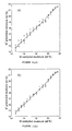
- Method (I) has been applied to a set of phase data measured in the laboratory for semi-bituminous coal for thickness spanning the range between 200-400mm and moisture in the range 14.5-21.5wt.%.
- Figure 1(a) shows the regression obtained by fitting a quadratic between sampled moisture data M and ⁇ , where ⁇ is the phase at high frequency normalised to the material mass.
- the sample mass is a good estimator of mass per unit area, since in the experiment the material filled a container of fixed cross sectional dimension.
- the standard error of the fit is 0.27wt.% while the correlation coefficient is 0.990.
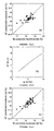
- Method (II) was applied to data collected in an on-line application.
- a calibration consisting of a set containing 37 points was available to the method.
- ⁇ is the absolute phase
- w a normalising parameter, in this case derived from a beltweigher.
- the variation in w over the calibration set was sufficient to merit use of method (II).
- the regression resulting without application of method (II) is shown in figure 2(a) .
Landscapes
- Physics & Mathematics (AREA)
- Biochemistry (AREA)
- General Physics & Mathematics (AREA)
- Life Sciences & Earth Sciences (AREA)
- Chemical & Material Sciences (AREA)
- Analytical Chemistry (AREA)
- Electromagnetism (AREA)
- General Health & Medical Sciences (AREA)
- Health & Medical Sciences (AREA)
- Immunology (AREA)
- Pathology (AREA)
- Investigating Or Analysing Materials By Optical Means (AREA)
- Investigating Or Analyzing Materials By The Use Of Electric Means (AREA)
- Sampling And Sample Adjustment (AREA)
- Investigating Or Analyzing Non-Biological Materials By The Use Of Chemical Means (AREA)
Claims (13)
- Ein Verfahren zum Schätzen eines Feuchtigkeitsgehalts in einem Material, das folgende Schritte aufweist:Leiten eines ersten Frequenzsignals (f1) und eines zweiten Frequenzsignals (f2) durch ein Material, wobei f1 und f2 beide im Bereich von 0,5 bis 2,0 GHz liegen;Bestimmen einer ersten absoluten Phasenverschiebung (Φ1) des ersten Frequenzsignals und einer zweiten absoluten Phasenverschiebung (Φ2) des zweiten Frequenzsignals, wobei die absoluten Phasenverschiebungen mehr als 360 Grad aufgelöst sind;Transformieren von Φ1 in eine erste korrigierte absolute Phasenverschiebung (Φ1c) und von Φ2 in eine zweite korrigierte absolute Phasenverschiebung (Φ2c), unter Verwendung der folgenden Transformationen:wobei γ = K·f1/ f2 ≠ 1 und K eine Konstante ist, die eine Dispersion des Materials mit den zwei Frequenzen berücksichtigt, und wobei die Frequenzen f1 und f2 so gewählt sind, dass K nahe 1,0 ist; und


Schätzen des Feuchtigkeitsgehalts aus zumindest entweder Φ1c oder Φ2c. - Ein Verfahren gemäß Anspruch 1, bei dem der Schritt des Schätzens des Feuchtigkeitsgehalts unter Verwendung einer ersten und zweiten Modellierungsfunktion mit bestimmen Werten eines ersten und zweiten Satzes von Koeffizienten durchgeführt wird, die durch Folgende erhalten werden:(a) Erhalten von Messdaten einschließlich korrigierter Phasendaten, tatsächlicher Feuchtigkeitsgehaltsdaten und Gewichtungsdaten, wobei die Gewichtungsdaten die Materialmasse pro Einheitsfläche des Materials, für das ein Feuchtigkeitsgehalt geschätzt werden soll, darstellen;(b) Einrichten einer ersten Modellierungsfunktion, um jegliche Nichtlinearität in den Gewichtungsdaten zu modellieren, wobei die erste Modellierungsfunktion einen ersten Satz von Koeffizienten aufweist;(c) Einrichten einer zweiten Modellierungsfunktion, die einen geschätzten Feuchtigkeitsgehalt zu einer korrigierten Phase und der ersten Modellierungsfunktion in Beziehung setzt, wobei die zweite Modellierungsfunktion einen zweiten Satz von Koeffizienten aufweist; und(d) Bestimmen von Werten des ersten und zweiten Satzes von Koeffizienten, die einen Fehler zwischen einem geschätzten Feuchtigkeitsgehalt und einem tatsächlichen Feuchtigkeitsgehalt für die Messdaten minimieren.
- Ein Verfahren gemäß Anspruch 2, bei dem der Schritt (d) Folgendes betrifft:(i) Bestimmen einer Mehrzahl von Sätzen von Versuchswerten für den ersten Satz von Koeffizienten;(ii) Durchführen einer Regression, um Werte des zweiten Satzes von Koeffizienten zu bestimmen, die für jeden Satz von Versuchswerten einen Fehler minimieren; und(iii) Bestimmen, welcher Satz von Versuchswerten einen Fehler minimiert.
- Ein Verfahren gemäß Anspruch 3, bei dem Schritt (d)(i) unter Verwendung eines nichtlinearen Minimierungsschemas durchgeführt wird.
- Ein Verfahren gemäß Anspruch 4, bei dem das nichtlineare Minimierungsschema das Downhill-Simplex-Verfahren nach Nelder-Mead ist.
- Ein Verfahren gemäß einem der Ansprüche 2 bis 5, bei dem die erste Modellierungsfunktion in der Form ω* = G(w,B) vorliegt, wobei ω* die modellierte Gewichtung ist, w die tatsächliche Gewichtung ist und B den ersten Satz von Koeffizienten darstellt.
- Ein Verfahren gemäß Anspruch 6, bei dem G(ω,B) gewählt ist, um eine Nichtlinearität in ω möglichst genau zu modellieren.
- Ein Verfahren gemäß Anspruch 6, bei dem G(ω,B) gleich b1 + b2 + b2ω + b3ω2 sein kann, wo der erste Satz von Koeffizienten B = {b1, b2, b3} ist.
- Ein Verfahren gemäß einem der Ansprüche 2 bis 8, bei dem die zweite Modellierungsfunktion ein Satz von Funktionen in der Form

ist, wobei M* ein geschätzter Feuchtigkeitsgehalt ist, Ci einen Satz von n zweiten Koeffizienten darstellt und Fi einen Satz von Funktionen darstellt. - Ein Verfahren gemäß Anspruch 9, bei dem der Satz von Funktionen Fi Funktionen einer korrigierten Phase (Φ) und der ersten Modellierungsfunktion ω* ist.
- Ein Verfahren gemäß Anspruch 10, bei dem n = 3 und F(φ,ω*) =

- Vorrichtung zum Schätzen eines Feuchtigkeitsgehalts in einem Material, die folgende Merkmale aufweist:einen Sender zum Leiten eines ersten Frequenzsignals (f1) und eines zweiten Frequenzsignals (f2) durch ein Material, wobei f1 und f2 beide in dem Bereich von 0,5 bis 2,0 GHz liegen;einen Empfänger zum Empfangen des ersten und zweiten Frequenzsignals;eine Bestimmungseinrichtung zum Bestimmen einer ersten absoluten Phasenverschiebung (Φ1) des ersten Frequenzsignals und einer zweiten absoluten Phasenverschiebung (Φ2) des zweiten Frequenzsignals, wobei die absoluten Phasenverschiebungen mehr als 360 Grad aufgelöst sind;eine Transformationseinrichtung zum Transformieren von Φ1 in eine erste korrigierte absolute Phasenverschiebung (Φ1c) und Φ2 in eine zweite korrigierte absolute Phasenverschiebung (Φ2c), unter Verwendung der folgenden Transformationen:wobei γ = K · f1 / f2 ≠ 1 und K eine Konstante ist, die eine Dispersion des Materials mit den zwei Frequenzen berücksichtigt, und wobei die Frequenzen f1 und f2 so gewählt sind, dass K nahe 1,0 ist; und


eine Feuchtigkeitsgehaltschätzeinrichtung zum Schätzen eines Feuchtigkeitsgehalts aus zumindest entweder Φ1c oder Φ2c. - Vorrichtung gemäß Anspruch 12, bei der die Feuchtigkeitsgehaltschätzeinrichtung durch Folgende kalibriert ist:(a) Erhalten von Messdaten einschließlich korrigierter Phasendaten, tatsächlicher Feuchtigkeitsgehaltsdaten und Gewichtungsdaten, wobei die Gewichtungsdaten die Materialmasse pro Einheitsfläche des Materials, für das ein Feuchtigkeitsgehalt geschätzt werden soll, darstellen;(b) Einrichten einer ersten Modellierungsfunktion, um jegliche Nichtlinearität in den Gewichtungsdaten zu modellieren, wobei die erste Modellierungsfunktion einen ersten Satz von Koeffizienten aufweist; und(c) Einrichten einer zweiten Modellierungsfunktion, die einen geschätzten Feuchtigkeitsgehalt zu einer gemessenen Phase und der ersten Modellierungsfunktion in Beziehung setzt, wobei die zweite Modellierungsfunktion einen zweiten Satz von Koeffizienten aufweist; und(d) Bestimmen von Werten des ersten und zweiten Satzes von Koeffizienten, die einen Fehler zwischen einem geschätzten Feuchtigkeitsgehalt und einem tatsächlichen Feuchtigkeitsgehalt für die Messdaten minimieren,wobei die Schätzeinrichtung einen Feuchtigkeitsgehalt unter Verwendung der ersten und zweiten Modellierungsfunktion mit den bestimmten Werten des ersten und zweiten Satzes von Koeffizienten schätzen kann.
Applications Claiming Priority (3)
| Application Number | Priority Date | Filing Date | Title |
|---|---|---|---|
| AUPR611101 | 2001-07-04 | ||
| AUPR6111A AUPR611101A0 (en) | 2001-07-04 | 2001-07-04 | Apparatus and analysis method for determination of moisture in materials |
| PCT/AU2002/000902 WO2003005008A1 (en) | 2001-07-04 | 2002-07-04 | Apparatus and analysis method for determination of moisture in materials |
Publications (3)
| Publication Number | Publication Date |
|---|---|
| EP1402247A1 EP1402247A1 (de) | 2004-03-31 |
| EP1402247A4 EP1402247A4 (de) | 2005-10-19 |
| EP1402247B1 true EP1402247B1 (de) | 2008-05-14 |
Family
ID=3830075
Family Applications (1)
| Application Number | Title | Priority Date | Filing Date |
|---|---|---|---|
| EP02742535A Expired - Lifetime EP1402247B1 (de) | 2001-07-04 | 2002-07-04 | Vorrichtung und analyseverfahren zur feuchtigkeitsbestimmung in materialien |
Country Status (8)
| Country | Link |
|---|---|
| US (1) | US7031862B2 (de) |
| EP (1) | EP1402247B1 (de) |
| CN (1) | CN1300574C (de) |
| AT (1) | ATE395588T1 (de) |
| AU (1) | AUPR611101A0 (de) |
| CA (1) | CA2448904C (de) |
| DE (1) | DE60226602D1 (de) |
| WO (1) | WO2003005008A1 (de) |
Families Citing this family (14)
| Publication number | Priority date | Publication date | Assignee | Title |
|---|---|---|---|---|
| FR2880121B1 (fr) * | 2004-12-23 | 2007-02-23 | Inst Francais Du Petrole | Methode pour determiner la composition d'un fluide polyphasique |
| US7836910B2 (en) * | 2004-12-29 | 2010-11-23 | Rain Bird Corporation | Soil moisture sensor and controller |
| DE102006013726A1 (de) * | 2006-03-24 | 2007-09-27 | Bartec Gmbh | Verfahren und Sensor zum Bestimmen des Kohlenwasserstoff-Taupunktes in einem Gas |
| MD3713G2 (ro) * | 2008-05-19 | 2009-04-30 | Институт Химии Академии Наук Молдовы | Metodă de determinare a domeniului normal de variaţie a echilibrului hidric |
| CN101706459B (zh) * | 2009-02-01 | 2013-05-01 | 杨厚荣 | 一种微波雷达水份传感器 |
| DE102010041571B4 (de) * | 2010-09-28 | 2012-11-22 | Hauni Maschinenbau Ag | Vorrichtung und Verfahren zur Verarbeitung und Messung von Eigenschaften eines bewegten Materialstrangs |
| CN105510386A (zh) * | 2014-09-26 | 2016-04-20 | 多瑙控制治理工程有限责任公司 | 用于测量纸和各种含纤维材料的含水量的射频测量系统 |
| CN105090751A (zh) * | 2015-08-31 | 2015-11-25 | 无锡伊佩克科技有限公司 | 一种自给型输油管含水量检测及控制系统 |
| CN105116932A (zh) * | 2015-08-31 | 2015-12-02 | 无锡伊佩克科技有限公司 | 一种输油管含水量监控预警系统 |
| CN107238611A (zh) * | 2017-06-05 | 2017-10-10 | 默斯测控技术(长沙)有限公司 | 含水量分析方法、装置以及水分测量仪及测量方法 |
| EP3674703A1 (de) * | 2018-12-31 | 2020-07-01 | INESC TEC - Instituto de Engenharia de Sistemas e Computadores, Tecnologia e Ciência | Verfahren und vorrichtung zur messung von in vegetation vorhandenem wasser |
| CN112798622B (zh) * | 2021-01-04 | 2022-05-17 | 电子科技大学 | 一种基于微波透射原理的木材含水率检测装置及方法 |
| CN113281352B (zh) * | 2021-06-08 | 2023-11-10 | 浙江双元科技股份有限公司 | 一种基于扫频技术的谐振式微波水分检测装置及方法 |
| CN114414957B (zh) * | 2021-12-31 | 2025-01-28 | 重庆大学 | 评估油纸绝缘受潮状态的变电压介电响应测试方法 |
Family Cites Families (12)
| Publication number | Priority date | Publication date | Assignee | Title |
|---|---|---|---|---|
| US3460030A (en) | 1965-10-22 | 1969-08-05 | Brun Sensor Systems Inc | Method and apparatus for measuring the percent moisture content in process material utilizing microwave absorption and a diverse radiant energy absorption technique |
| US3693079A (en) | 1970-04-14 | 1972-09-19 | Charles W E Walker | Apparatus for measuring percent moisture content of particulate material using microwaves and penetrating radiation |
| US4962384A (en) * | 1986-03-06 | 1990-10-09 | Walker Charles W E | Microwave antenna apparatus |
| ATE192576T1 (de) * | 1989-08-15 | 2000-05-15 | Commw Scient Ind Res Org | Bestimmung des feuchtigkeitsgehalts durch mikrowellenphasenverschiebung und flächendichte |
| JP3139874B2 (ja) * | 1993-03-30 | 2001-03-05 | 株式会社東芝 | 濃度計 |
| US5845529A (en) * | 1995-07-18 | 1998-12-08 | Malcam Ltd. | Device and method for determining the moisture content of material |
| US6025724A (en) * | 1997-11-20 | 2000-02-15 | Malcam Ltd. | Device and method for determining the moisture content of packaged material |
| US6107809A (en) * | 1995-07-18 | 2000-08-22 | Malcam Ltd. | Device and method for determining the moisture content of tobacco |
| US5867685A (en) * | 1995-08-29 | 1999-02-02 | Storage Technology Corporation | System and method for sequential detection in a cache management system |
| US5767685A (en) * | 1996-09-18 | 1998-06-16 | Walker; Charles W. E. | Portable microwave moisture measurement instrument using two microwave signals of different frequency and phase shift determination |
| DE29721039U1 (de) * | 1997-11-28 | 1998-02-05 | Berthold Technologies GmbH & Co KG, 75323 Bad Wildbad | Vorrichtung zur Transmissionsmessung mit Hilfe von Mikrowellen |
| JP2000111499A (ja) * | 1998-10-02 | 2000-04-21 | Toshiba Fa Syst Eng Corp | マイクロ波濃度測定装置 |
-
2001
- 2001-07-04 AU AUPR6111A patent/AUPR611101A0/en not_active Abandoned
-
2002
- 2002-07-04 US US10/482,733 patent/US7031862B2/en not_active Expired - Lifetime
- 2002-07-04 AT AT02742535T patent/ATE395588T1/de not_active IP Right Cessation
- 2002-07-04 CA CA2448904A patent/CA2448904C/en not_active Expired - Lifetime
- 2002-07-04 WO PCT/AU2002/000902 patent/WO2003005008A1/en not_active Ceased
- 2002-07-04 DE DE60226602T patent/DE60226602D1/de not_active Expired - Lifetime
- 2002-07-04 EP EP02742535A patent/EP1402247B1/de not_active Expired - Lifetime
- 2002-07-04 CN CNB028132432A patent/CN1300574C/zh not_active Expired - Lifetime
Also Published As
| Publication number | Publication date |
|---|---|
| CA2448904A1 (en) | 2003-01-16 |
| CN1300574C (zh) | 2007-02-14 |
| US20040210409A1 (en) | 2004-10-21 |
| CA2448904C (en) | 2010-09-07 |
| DE60226602D1 (de) | 2008-06-26 |
| WO2003005008A1 (en) | 2003-01-16 |
| CN1522364A (zh) | 2004-08-18 |
| US7031862B2 (en) | 2006-04-18 |
| AUPR611101A0 (en) | 2001-07-26 |
| EP1402247A4 (de) | 2005-10-19 |
| EP1402247A1 (de) | 2004-03-31 |
| ATE395588T1 (de) | 2008-05-15 |
Similar Documents
| Publication | Publication Date | Title |
|---|---|---|
| EP1402247B1 (de) | Vorrichtung und analyseverfahren zur feuchtigkeitsbestimmung in materialien | |
| JP4313198B2 (ja) | 超広帯域パルス分散分光分析方法及び多成分組成分析装置 | |
| US9325334B2 (en) | IC, process, device generating frequency reference from RF gas absorption | |
| US9429528B2 (en) | Determining gas absorption line from separate and alternating RF signals | |
| US7135871B1 (en) | Soil moisture sensor | |
| AU2002323311A1 (en) | Ultra-wide band pulse dispersion spectrometry method and apparatus providing multi-component composition analysis | |
| Mohammadian et al. | Characterization of UWB transmit-receive antenna system | |
| EP3586128B1 (de) | Sondierung einer betonstruktur mittels elektromagnetischer wellen | |
| US8570207B1 (en) | Method, technique, and system for detecting Brillouin precursors at microwave frequencies for enhanced performance in various applications | |
| Park et al. | An ultrawide-band microwave radar sensor for nondestructive evaluation of pavement subsurface | |
| US6249129B1 (en) | Device for transmission measurement with the aid of microwaves | |
| EP3665450B1 (de) | Messvorrichtung mit einem passiven kooperativen target | |
| Seo | In-situ frequency calibration of frequency modulated continuous wave reflectometry | |
| AU2008201375B2 (en) | Apparatus and analysis method for determination of moisture in materials | |
| AU2002344705A1 (en) | Apparatus and analysis method for determination of moisture in materials | |
| US20170370761A1 (en) | Fill level measurement device | |
| RU2434242C1 (ru) | Способ измерения расстояния и радиодальномер с частотной модуляцией зондирующих радиоволн | |
| Earl | The influence of receiver cross-modulation on attainable HF radar dynamic range | |
| Pelletier | Soil moisture sensor | |
| CN120233152A (zh) | 双通道超外差自由空间法材料介电常数测量方法及装置 | |
| Starr et al. | ANALYZER REFLECTOMETRY | |
| Sakharov et al. | Processing of Signals and Analysis of Errors in Measurements of Electromagnetic Parameters of Radar-Absorbing Materials in the Time Domain | |
| JA | Nitrogen Quadrupole Coupling of Nitrosobenzene An Application of Microwave Fourier Transform Spectroscopy | |
| HK40012423A (en) | Probing a structure of concrete by means of electromagnetic waves | |
| HK40012423B (en) | Probing a structure of concrete by means of electromagnetic waves |
Legal Events
| Date | Code | Title | Description |
|---|---|---|---|
| PUAI | Public reference made under article 153(3) epc to a published international application that has entered the european phase |
Free format text: ORIGINAL CODE: 0009012 |
|
| 17P | Request for examination filed |
Effective date: 20040123 |
|
| AK | Designated contracting states |
Kind code of ref document: A1 Designated state(s): AT BE BG CH CY CZ DE DK EE ES FI FR GB GR IE IT LI LU MC NL PT SE TR |
|
| AX | Request for extension of the european patent |
Extension state: AL LT LV MK RO SI |
|
| A4 | Supplementary search report drawn up and despatched |
Effective date: 20050901 |
|
| GRAP | Despatch of communication of intention to grant a patent |
Free format text: ORIGINAL CODE: EPIDOSNIGR1 |
|
| GRAS | Grant fee paid |
Free format text: ORIGINAL CODE: EPIDOSNIGR3 |
|
| GRAA | (expected) grant |
Free format text: ORIGINAL CODE: 0009210 |
|
| AK | Designated contracting states |
Kind code of ref document: B1 Designated state(s): AT BE BG CH CY CZ DE DK EE ES FI FR GB GR IE IT LI LU MC NL PT SE SK TR |
|
| RBV | Designated contracting states (corrected) |
Designated state(s): AT BE BG CH CY CZ DE DK EE ES FI FR GB GR IE IT LI LU MC NL PT SE SK TR |
|
| REG | Reference to a national code |
Ref country code: GB Ref legal event code: FG4D |
|
| REG | Reference to a national code |
Ref country code: CH Ref legal event code: EP |
|
| REG | Reference to a national code |
Ref country code: IE Ref legal event code: FG4D Free format text: LANGUAGE OF EP DOCUMENT: FRENCH |
|
| REF | Corresponds to: |
Ref document number: 60226602 Country of ref document: DE Date of ref document: 20080626 Kind code of ref document: P |
|
| PG25 | Lapsed in a contracting state [announced via postgrant information from national office to epo] |
Ref country code: ES Free format text: LAPSE BECAUSE OF FAILURE TO SUBMIT A TRANSLATION OF THE DESCRIPTION OR TO PAY THE FEE WITHIN THE PRESCRIBED TIME-LIMIT Effective date: 20080825 Ref country code: FI Free format text: LAPSE BECAUSE OF FAILURE TO SUBMIT A TRANSLATION OF THE DESCRIPTION OR TO PAY THE FEE WITHIN THE PRESCRIBED TIME-LIMIT Effective date: 20080514 |
|
| PG25 | Lapsed in a contracting state [announced via postgrant information from national office to epo] |
Ref country code: AT Free format text: LAPSE BECAUSE OF FAILURE TO SUBMIT A TRANSLATION OF THE DESCRIPTION OR TO PAY THE FEE WITHIN THE PRESCRIBED TIME-LIMIT Effective date: 20080514 |
|
| PG25 | Lapsed in a contracting state [announced via postgrant information from national office to epo] |
Ref country code: PT Free format text: LAPSE BECAUSE OF FAILURE TO SUBMIT A TRANSLATION OF THE DESCRIPTION OR TO PAY THE FEE WITHIN THE PRESCRIBED TIME-LIMIT Effective date: 20081014 Ref country code: DK Free format text: LAPSE BECAUSE OF FAILURE TO SUBMIT A TRANSLATION OF THE DESCRIPTION OR TO PAY THE FEE WITHIN THE PRESCRIBED TIME-LIMIT Effective date: 20080514 Ref country code: SE Free format text: LAPSE BECAUSE OF FAILURE TO SUBMIT A TRANSLATION OF THE DESCRIPTION OR TO PAY THE FEE WITHIN THE PRESCRIBED TIME-LIMIT Effective date: 20080814 Ref country code: CZ Free format text: LAPSE BECAUSE OF FAILURE TO SUBMIT A TRANSLATION OF THE DESCRIPTION OR TO PAY THE FEE WITHIN THE PRESCRIBED TIME-LIMIT Effective date: 20080514 |
|
| PG25 | Lapsed in a contracting state [announced via postgrant information from national office to epo] |
Ref country code: SK Free format text: LAPSE BECAUSE OF FAILURE TO SUBMIT A TRANSLATION OF THE DESCRIPTION OR TO PAY THE FEE WITHIN THE PRESCRIBED TIME-LIMIT Effective date: 20080514 Ref country code: BE Free format text: LAPSE BECAUSE OF FAILURE TO SUBMIT A TRANSLATION OF THE DESCRIPTION OR TO PAY THE FEE WITHIN THE PRESCRIBED TIME-LIMIT Effective date: 20080514 |
|
| REG | Reference to a national code |
Ref country code: CH Ref legal event code: PL |
|
| PLBE | No opposition filed within time limit |
Free format text: ORIGINAL CODE: 0009261 |
|
| STAA | Information on the status of an ep patent application or granted ep patent |
Free format text: STATUS: NO OPPOSITION FILED WITHIN TIME LIMIT |
|
| PG25 | Lapsed in a contracting state [announced via postgrant information from national office to epo] |
Ref country code: MC Free format text: LAPSE BECAUSE OF NON-PAYMENT OF DUE FEES Effective date: 20080731 |
|
| 26N | No opposition filed |
Effective date: 20090217 |
|
| REG | Reference to a national code |
Ref country code: IE Ref legal event code: MM4A |
|
| PG25 | Lapsed in a contracting state [announced via postgrant information from national office to epo] |
Ref country code: BG Free format text: LAPSE BECAUSE OF FAILURE TO SUBMIT A TRANSLATION OF THE DESCRIPTION OR TO PAY THE FEE WITHIN THE PRESCRIBED TIME-LIMIT Effective date: 20080814 Ref country code: EE Free format text: LAPSE BECAUSE OF FAILURE TO SUBMIT A TRANSLATION OF THE DESCRIPTION OR TO PAY THE FEE WITHIN THE PRESCRIBED TIME-LIMIT Effective date: 20080514 |
|
| PG25 | Lapsed in a contracting state [announced via postgrant information from national office to epo] |
Ref country code: CH Free format text: LAPSE BECAUSE OF NON-PAYMENT OF DUE FEES Effective date: 20080731 Ref country code: LI Free format text: LAPSE BECAUSE OF NON-PAYMENT OF DUE FEES Effective date: 20080731 |
|
| PG25 | Lapsed in a contracting state [announced via postgrant information from national office to epo] |
Ref country code: IE Free format text: LAPSE BECAUSE OF NON-PAYMENT OF DUE FEES Effective date: 20080704 |
|
| PG25 | Lapsed in a contracting state [announced via postgrant information from national office to epo] |
Ref country code: IT Free format text: LAPSE BECAUSE OF FAILURE TO SUBMIT A TRANSLATION OF THE DESCRIPTION OR TO PAY THE FEE WITHIN THE PRESCRIBED TIME-LIMIT Effective date: 20080514 |
|
| PG25 | Lapsed in a contracting state [announced via postgrant information from national office to epo] |
Ref country code: CY Free format text: LAPSE BECAUSE OF FAILURE TO SUBMIT A TRANSLATION OF THE DESCRIPTION OR TO PAY THE FEE WITHIN THE PRESCRIBED TIME-LIMIT Effective date: 20080514 Ref country code: LU Free format text: LAPSE BECAUSE OF NON-PAYMENT OF DUE FEES Effective date: 20080704 |
|
| PG25 | Lapsed in a contracting state [announced via postgrant information from national office to epo] |
Ref country code: TR Free format text: LAPSE BECAUSE OF FAILURE TO SUBMIT A TRANSLATION OF THE DESCRIPTION OR TO PAY THE FEE WITHIN THE PRESCRIBED TIME-LIMIT Effective date: 20080514 |
|
| PG25 | Lapsed in a contracting state [announced via postgrant information from national office to epo] |
Ref country code: GR Free format text: LAPSE BECAUSE OF FAILURE TO SUBMIT A TRANSLATION OF THE DESCRIPTION OR TO PAY THE FEE WITHIN THE PRESCRIBED TIME-LIMIT Effective date: 20080815 |
|
| REG | Reference to a national code |
Ref country code: NL Ref legal event code: SD Effective date: 20110822 |
|
| REG | Reference to a national code |
Ref country code: FR Ref legal event code: TP Owner name: INTALYSIS PTY LTD, AU Effective date: 20111013 |
|
| REG | Reference to a national code |
Ref country code: GB Ref legal event code: 732E Free format text: REGISTERED BETWEEN 20111110 AND 20111116 |
|
| REG | Reference to a national code |
Ref country code: DE Ref legal event code: R082 Ref document number: 60226602 Country of ref document: DE Representative=s name: SCHOPPE, ZIMMERMANN, STOECKELER, ZINKLER & PAR, DE Effective date: 20111103 Ref country code: DE Ref legal event code: R081 Ref document number: 60226602 Country of ref document: DE Owner name: INTALYSIS PTY LTD., AU Free format text: FORMER OWNER: COMMONWEALTH SCIENTIFIC AND INDUSTRIAL RESEARCH ORGANISATION, CAMPBELL, AU Effective date: 20111103 Ref country code: DE Ref legal event code: R082 Ref document number: 60226602 Country of ref document: DE Representative=s name: SCHOPPE, ZIMMERMANN, STOECKELER, ZINKLER, SCHE, DE Effective date: 20111103 |
|
| REG | Reference to a national code |
Ref country code: FR Ref legal event code: PLFP Year of fee payment: 15 |
|
| REG | Reference to a national code |
Ref country code: FR Ref legal event code: PLFP Year of fee payment: 16 |
|
| REG | Reference to a national code |
Ref country code: FR Ref legal event code: PLFP Year of fee payment: 17 |
|
| PGFP | Annual fee paid to national office [announced via postgrant information from national office to epo] |
Ref country code: NL Payment date: 20210615 Year of fee payment: 20 Ref country code: FR Payment date: 20210611 Year of fee payment: 20 |
|
| PGFP | Annual fee paid to national office [announced via postgrant information from national office to epo] |
Ref country code: GB Payment date: 20210609 Year of fee payment: 20 |
|
| PGFP | Annual fee paid to national office [announced via postgrant information from national office to epo] |
Ref country code: DE Payment date: 20210608 Year of fee payment: 20 |
|
| REG | Reference to a national code |
Ref country code: DE Ref legal event code: R071 Ref document number: 60226602 Country of ref document: DE |
|
| REG | Reference to a national code |
Ref country code: NL Ref legal event code: MK Effective date: 20220703 |
|
| REG | Reference to a national code |
Ref country code: GB Ref legal event code: PE20 Expiry date: 20220703 |
|
| PG25 | Lapsed in a contracting state [announced via postgrant information from national office to epo] |
Ref country code: GB Free format text: LAPSE BECAUSE OF EXPIRATION OF PROTECTION Effective date: 20220703 |