EP1402995A1 - Clamping device - Google Patents
Clamping device Download PDFInfo
- Publication number
- EP1402995A1 EP1402995A1 EP03016099A EP03016099A EP1402995A1 EP 1402995 A1 EP1402995 A1 EP 1402995A1 EP 03016099 A EP03016099 A EP 03016099A EP 03016099 A EP03016099 A EP 03016099A EP 1402995 A1 EP1402995 A1 EP 1402995A1
- Authority
- EP
- European Patent Office
- Prior art keywords
- clamping
- clamping device
- receptacle
- machine table
- projections
- Prior art date
- Legal status (The legal status is an assumption and is not a legal conclusion. Google has not performed a legal analysis and makes no representation as to the accuracy of the status listed.)
- Granted
Links
- 238000012545 processing Methods 0.000 claims description 9
- 238000013459 approach Methods 0.000 description 2
- 239000000969 carrier Substances 0.000 description 1
- 230000006835 compression Effects 0.000 description 1
- 238000007906 compression Methods 0.000 description 1
- 239000002826 coolant Substances 0.000 description 1
- 238000013461 design Methods 0.000 description 1
- 238000011161 development Methods 0.000 description 1
- 230000018109 developmental process Effects 0.000 description 1
- 238000006073 displacement reaction Methods 0.000 description 1
- 239000012530 fluid Substances 0.000 description 1
- 238000009434 installation Methods 0.000 description 1
- 238000000034 method Methods 0.000 description 1
- 230000000149 penetrating effect Effects 0.000 description 1
- 230000000717 retained effect Effects 0.000 description 1
- 238000005096 rolling process Methods 0.000 description 1
- 238000007789 sealing Methods 0.000 description 1
Images

Classifications
-
- B—PERFORMING OPERATIONS; TRANSPORTING
- B23—MACHINE TOOLS; METAL-WORKING NOT OTHERWISE PROVIDED FOR
- B23Q—DETAILS, COMPONENTS, OR ACCESSORIES FOR MACHINE TOOLS, e.g. ARRANGEMENTS FOR COPYING OR CONTROLLING; MACHINE TOOLS IN GENERAL CHARACTERISED BY THE CONSTRUCTION OF PARTICULAR DETAILS OR COMPONENTS; COMBINATIONS OR ASSOCIATIONS OF METAL-WORKING MACHINES, NOT DIRECTED TO A PARTICULAR RESULT
- B23Q16/00—Equipment for precise positioning of tool or work into particular locations not otherwise provided for
- B23Q16/001—Stops, cams, or holders therefor
-
- B—PERFORMING OPERATIONS; TRANSPORTING
- B23—MACHINE TOOLS; METAL-WORKING NOT OTHERWISE PROVIDED FOR
- B23Q—DETAILS, COMPONENTS, OR ACCESSORIES FOR MACHINE TOOLS, e.g. ARRANGEMENTS FOR COPYING OR CONTROLLING; MACHINE TOOLS IN GENERAL CHARACTERISED BY THE CONSTRUCTION OF PARTICULAR DETAILS OR COMPONENTS; COMBINATIONS OR ASSOCIATIONS OF METAL-WORKING MACHINES, NOT DIRECTED TO A PARTICULAR RESULT
- B23Q1/00—Members which are comprised in the general build-up of a form of machine, particularly relatively large fixed members
- B23Q1/0063—Connecting non-slidable parts of machine tools to each other
- B23Q1/0072—Connecting non-slidable parts of machine tools to each other using a clamping opening for receiving an insertion bolt or nipple
-
- B—PERFORMING OPERATIONS; TRANSPORTING
- B23—MACHINE TOOLS; METAL-WORKING NOT OTHERWISE PROVIDED FOR
- B23Q—DETAILS, COMPONENTS, OR ACCESSORIES FOR MACHINE TOOLS, e.g. ARRANGEMENTS FOR COPYING OR CONTROLLING; MACHINE TOOLS IN GENERAL CHARACTERISED BY THE CONSTRUCTION OF PARTICULAR DETAILS OR COMPONENTS; COMBINATIONS OR ASSOCIATIONS OF METAL-WORKING MACHINES, NOT DIRECTED TO A PARTICULAR RESULT
- B23Q3/00—Devices holding, supporting, or positioning work or tools, of a kind normally removable from the machine
- B23Q3/02—Devices holding, supporting, or positioning work or tools, of a kind normally removable from the machine for mounting on a work-table, tool-slide, or analogous part
Definitions
- the invention relates to a clamping device for the detachable fastening of a workpiece or workpiece carrier to processing machines according to the preamble of claim 1.
- Such a tensioning device is known from DE 199 34 835 A1.
- the pull-in bolt attached to a pallet is fixed by radially displaceable balls inside a so-called quick-release cylinder.
- the balls engage in a corresponding annular groove on the outside of the draw-in bolt in a clamping position.
- the radial displacement of the balls for tensioning and loosening the pull-in pin takes place via a hydraulic piston which is acted upon by a plate spring arrangement in a clamping position with balls pressed inwards.
- a pull-in bolt fastened to the underside of a pallet is fixed within a housing by a plurality of radially displaceable locking pistons which engage in a corresponding circumferential groove of the pull-in bolt.
- the radial locking pistons are slidably guided in an inner annular piston and are pressed into the surrounding groove of the pull-in pin by a spring-loaded outer annular piston with oblique pressure surfaces.
- the two ring pistons are pressurized with oil and moved upwards against the spring force.
- the locking pistons are moved radially outwards and release the pull-in bolt.
- This known clamping device has a structurally complex Piston-cylinder arrangement, which requires a relatively large amount of space. Here too, a separate pressure supply is required to actuate the tensioning device.
- a clamping device for clamping a workpiece between a fixed wall and a workpiece table is also known from DE 199 41 424 C2.
- rotation of a pressure piston does not generate a pull-in force for pulling in a connecting element, but rather a pressure force for extending the pressure piston for pressing the workpiece onto the base.
- the connecting elements are plugged together only during assembly and not during each clamping process, as is the case with the clamping device according to the invention.
- the object of the invention is to provide a clamping device of the type mentioned which, with a simple technical structure and with a small installation space, enables secure and positionally accurate, if required also quickly detachable fastening of workpieces or workpiece carriers to processing machines.
- the tensioning device according to the invention is characterized by an extremely compact design with a comparatively small outer diameter and a low overall height.
- the clamping device can thus also be used particularly well on processing machines with limited space. Usual and common interfaces can thus largely be retained. Due to the lugs and projections which can be rotated relative to one another and the wedge surfaces which can be brought into engagement, a secure and precisely fitting fixing of even heavy workpieces is also made possible by a type of wedge connection with relatively simple constructional means. To operate the clamping device, only a simple rotary drive is required, which can be implemented in a structurally simple and space-saving manner. The few parts of the tensioning device can also be protected relatively easily against dirt or penetrating coolant, which improves the reliability and service life of the tensioning device.
- rotatable lugs spaced apart from one another in the circumferential direction are provided on the one connecting element and four corresponding non-rotatable projections on the other connecting element with wedge surfaces which correspond to one another and come into contact with one another by mutual rotation.
- the approaches are expediently arranged on a clamping ring of a clamping receptacle which is rotatably arranged within a machine table or another suitable support of the processing machine, and the associated projections are arranged on a connecting bolt which can be inserted into the clamping ring.
- the clamping fixture can be rotated in a particularly simple and space-saving manner by means of a spindle-nut drive integrated in the machine table via an articulated lever. Of course, other rotary actuators are also possible.
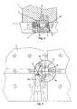
- FIGS. 1 and 4 show a sectional view of a clamping device for the releasable fastening of a workpiece or workpiece carrier 1 on a machine table 2 or another suitable support of a processing machine in the released or clamped state.
- the clamping device contains, as connecting elements, a connecting bolt 3 fastened to the workpiece or workpiece carrier 1 and a rotatable clamping receptacle 4 integrated in the machine table 2, which contains a clamping ring 5 which can be coupled to the connecting bolt 3 and a lower collar 6 which is integral with the latter and has an annular upper contact surface 7.
- a laterally projecting hinge eye 8 is formed for connection to a drive 9 shown in FIG. 3 and explained in more detail below for rotating the clamping receptacle 4.
- the clamping receptacle 4 is accommodated in a corresponding recess 10 in the machine table 2 and is rotated about its central axis 13 by a guide ring 12 fastened within a recess 11 in the machine table 2 and axially secured in the clamping direction.
- the guide ring 12 has on its underside an inwardly projecting ring shoulder 14, on the cylindrical inner wall of which the clamping ring 5 is guided radially.
- the clamping receptacle 4 rests with its annular contact surface 7 on the underside of the guide ring 12.
- the clamping receptacle 4 is prestressed in the direction of the guide ring 12 by a compression spring 15 clamped between the bottom of the recess 10 and the underside of the clamping receptacle 4.
- the contact surface 7 of the clamping receptacle 4 and the underside of the guide ring 12 can be coated for easier rotation.
- an axial bearing designed as a sliding or rolling bearing can also be provided.
- the guide ring 12 has a plurality of through bores 16 spaced apart from one another in the circumferential direction for suitable holding screws for attachment to the machine table 2.
- a sealing ring 17 is inserted above the annular shoulder 14 between the guide ring and the clamping ring 5.
- four lugs 19 are arranged on the inside of the clamping ring 5, each offset by 90 ° to one another and separated from one another by spaces 18.
- the inwardly projecting lugs 19 have wedge-shaped contact surfaces 20 which can be seen on their underside in FIG.
- These approaches 19 are produced in the embodiment shown in that in the clamping ring 5, the four spaces 18 first, for example by a end mill or the like. getting produced. Subsequently Then, on the inside of the inwardly projecting sections, four identical thread grooves 21, recognizable in FIG. 1, are produced with a predetermined pitch and a trapezoidal cross section to produce separate internal thread sections.
- the cylindrical connecting bolt 3 shown in a bottom view in FIG. 2 contains a lower, slimmer clamping region 22 which can be inserted into the clamping ring 5 and an upper, wider guide region 23, which is designed for a precise fit in an upper cylindrical receiving region 24 of the guide ring 10.
- the connecting bolt 3 has a central through bore 25 for a fastening screw for fastening it to the workpiece or workpiece carrier 1.
- the connecting bolt 3 is secured against rotation by means of a lateral pin 26.
- Four projections 27 with an upper wedge-shaped contact surface 28 are arranged on the lower clamping region 22 of the connecting bolt 3, each offset by 90 ° to one another and spaced apart in the circumferential direction.
- the projections 27 of the connecting bolt 3 are designed in the form of identical external thread sections, each with a thread beginning at the same height and the same pitch.
- the external thread sections which also end at the same height in each case, have a trapezoidal profile for engaging in the thread grooves 21 of the clamping ring 5.
- the drive 9 for rotating the clamping receptacle 4 is designed as a spindle-nut drive with a threaded spindle 30 running tangentially to the clamping receptacle 4 and guided within a threaded bushing 29.
- the threaded bushing 29 is secured in the axial direction within a bearing sleeve 31 inserted on the side wall of the machine table 2 and is rotatably guided by means of rotary bearings 32.
- the end of the threaded spindle 30 projecting inwards from the threaded bushing 29 is connected to the clamping receptacle 4 via an articulated lever 33.
- the articulated lever 33 is connected to the articulated eye 8 of the clamping receptacle 4 via a first articulated pin 34 and to the inwardly projecting end of the threaded spindle 30 via a second articulated pin 35.
- an inner square 36 is provided for the attachment of a clamping tool or the like.
- the connecting bolt 3 is in the release position shown in FIGS Clamping receptacle inserted such that the outwardly projecting projections 27 on the connecting bolt 3 are inserted into the spaces 18 of the clamping ring 5.
- the projections 27 are arranged below the lugs 19 and in the not yet rotated release position of the clamping receptacle 4 there is an axial play between the mutually associated contact surfaces 20 and 28. Only by subsequent rotation of the clamping receptacle 4 into a clamping position shown in FIGS.
- the invention is not limited to the embodiment described above and shown in the drawing.
- suitable drives can also be used to turn the clamping fixture.
- the connecting bolt can also be arranged on the machine table and the associated clamping receptacle in a suitable workpiece holder or the like.
Landscapes
- Engineering & Computer Science (AREA)
- Mechanical Engineering (AREA)
- Jigs For Machine Tools (AREA)
- Gripping On Spindles (AREA)
- Sampling And Sample Adjustment (AREA)
- Physical Vapour Deposition (AREA)
- Machine Tool Units (AREA)
Abstract
Description
Die Erfindung betrifft eine Spannvorrichtung zur lösbaren Befestigung eines Werkstücks oder Werkstückträgers an Bearbeitungsmaschinen nach dem Oberbegriff des Anspruchs 1.The invention relates to a clamping device for the detachable fastening of a workpiece or workpiece carrier to processing machines according to the preamble of
Eine derartige Spannvorrichtung ist aus der DE 199 34 835 A1 bekannt. Dort wird der an einer Palette befestigte Einzugsbolzen durch radial verschiebbare Kugeln innerhalb eines sogenannten Schnellspannzylinders fixiert. Die Kugeln greifen hierzu in einer Spannstellung in eine entsprechende Ringnut an der Außenseite des Einzugsbolzens ein. Die radiale Verschiebung der Kugeln zum Spannen und Lösen des Einzugsbolzens erfolgt über einen Hydraulikkolben, der durch eine Tellerfederanordnung in eine Spannstellung mit nach innen gedrückten Kugeln beaufschlagt wird. Zum Entriegeln des Einzugsbolzens innerhalb des Schnellspannzylinders muß der Druckkolben durch entsprechende Beaufschlagung mit Hydraulikfluid entgegen der Kraft der Tellerfederanordnung verschoben werden, wobei sich die Kugeln radial nach außen bewegen und außer Eingriff mit der Ringnut des Einzugsbolzens gelangen. Damit ist der Einzugsbolzen entgegen der Federkraft des Tellerfederpakets entriegelt. Bei einem derartigen Spannmechanismus treten jedoch aufgrund der kugelförmigen Spannelemente hohe Hertz'sche Pressungen an den Spannflächen auf, was zu entsprechend schnelleren Verschleißerscheinungen an den jeweiligen Bauteilen führen kann. Außerdem ist bei einer derartigen Spannvorrichtung eine gesonderte Hydraulikversorgung erforderlich.Such a tensioning device is known from DE 199 34 835 A1. There, the pull-in bolt attached to a pallet is fixed by radially displaceable balls inside a so-called quick-release cylinder. For this purpose, the balls engage in a corresponding annular groove on the outside of the draw-in bolt in a clamping position. The radial displacement of the balls for tensioning and loosening the pull-in pin takes place via a hydraulic piston which is acted upon by a plate spring arrangement in a clamping position with balls pressed inwards. To unlock the pull-in pin within the quick-release cylinder, the pressure piston must be moved against the force of the plate spring arrangement by correspondingly applying hydraulic fluid, the balls moving radially outward and disengaging from the annular groove of the pull-in pin. The pull-in bolt is thus unlocked against the spring force of the plate spring assembly. With such a clamping mechanism, however, high Hertzian pressures occur on the clamping surfaces due to the spherical clamping elements, which can lead to correspondingly faster signs of wear on the respective components. In addition, a separate hydraulic supply is required in such a clamping device.
Bei einer aus der DE 196 36 375 A1 bekannten weiteren Spannvorrichtung zur Befestigung von Paletten auf einer Bearbeitungsmaschine wird ein an der Unterseite einer Palette befestigter Einzugsbolzen innerhalb eines Gehäuses durch mehrere radial verschiebbare Verriegelungskolben fixiert, die in eine entsprechende Umfangsnut des Einzugsbolzens eingreifen. Die radialen Verriegelungskolben sind in einem inneren Ringkolben verschiebbar geführt und werden durch einen federbaufschlagten äußeren Ringkolben mit schrägen Druckflächen in die Umgangsnut des Einzugsbolzens gedrückt. Zum Lösen der Verriegelung werden die beiden Ringkolben mit Drucköl beaufschlagt und entgegen der Federkraft nach oben bewegt. Dabei werden die Verriegelungskolben radial nach außen verschoben und geben den Einzugsbolzen frei. Diese bekannte Spannvorrichtung weist eine konstruktiv aufwendige Kolben-Zylinder-Anordnung auf, die einen relativ großen Bauraum erfordert. Auch hier ist für die Betätigung der Spannvorrichtung eine gesonderte Druckversorgung erforderlich.In a further clamping device known from DE 196 36 375 A1 for fastening pallets on a processing machine, a pull-in bolt fastened to the underside of a pallet is fixed within a housing by a plurality of radially displaceable locking pistons which engage in a corresponding circumferential groove of the pull-in bolt. The radial locking pistons are slidably guided in an inner annular piston and are pressed into the surrounding groove of the pull-in pin by a spring-loaded outer annular piston with oblique pressure surfaces. To release the lock, the two ring pistons are pressurized with oil and moved upwards against the spring force. The locking pistons are moved radially outwards and release the pull-in bolt. This known clamping device has a structurally complex Piston-cylinder arrangement, which requires a relatively large amount of space. Here too, a separate pressure supply is required to actuate the tensioning device.
Aus der DE 199 41 424 C2 ist ferner eine Aufspannvorrichtung zum Aufspannen eines Werkstücks zwischen einer festen Wand und einem Werkstücktisch bekannt. Bei dieser Vorrichtung wird jedoch durch Verdrehung eines Druckkolbens keine Einzugskraft zum Einziehen eines Verbindungselements, sondern eine Druckkraft zum Ausfahren des Druckkolbens für die Anpressung des Werkstücks auf die Unterlage erzeugt. Außerdem erfolgt bei dieser bekannten Aufspannvorrichtung ein Zusammenstecken der Verbindungselemente nur bei der Montage und nicht bei jedem Spannvorgang, wie dies bei der erfindungsgemäßen Spannvorrichtung der Fall ist.A clamping device for clamping a workpiece between a fixed wall and a workpiece table is also known from DE 199 41 424 C2. In this device, however, rotation of a pressure piston does not generate a pull-in force for pulling in a connecting element, but rather a pressure force for extending the pressure piston for pressing the workpiece onto the base. In addition, in this known clamping device, the connecting elements are plugged together only during assembly and not during each clamping process, as is the case with the clamping device according to the invention.
Aufgabe der Erfindung ist es, eine Spannvorrichtung der eingangs genannten Art zu schaffen, die bei einfachem technischen Aufbau und bei geringem Bauraum eine sichere und positionsgenaue, bei Bedarf auch schnell wieder lösbare Befestigung von Werkstücken oder Werkstückträgern an Bearbeitungsmaschinen ermöglicht.The object of the invention is to provide a clamping device of the type mentioned which, with a simple technical structure and with a small installation space, enables secure and positionally accurate, if required also quickly detachable fastening of workpieces or workpiece carriers to processing machines.
Diese Aufgabe wird durch einen Spannvorrichtung mit den Merkmalen des Anspruchs 1 gelöst. Zweckmäßige Ausgestaltungen und vorteilhafte Weiterbildungen der Erfindung sind in den Unteransprüchen angegeben.This object is achieved by a tensioning device with the features of
Die erfindungsgemäße Spannvorrichtung zeichnet sich durch eine äußerst kompakte Bauweise mit einem vergleichsweise kleinen Außendurchmesser und einer geringen Bauhöhe aus. Die Spannvorrichtung kann so besonders gut auch an Bearbeitungsmaschinen mit beschränktem Platzangebot eingesetzt werden. Übliche und gängige Schnittstellen können somit weitgehend beibehalten werden. Durch die relativ zueinander verdrehbaren Ansätze und Vorsprünge mit den in Eingriff bringbaren Keilflächen wird außerdem durch eine Art Drehkeilverbindung mit relativ einfachen konstruktiven Mitteln eine sichere und paßgenaue Fixierung auch schwerer Werkstücke ermöglicht. Zur Betätigung der Spannvorrichtung ist nur ein einfacher Drehantrieb erforderlich, der auf konstruktiv einfache und platzsparende Weise realisiert werden kann. Die nur wenigen Teile der Spannvorrichtung können außerdem relativ leicht gegen Verschmutzung oder eindringendes Kühlmittel geschützt werden, wodurch die Zuverlässigkeit und Lebensdauer der Spannvorrichtung verbessert wird.The tensioning device according to the invention is characterized by an extremely compact design with a comparatively small outer diameter and a low overall height. The clamping device can thus also be used particularly well on processing machines with limited space. Usual and common interfaces can thus largely be retained. Due to the lugs and projections which can be rotated relative to one another and the wedge surfaces which can be brought into engagement, a secure and precisely fitting fixing of even heavy workpieces is also made possible by a type of wedge connection with relatively simple constructional means. To operate the clamping device, only a simple rotary drive is required, which can be implemented in a structurally simple and space-saving manner. The few parts of the tensioning device can also be protected relatively easily against dirt or penetrating coolant, which improves the reliability and service life of the tensioning device.
In einer besonders zweckmäßigen Ausführung der Erfindung sind vier in Umfangsrichtung voneinander beabstandete verdrehbare Ansätze an dem einen Verbindungselement und vier dazu korrespondierende verdrehfeste Vorsprünge an dem anderen Verbindungselement mit zueinander korrespondierenden und durch gegenseitige Verdrehung miteinander in Kontakt gelangenden Keilflächen vorgesehen. In entsprechender Weise können aber auch nur zwei, drei oder mehr als vier Ansätze bzw. Vorsprünge vorhanden sein. Die Ansätze sind zweckmäßigerweise an einem innerhalb eines Maschinentischs oder einer anderen geeigneten Auflage der Bearbeitungsmaschine verdrehbar angeordneten Spannring einer Spannaufnahme und die dazugehörigen Vorsprünge an einem in den Spannring einführbaren Verbindungsbolzen angeordnet. Die Verdrehung des Spannaufnahme kann auf besonders einfache und platzsparende Weise durch einen in den Maschinentisch integrierten Spindel-Mutter-Antrieb über einen Gelenkhebel erfolgen. Selbstverständlich sind auch andere Drehantriebe möglich.In a particularly expedient embodiment of the invention, four rotatable lugs spaced apart from one another in the circumferential direction are provided on the one connecting element and four corresponding non-rotatable projections on the other connecting element with wedge surfaces which correspond to one another and come into contact with one another by mutual rotation. In a corresponding manner, however, there can also be only two, three or more than four lugs or projections. The approaches are expediently arranged on a clamping ring of a clamping receptacle which is rotatably arranged within a machine table or another suitable support of the processing machine, and the associated projections are arranged on a connecting bolt which can be inserted into the clamping ring. The clamping fixture can be rotated in a particularly simple and space-saving manner by means of a spindle-nut drive integrated in the machine table via an articulated lever. Of course, other rotary actuators are also possible.
Weitere Besonderheiten und Vorzüge der Erfindung ergeben sich aus der folgenden Beschreibung eines Ausführungsbeispiels anhand der Zeichnung. Es zeigen:
-
Figur 1 - eine Schnittansicht einer Spannvorrichtung zur lösbaren Befestigung eines Werkstücks oder Werkstückträgers an einer Bearbeitungsmaschine im gelösten Zustand;
-
Figur 2 - einen Verbindungsbolzen der in
Figur 1 gezeigten Spannvorrichtung in einer Unteransicht; -
Figur 3 - eine zum Teil geschnittene Draufsicht auf eine Spannaufnahme der in
Figur 1 gezeigten Spannvorrichtung in einer Lösestellung; -
Figur 4 - eine Schnittansicht der in
Figur 1 gezeigten Spannvorrichtung im gespannten Zustand und -
Figur 5 - eine zum Teil geschnittene Draufsicht auf eine Spannaufnahme der in
Figur 1 gezeigten Spannvorrichtung in einer Spannstellung.
- Figure 1
- a sectional view of a clamping device for releasably fastening a workpiece or workpiece carrier to a processing machine in the released state;
- Figure 2
- a connecting pin of the clamping device shown in Figure 1 in a bottom view;
- Figure 3
- a partially sectioned plan view of a clamping receptacle of the clamping device shown in Figure 1 in a release position;
- Figure 4
- a sectional view of the tensioning device shown in Figure 1 in the tensioned state and
- Figure 5
- a partially sectioned plan view of a clamping receptacle of the clamping device shown in Figure 1 in a clamping position.
In den Figuren 1 und 4 ist eine Schnittansicht einer Spannvorrichtung zur lösbaren Befestigung eines Werkstücks bzw. Werkstückträgers 1 auf einem Maschinentisch 2 oder einer anderen geeigneten Auflage einer Bearbeitungsmaschine im gelösten bzw. gespannten Zustand gezeigt. Die Spannvorrichtung enthält als Verbindungselemente einen am Werkstück bzw. Werkstückträger 1 befestigten Verbindungsbolzen 3 und eine im Maschinentisch 2 integrierte verdrehbare Spannaufnahme 4, die einem mit dem Verbindungsbolzen 3 koppelbaren Spannring 5 und einem mit diesem einstückigen unteren Bund 6 mit einer ringförmigen oberen Anlagefläche 7 enthält. An dem Bund 6 ist ein seitlich vorstehendes Gelenkauge 8 für die Verbindung mit einer in Figur 3 dargestellten und im folgenden noch näher erläuterten Antrieb 9 zur Drehung der Spannaufnahme 4 angeformt.FIGS. 1 and 4 show a sectional view of a clamping device for the releasable fastening of a workpiece or
Die Spannaufnahme 4 ist gemäß Figur 1 in einer entsprechenden Ausnehmung 10 des Maschinentisches 2 untergebracht und wird durch einen innerhalb einer Vertiefung 11 des Maschinentisches 2 befestigten Führungsring 12 um ihre Mittelachse 13 verdrehbar und in Spannrichtung axial gesichert geführt. Hierzu weist der Führungsring 12 an seiner Unterseite eine nach innen vorstehende Ringschulter 14 auf, an deren zylindrischen Innenwand der Spannring 5 radial geführt wird. Zur Sicherung in der axialen Spannrichtung liegt die Spannaufnahme 4 mit ihrer ringförmigen Anlagefläche 7 an der Unterseite des Führungsrings 12 an. Durch eine zwischen dem Boden der Ausnehmung 10 und der Unterseite der Spannaufnahme 4 eingespannte Druckfeder 15 wird die Spannaufnahme 4 in Richtung des Führungsrings 12 vorgespannt. Die Anlagefläche 7 der Spannaufnahme 4 und die Unterseite des Führungsrings 12 können zur leichteren Drehung beschichtet sein. Zwischen der Anlagefläche 7 und der Unterseite des Führungsrings 12 kann aber auch ein als Gleit- oder Wälzlager ausgeführtes Axiallager vorgesehen sein. Der Führungsring 12 weist zur Befestigung am Maschinentisch 2 mehrere in Umfangsrichtung voneinander beabstandete Durchgangsbohrungen 16 für geeignete Halteschrauben auf. Oberhalb der Ringschulter 14 ist zwischen dem Führungsring und dem Spannring 5 ein Dichtring 17 eingesetzt.1, the
Wie besonders aus Figur 3 hervorgeht, sind an der Innenseite des Spannrings 5 vier um jeweils 90° zueinander winkelversetzte und durch Zwischenräume 18 voneinander getrennte Ansätze 19 angeordnet. Die nach innen vorstehenden Ansätze 19 weisen an ihrer Unterseite in Figur 1 erkennbare keilförmige Anlageflächen 20 auf. Diese Ansätze 19 sind bei der gezeigten Ausführung dadurch hergestellt, daß in dem Spannring 5 zunächst die vier Zwischenräume 18 z.B. durch einen Fingerfräser o.ä. hergestellt werden. Anschließend werden dann an der Innenseite der nach innen vorstehenden Abschnitte vier in Figur 1 erkennbare identische Gewindenuten 21 mit einer vorgegebenen Steigung und einem trapezförmigen Querschnitt zur Erzeugung voneinander getrennter Innengewindeabschnitte gefertigt.As can be seen particularly from FIG. 3, four
Der in Figur 2 in einer Unteransicht gezeigte zylindrische Verbindungsbolzen 3 enthält einen in den Spannring 5 einführbaren unteren schlankeren Spannbereich 22 und einen oberen breiteren Führungsbereich 23, der zum paßgenauen Einsatz in einen oberen zylindrischen Aufnahmebereich 24 des Führungsrings 10 ausgebildet ist. Der Verbindungsbolzen 3 weist zu seiner Befestigung an dem Werkstück bzw. Werkstückträger 1 eine zentrale Durchgangsbohrung 25 für eine Befestigungsschraube auf. Über einen seitlichen Stift 26 wird eine Verdrehsicherung des Verbindungsbolzens 3 erreicht. An dem unteren Spannbereich 22 des Verbindungsbolzens 3 sind vier um jeweils 90° zueinander winkelversetzte und in Umfangsrichtung voneinander beabstandete Vorsprünge 27 mit einer oberen keilförmigen Anlagefläche 28 angeordnet. Bei der gezeigten Ausführung sind die Vorsprünge 27 des Verbindungsbolzens 3 in Form von identisch ausgeführten Außengewindeabschnitten mit einem jeweils auf derselben Höhe liegenden Gewindeanfang und derselben Steigung ausgeführt. Die auch auf jeweils derselben Höhe endenden Außengewindeabschnitte weisen ein trapezförmiges Profil zum Eingriff in die Gewindenuten 21 des Spannrings 5 auf.The cylindrical connecting
Der Antrieb 9 zur Drehung der Spannaufnahme 4 ist bei der in Figur 3 gezeigten Ausführung als Spindel-Mutter-Antrieb mit einer tangential zur Spannaufnahme 4 verlaufenden und innerhalb einer Gewindebuchse 29 geführten Gewindespindel 30 ausgeführt. Die Gewindebuchse 29 ist innerhalb einer an der Seitenwand des Maschinentischs 2 eingesetzten Lagerhülse 31 in der Axialrichtung gesichert und über Drehlager 32 verdrehbar geführt. Das von der Gewindebuchse 29 nach innen vorstehende Ende der Gewindespindel 30 ist über einen Gelenkhebel 33 mit der Spannaufnahme 4 verbunden. Hierzu ist der Gelenkhebel 33 ist über einen ersten Gelenkbolzen 34 mit dem Gelenkauge 8 der Spannaufnahme 4 und über einen zweiten Gelenkbolzen 35 mit dem nach innen vorstehenden Ende der Gewindespindel 30 verbunden. An dem nach außen vorstehenden äußeren Ende der Gewindebuchse 29 ist ein Innenvierkant 36 zum Ansatz eines Spannwerkzeugs oder dgl. vorgesehen.In the embodiment shown in FIG. 3, the
Zur Befestigung des Werkstücks oder Werkstückträgers 1 an dem Maschinentisch 2 wird der Verbindungsbolzen 3 bei der in den Figuren 1 und 3 gezeigten Lösestellung der Spannaufnahme derart eingesteckt, daß die nach außen vorstehenden Vorsprünge 27 am Verbindungsbolzen 3 in die Zwischenräume 18 des Spannrings 5 eingeführt werden. Wenn der Werkstückträger 1 mit seiner Unterseite zur Auflage auf der Oberseite des Maschinentischs 2 gelangt, sind die Vorsprünge 27 unterhalb der Ansätze 19 angeordnet und in der noch nicht verdrehten Lösestellung des Spannaufnahme 4 ist ein axiales Spiel zwischen den einander zugeordneten Anlageflächen 20 und 28 vorhanden. Erst durch anschließende Drehung des Spannaufnahme 4 in eine gemäß Figur 4 und 5 gezeigte Spannstellung gelangen die zunächst axial beabstandeten keilförmigen Anlageflächen 20 und 28 miteinander in Kontakt, so daß sich die Vorsprünge 27 mit ihren keilförmigen Anlageflächen 28 unter den Ansätzen 19 des Spannrings 5 verkeilen. Dabei wird eine axiale Einzugskraft erzeugt und der Werkstückträger 1 auf die Oberfläche des Maschinentischs 1 gepreßt. Durch eine Drehung der Spannaufnahme 4 in entgegengesetzter Richtung kann die Keilverbindung auf einfache Weise wieder gelöst werden.To fasten the workpiece or
Die Erfindung ist nicht auf das vorstehend beschriebene und in der Zeichnung dargestellte Ausführungsbeispiel beschränkt. So können z.B. anstelle des Spindel-Mutter-Antriebs auch andere geeignete Antriebe zur Verdrehung des Spannaufnahme zum Einsatz gelangen. Bei entsprechenden baulichen Gegebenheiten kann außerdem der Verbindungsbolzen auch am Maschinentisch und die dazugehörige Spannaufnahme in einem geeigneten Werkstückträger oder dgl. angeordnet sein.The invention is not limited to the embodiment described above and shown in the drawing. For example, Instead of the spindle-nut drive, other suitable drives can also be used to turn the clamping fixture. In the case of corresponding structural conditions, the connecting bolt can also be arranged on the machine table and the associated clamping receptacle in a suitable workpiece holder or the like.
Claims (12)
Applications Claiming Priority (2)
| Application Number | Priority Date | Filing Date | Title |
|---|---|---|---|
| DE10245377A DE10245377A1 (en) | 2002-09-28 | 2002-09-28 | jig |
| DE10245377 | 2002-09-28 |
Publications (2)
| Publication Number | Publication Date |
|---|---|
| EP1402995A1 true EP1402995A1 (en) | 2004-03-31 |
| EP1402995B1 EP1402995B1 (en) | 2005-08-31 |
Family
ID=31969697
Family Applications (1)
| Application Number | Title | Priority Date | Filing Date |
|---|---|---|---|
| EP03016099A Expired - Lifetime EP1402995B1 (en) | 2002-09-28 | 2003-07-16 | Clamping device |
Country Status (3)
| Country | Link |
|---|---|
| EP (1) | EP1402995B1 (en) |
| AT (1) | ATE303227T1 (en) |
| DE (2) | DE10245377A1 (en) |
Cited By (5)
| Publication number | Priority date | Publication date | Assignee | Title |
|---|---|---|---|---|
| WO2015036219A1 (en) * | 2013-09-10 | 2015-03-19 | Andreas Maier Gmbh & Co. Kg | Clamping device for clamping at least one clamping nipple |
| EP2905106A1 (en) * | 2014-02-05 | 2015-08-12 | Liebherr-Werk Biberach GmbH | Neutral point positioning and tensioning system |
| CN111515714A (en) * | 2019-02-05 | 2020-08-11 | 株式会社莱茵瓦库斯 | Workpiece holding tool |
| JP2024098296A (en) * | 2023-01-10 | 2024-07-23 | 株式会社ラインワークス | Work holder |
| CN119077514A (en) * | 2024-11-07 | 2024-12-06 | 赣州艺佳兴陶瓷有限公司 | A ceramic edge grinding device for ceramic production |
Families Citing this family (4)
| Publication number | Priority date | Publication date | Assignee | Title |
|---|---|---|---|---|
| DE102005043751A1 (en) * | 2005-09-13 | 2007-03-22 | Werkstückspanntechnik GmbH | Clamping device for palettes, discs, toolpieces or tools to a machine table consisting of tenter hook with slit hinged radially to axis of catchment pieces positioned precisely on table |
| DE202008004787U1 (en) | 2008-04-04 | 2008-07-03 | Werkstückspanntechnik GmbH | Clamping drive for a low-tension clamping device |
| DE102023003507A1 (en) | 2023-08-25 | 2025-02-27 | Martin Kratochwille | clamping module for a machine tool and clamping system |
| CN120941059B (en) * | 2025-10-15 | 2026-01-27 | 山西机电职业技术学院 | A machine tool boring mechanism |
Citations (6)
| Publication number | Priority date | Publication date | Assignee | Title |
|---|---|---|---|---|
| DE3309555A1 (en) * | 1983-03-17 | 1984-09-20 | Grüner, Horst, Dipl.-Ing. (FH), 7347 Bad Überkingen | Arrangement for clamping or unloading workpieces, to be used in combination with a machine tool |
| US5634757A (en) * | 1994-08-10 | 1997-06-03 | Schanz; Manfred | Fastening device for a tool or workpiece |
| US5636425A (en) * | 1994-01-26 | 1997-06-10 | Best; Norman D. | Method for processing and assembly of small parts utilizing a robot |
| DE19636375A1 (en) * | 1996-09-09 | 1998-03-12 | Emil Stark | Quick release for a pallet under chip flight |
| DE19934835A1 (en) * | 1998-07-29 | 2000-02-03 | Emil Stark | Quick clamping cylinder for clamping workpieces on carrier plates for machining |
| DE19941424A1 (en) * | 1999-08-30 | 2001-04-19 | Bodo Bahr | Device to clamp work piece to table of machine tool has piston with support webs engaging on inclined wedge surfaces inside housing |
-
2002
- 2002-09-28 DE DE10245377A patent/DE10245377A1/en not_active Withdrawn
-
2003
- 2003-07-16 AT AT03016099T patent/ATE303227T1/en not_active IP Right Cessation
- 2003-07-16 EP EP03016099A patent/EP1402995B1/en not_active Expired - Lifetime
- 2003-07-16 DE DE50301076T patent/DE50301076D1/en not_active Expired - Fee Related
Patent Citations (6)
| Publication number | Priority date | Publication date | Assignee | Title |
|---|---|---|---|---|
| DE3309555A1 (en) * | 1983-03-17 | 1984-09-20 | Grüner, Horst, Dipl.-Ing. (FH), 7347 Bad Überkingen | Arrangement for clamping or unloading workpieces, to be used in combination with a machine tool |
| US5636425A (en) * | 1994-01-26 | 1997-06-10 | Best; Norman D. | Method for processing and assembly of small parts utilizing a robot |
| US5634757A (en) * | 1994-08-10 | 1997-06-03 | Schanz; Manfred | Fastening device for a tool or workpiece |
| DE19636375A1 (en) * | 1996-09-09 | 1998-03-12 | Emil Stark | Quick release for a pallet under chip flight |
| DE19934835A1 (en) * | 1998-07-29 | 2000-02-03 | Emil Stark | Quick clamping cylinder for clamping workpieces on carrier plates for machining |
| DE19941424A1 (en) * | 1999-08-30 | 2001-04-19 | Bodo Bahr | Device to clamp work piece to table of machine tool has piston with support webs engaging on inclined wedge surfaces inside housing |
Cited By (5)
| Publication number | Priority date | Publication date | Assignee | Title |
|---|---|---|---|---|
| WO2015036219A1 (en) * | 2013-09-10 | 2015-03-19 | Andreas Maier Gmbh & Co. Kg | Clamping device for clamping at least one clamping nipple |
| EP2905106A1 (en) * | 2014-02-05 | 2015-08-12 | Liebherr-Werk Biberach GmbH | Neutral point positioning and tensioning system |
| CN111515714A (en) * | 2019-02-05 | 2020-08-11 | 株式会社莱茵瓦库斯 | Workpiece holding tool |
| JP2024098296A (en) * | 2023-01-10 | 2024-07-23 | 株式会社ラインワークス | Work holder |
| CN119077514A (en) * | 2024-11-07 | 2024-12-06 | 赣州艺佳兴陶瓷有限公司 | A ceramic edge grinding device for ceramic production |
Also Published As
| Publication number | Publication date |
|---|---|
| ATE303227T1 (en) | 2005-09-15 |
| EP1402995B1 (en) | 2005-08-31 |
| DE50301076D1 (en) | 2005-10-06 |
| DE10245377A1 (en) | 2004-04-15 |
Similar Documents
| Publication | Publication Date | Title |
|---|---|---|
| EP0354363A2 (en) | Clamping device with a screwed bush | |
| EP0339321A1 (en) | Clamping device for the axial clamping of two machine parts seperable from each other | |
| EP4003649A1 (en) | Bore clamp | |
| DE10041844C2 (en) | Mechanically operated chuck | |
| EP1920152B1 (en) | Two-piece piston for an internal combustion engine | |
| EP1453630B1 (en) | Clamping device | |
| DE3835879C1 (en) | ||
| EP1738864A2 (en) | Clamping device | |
| EP1402995B1 (en) | Clamping device | |
| EP1663555B1 (en) | Clamping device | |
| DE69215905T2 (en) | TENSIONER FOR MILLING OR SIMILAR, ADAPTABLE FOR DIFFERENT HOLDER SIZES | |
| DE102019115387A1 (en) | Clamping device for clamping an object, in particular a tool | |
| DE3839681C2 (en) | ||
| DE102017000671B4 (en) | Lathe chuck and machine tool | |
| EP0417613A1 (en) | Device for coupling two parts of machine tools | |
| EP1213065B1 (en) | Punchtool with adjusting ring | |
| DE19920264B4 (en) | Tool holder for a high-frequency spindle | |
| DE69427043T2 (en) | AXLE JOINT | |
| DE9305188U1 (en) | Quick release device for jigsaw blades | |
| DE102010010209B4 (en) | die table | |
| DE102018100355B4 (en) | Coupling device for connecting a lifting device to a load | |
| EP4000810A1 (en) | Device for releasing an inner bearing from a crank bearing | |
| EP4202393B1 (en) | Clamping device for clamping a component on a machine element of a machine tool | |
| DE3700841A1 (en) | CLUTCH ELEMENT, IN PARTICULAR FOR FORCE AND FORM-CONNECTIVE CONNECTION OF A TOOL HEAD TO A TOOL HOLDER | |
| DE20003729U1 (en) | Clamping device for fixing a feed pin |
Legal Events
| Date | Code | Title | Description |
|---|---|---|---|
| PUAI | Public reference made under article 153(3) epc to a published international application that has entered the european phase |
Free format text: ORIGINAL CODE: 0009012 |
|
| AK | Designated contracting states |
Kind code of ref document: A1 Designated state(s): AT BE BG CH CY CZ DE DK EE ES FI FR GB GR HU IE IT LI LU MC NL PT RO SE SI SK TR |
|
| AX | Request for extension of the european patent |
Extension state: AL LT LV MK |
|
| 17P | Request for examination filed |
Effective date: 20040930 |
|
| 17Q | First examination report despatched |
Effective date: 20041029 |
|
| AKX | Designation fees paid |
Designated state(s): AT BE BG CH CY CZ DE DK EE ES FI FR GB GR HU IE IT LI LU MC NL PT RO SE SI SK TR |
|
| GRAP | Despatch of communication of intention to grant a patent |
Free format text: ORIGINAL CODE: EPIDOSNIGR1 |
|
| GRAS | Grant fee paid |
Free format text: ORIGINAL CODE: EPIDOSNIGR3 |
|
| GRAA | (expected) grant |
Free format text: ORIGINAL CODE: 0009210 |
|
| AK | Designated contracting states |
Kind code of ref document: B1 Designated state(s): AT BE BG CH CY CZ DE DK EE ES FI FR GB GR HU IE IT LI LU MC NL PT RO SE SI SK TR |
|
| PG25 | Lapsed in a contracting state [announced via postgrant information from national office to epo] |
Ref country code: RO Free format text: LAPSE BECAUSE OF FAILURE TO SUBMIT A TRANSLATION OF THE DESCRIPTION OR TO PAY THE FEE WITHIN THE PRESCRIBED TIME-LIMIT Effective date: 20050831 Ref country code: FI Free format text: LAPSE BECAUSE OF FAILURE TO SUBMIT A TRANSLATION OF THE DESCRIPTION OR TO PAY THE FEE WITHIN THE PRESCRIBED TIME-LIMIT Effective date: 20050831 Ref country code: CZ Free format text: LAPSE BECAUSE OF FAILURE TO SUBMIT A TRANSLATION OF THE DESCRIPTION OR TO PAY THE FEE WITHIN THE PRESCRIBED TIME-LIMIT Effective date: 20050831 Ref country code: SI Free format text: LAPSE BECAUSE OF FAILURE TO SUBMIT A TRANSLATION OF THE DESCRIPTION OR TO PAY THE FEE WITHIN THE PRESCRIBED TIME-LIMIT Effective date: 20050831 Ref country code: SK Free format text: LAPSE BECAUSE OF FAILURE TO SUBMIT A TRANSLATION OF THE DESCRIPTION OR TO PAY THE FEE WITHIN THE PRESCRIBED TIME-LIMIT Effective date: 20050831 Ref country code: IE Free format text: LAPSE BECAUSE OF FAILURE TO SUBMIT A TRANSLATION OF THE DESCRIPTION OR TO PAY THE FEE WITHIN THE PRESCRIBED TIME-LIMIT Effective date: 20050831 |
|
| REG | Reference to a national code |
Ref country code: CH Ref legal event code: EP Ref country code: CH Ref legal event code: NV Representative=s name: LUCHS & PARTNER PATENTANWAELTE Ref country code: GB Ref legal event code: FG4D Free format text: NOT ENGLISH |
|
| GBT | Gb: translation of ep patent filed (gb section 77(6)(a)/1977) |
Effective date: 20050831 |
|
| REG | Reference to a national code |
Ref country code: IE Ref legal event code: FG4D Free format text: LANGUAGE OF EP DOCUMENT: GERMAN |
|
| REF | Corresponds to: |
Ref document number: 50301076 Country of ref document: DE Date of ref document: 20051006 Kind code of ref document: P |
|
| PG25 | Lapsed in a contracting state [announced via postgrant information from national office to epo] |
Ref country code: GR Free format text: LAPSE BECAUSE OF FAILURE TO SUBMIT A TRANSLATION OF THE DESCRIPTION OR TO PAY THE FEE WITHIN THE PRESCRIBED TIME-LIMIT Effective date: 20051130 Ref country code: BG Free format text: LAPSE BECAUSE OF FAILURE TO SUBMIT A TRANSLATION OF THE DESCRIPTION OR TO PAY THE FEE WITHIN THE PRESCRIBED TIME-LIMIT Effective date: 20051130 Ref country code: SE Free format text: LAPSE BECAUSE OF FAILURE TO SUBMIT A TRANSLATION OF THE DESCRIPTION OR TO PAY THE FEE WITHIN THE PRESCRIBED TIME-LIMIT Effective date: 20051130 Ref country code: DK Free format text: LAPSE BECAUSE OF FAILURE TO SUBMIT A TRANSLATION OF THE DESCRIPTION OR TO PAY THE FEE WITHIN THE PRESCRIBED TIME-LIMIT Effective date: 20051130 |
|
| PG25 | Lapsed in a contracting state [announced via postgrant information from national office to epo] |
Ref country code: ES Free format text: LAPSE BECAUSE OF FAILURE TO SUBMIT A TRANSLATION OF THE DESCRIPTION OR TO PAY THE FEE WITHIN THE PRESCRIBED TIME-LIMIT Effective date: 20051212 |
|
| PG25 | Lapsed in a contracting state [announced via postgrant information from national office to epo] |
Ref country code: PT Free format text: LAPSE BECAUSE OF FAILURE TO SUBMIT A TRANSLATION OF THE DESCRIPTION OR TO PAY THE FEE WITHIN THE PRESCRIBED TIME-LIMIT Effective date: 20060222 |
|
| PG25 | Lapsed in a contracting state [announced via postgrant information from national office to epo] |
Ref country code: HU Free format text: LAPSE BECAUSE OF FAILURE TO SUBMIT A TRANSLATION OF THE DESCRIPTION OR TO PAY THE FEE WITHIN THE PRESCRIBED TIME-LIMIT Effective date: 20060301 |
|
| REG | Reference to a national code |
Ref country code: IE Ref legal event code: FD4D |
|
| ET | Fr: translation filed | ||
| PLBE | No opposition filed within time limit |
Free format text: ORIGINAL CODE: 0009261 |
|
| STAA | Information on the status of an ep patent application or granted ep patent |
Free format text: STATUS: NO OPPOSITION FILED WITHIN TIME LIMIT |
|
| PG25 | Lapsed in a contracting state [announced via postgrant information from national office to epo] |
Ref country code: MC Free format text: LAPSE BECAUSE OF NON-PAYMENT OF DUE FEES Effective date: 20060731 |
|
| 26N | No opposition filed |
Effective date: 20060601 |
|
| PGFP | Annual fee paid to national office [announced via postgrant information from national office to epo] |
Ref country code: FR Payment date: 20060914 Year of fee payment: 4 |
|
| REG | Reference to a national code |
Ref country code: FR Ref legal event code: ST Effective date: 20070330 |
|
| PGFP | Annual fee paid to national office [announced via postgrant information from national office to epo] |
Ref country code: DE Payment date: 20070706 Year of fee payment: 5 |
|
| PGFP | Annual fee paid to national office [announced via postgrant information from national office to epo] |
Ref country code: AT Payment date: 20070710 Year of fee payment: 5 Ref country code: CH Payment date: 20070712 Year of fee payment: 5 |
|
| PGFP | Annual fee paid to national office [announced via postgrant information from national office to epo] |
Ref country code: GB Payment date: 20070712 Year of fee payment: 5 |
|
| PGFP | Annual fee paid to national office [announced via postgrant information from national office to epo] |
Ref country code: BE Payment date: 20070711 Year of fee payment: 5 Ref country code: IT Payment date: 20070927 Year of fee payment: 5 Ref country code: NL Payment date: 20070710 Year of fee payment: 5 |
|
| PG25 | Lapsed in a contracting state [announced via postgrant information from national office to epo] |
Ref country code: FR Free format text: LAPSE BECAUSE OF NON-PAYMENT OF DUE FEES Effective date: 20060731 |
|
| PG25 | Lapsed in a contracting state [announced via postgrant information from national office to epo] |
Ref country code: EE Free format text: LAPSE BECAUSE OF FAILURE TO SUBMIT A TRANSLATION OF THE DESCRIPTION OR TO PAY THE FEE WITHIN THE PRESCRIBED TIME-LIMIT Effective date: 20050831 |
|
| PG25 | Lapsed in a contracting state [announced via postgrant information from national office to epo] |
Ref country code: LU Free format text: LAPSE BECAUSE OF NON-PAYMENT OF DUE FEES Effective date: 20060716 Ref country code: TR Free format text: LAPSE BECAUSE OF FAILURE TO SUBMIT A TRANSLATION OF THE DESCRIPTION OR TO PAY THE FEE WITHIN THE PRESCRIBED TIME-LIMIT Effective date: 20050831 |
|
| PG25 | Lapsed in a contracting state [announced via postgrant information from national office to epo] |
Ref country code: CY Free format text: LAPSE BECAUSE OF FAILURE TO SUBMIT A TRANSLATION OF THE DESCRIPTION OR TO PAY THE FEE WITHIN THE PRESCRIBED TIME-LIMIT Effective date: 20050831 |
|
| REG | Reference to a national code |
Ref country code: CH Ref legal event code: PL |
|
| GBPC | Gb: european patent ceased through non-payment of renewal fee |
Effective date: 20080716 |
|
| NLV4 | Nl: lapsed or anulled due to non-payment of the annual fee |
Effective date: 20090201 |
|
| PG25 | Lapsed in a contracting state [announced via postgrant information from national office to epo] |
Ref country code: DE Free format text: LAPSE BECAUSE OF NON-PAYMENT OF DUE FEES Effective date: 20090203 Ref country code: AT Free format text: LAPSE BECAUSE OF NON-PAYMENT OF DUE FEES Effective date: 20080716 |
|
| PG25 | Lapsed in a contracting state [announced via postgrant information from national office to epo] |
Ref country code: NL Free format text: LAPSE BECAUSE OF NON-PAYMENT OF DUE FEES Effective date: 20090201 |
|
| PG25 | Lapsed in a contracting state [announced via postgrant information from national office to epo] |
Ref country code: CH Free format text: LAPSE BECAUSE OF NON-PAYMENT OF DUE FEES Effective date: 20080731 Ref country code: GB Free format text: LAPSE BECAUSE OF NON-PAYMENT OF DUE FEES Effective date: 20080716 Ref country code: LI Free format text: LAPSE BECAUSE OF NON-PAYMENT OF DUE FEES Effective date: 20080731 |
|
| PG25 | Lapsed in a contracting state [announced via postgrant information from national office to epo] |
Ref country code: IT Free format text: LAPSE BECAUSE OF NON-PAYMENT OF DUE FEES Effective date: 20080716 |
|
| PG25 | Lapsed in a contracting state [announced via postgrant information from national office to epo] |
Ref country code: BE Free format text: LAPSE BECAUSE OF NON-PAYMENT OF DUE FEES Effective date: 20080731 |