EP1403060B1 - Démarrage à rampe de pression rapide - Google Patents
Démarrage à rampe de pression rapide Download PDFInfo
- Publication number
- EP1403060B1 EP1403060B1 EP03255926A EP03255926A EP1403060B1 EP 1403060 B1 EP1403060 B1 EP 1403060B1 EP 03255926 A EP03255926 A EP 03255926A EP 03255926 A EP03255926 A EP 03255926A EP 1403060 B1 EP1403060 B1 EP 1403060B1
- Authority
- EP
- European Patent Office
- Prior art keywords
- ink
- pressure
- catcher
- charge voltage
- startup
- Prior art date
- Legal status (The legal status is an assumption and is not a legal conclusion. Google has not performed a legal analysis and makes no representation as to the accuracy of the status listed.)
- Expired - Lifetime
Links
- 210000000744 eyelid Anatomy 0.000 claims description 32
- 239000012530 fluid Substances 0.000 claims description 19
- 238000000034 method Methods 0.000 claims description 15
- 238000007641 inkjet printing Methods 0.000 claims description 3
- 230000000977 initiatory effect Effects 0.000 claims 1
- 230000007704 transition Effects 0.000 description 10
- 230000008569 process Effects 0.000 description 7
- 230000000087 stabilizing effect Effects 0.000 description 4
- 238000007639 printing Methods 0.000 description 3
- 230000004044 response Effects 0.000 description 3
- 238000004140 cleaning Methods 0.000 description 2
- 230000000694 effects Effects 0.000 description 2
- 230000002411 adverse Effects 0.000 description 1
- 230000008859 change Effects 0.000 description 1
- 238000000151 deposition Methods 0.000 description 1
- 238000001035 drying Methods 0.000 description 1
- 239000006260 foam Substances 0.000 description 1
- 238000003780 insertion Methods 0.000 description 1
- 230000037431 insertion Effects 0.000 description 1
- 238000012986 modification Methods 0.000 description 1
- 230000004048 modification Effects 0.000 description 1
- 230000010355 oscillation Effects 0.000 description 1
- 230000002250 progressing effect Effects 0.000 description 1
- 230000000630 rising effect Effects 0.000 description 1
- 238000007789 sealing Methods 0.000 description 1
Images


Classifications
-
- B—PERFORMING OPERATIONS; TRANSPORTING
- B41—PRINTING; LINING MACHINES; TYPEWRITERS; STAMPS
- B41J—TYPEWRITERS; SELECTIVE PRINTING MECHANISMS, i.e. MECHANISMS PRINTING OTHERWISE THAN FROM A FORME; CORRECTION OF TYPOGRAPHICAL ERRORS
- B41J2/00—Typewriters or selective printing mechanisms characterised by the printing or marking process for which they are designed
- B41J2/005—Typewriters or selective printing mechanisms characterised by the printing or marking process for which they are designed characterised by bringing liquid or particles selectively into contact with a printing material
- B41J2/01—Ink jet
- B41J2/17—Ink jet characterised by ink handling
- B41J2/1707—Conditioning of the inside of ink supply circuits, e.g. flushing during start-up or shut-down
-
- B—PERFORMING OPERATIONS; TRANSPORTING
- B41—PRINTING; LINING MACHINES; TYPEWRITERS; STAMPS
- B41J—TYPEWRITERS; SELECTIVE PRINTING MECHANISMS, i.e. MECHANISMS PRINTING OTHERWISE THAN FROM A FORME; CORRECTION OF TYPOGRAPHICAL ERRORS
- B41J2/00—Typewriters or selective printing mechanisms characterised by the printing or marking process for which they are designed
- B41J2/005—Typewriters or selective printing mechanisms characterised by the printing or marking process for which they are designed characterised by bringing liquid or particles selectively into contact with a printing material
- B41J2/01—Ink jet
- B41J2/015—Ink jet characterised by the jet generation process
- B41J2/02—Ink jet characterised by the jet generation process generating a continuous ink jet
- B41J2/03—Ink jet characterised by the jet generation process generating a continuous ink jet by pressure
Definitions
- the present invention relates to continuous ink jet printing and, more particularly, to a startup sequence for a continuous ink jet printhead to transition from a lower pressure state to a final operating pressure state.
- Ink jet printing systems are known in which a printhead defines one or more rows of orifices which receive an electrically conductive recording fluid from a pressurized fluid supply manifold and eject the fluid in rows of parallel streams.
- Printers using such printheads accomplish graphic reproduction by selectively charging and deflecting the drops in each of the streams and depositing at least some of the drops on a print receiving medium, while others of the drops strike a drop catcher device.
- the fluid pressure to the ink jets can be anywhere from a low pressure where ink weeps from the droplet generator to the final operating pressure.
- the startup sequence includes states where ink weeps at low pressure from the droplet generator, to help redissolve ink on the exterior of the orifice plate and on the charging electrodes; states where ink is jetted out of the droplet generator orifices at 55200 Pa (8 psi) to allow condensate cleaning and drying of the charge plate; and states where the ink pressure is at the operating pressure of 103 000 Pa (15 psi), prior to turning on the drop charging to deflect the droplets onto the catcher face.
- eyelid means are then used to seal against the bottom of the catcher.
- the eyelid sealing means not only seal against the catcher, but they are also designed to divert the ink that is jetting from the drop generator into the catcher throat. It has been determined that this process of diverting the ink flow into the catcher throat by means of the eyelid has much higher fluid flow energy losses than the process of having the ink drops strike the catcher face and then flow into the catcher throat. As a result, a catcher ink return geometry that can effectively remove ink from the printhead when the drops are deflected into catch may have too much restriction to remove ink that is diverted into the catcher throat by the eyelid.
- a catcher ink return geometry has been developed for some printheads which could provide acceptable ink removal both while the ink is charged and deflected into catch and during the startup sequence when the ink is diverted into the catcher throat by the eyelid. It has been determined, however, that sharp transitions in flow rate, such as are produced by stepping the ink pressure from 55200 Pa (8 psi) to 103 000 Pa (15 psi), could result in ink overflowing the space between the eyelid and the catcher. Therefore, it has been necessary to slowly ramp up of the ink pressure to avoid the problems caused by sharp flow transitions.
- the ink flow rates are much higher than prior art printheads, presenting difficulties not heretofore encountered in the art.
- the 165 kHz printhead developed and manufactured by Scitex Digital Printing, Inc., in Dayton, Ohio, operates at 193 000 Pa (28 psi) and up to 1300 ml/min flow rate.
- the pressure is 87% higher and the flow rate is 73% more than in previous printheads. At such flow rates, it is not possible to adjust the catcher geometry to facilitate proper ink removal both when the ink drops are deflected into catch and when the ink must be diverted into the catcher throat by the eyelid.
- the catcher ink return fluid restrictions do not allow for adequate ink removal during startup states when the ink must be diverted into the catcher throat by the eyelid and the ink pressure is at the normal operating pressure. This results in ink overflowing the space between the eyelid and the catcher
- the ink return problem finds its solution in the rapid pressure ramp of the ready startup cycle of the printhead, in accordance with the present invention.
- the ink pressure is kept below its normal level. This reduces the flow rate sufficiently to allow the ink to be adequately removed by the catcher ink return path.
- the ink pressure is then increased to the normal operating pressure and the charge voltage turned on to deflect the drops into catch in a time interval that is short enough to prevent the backup of ink in the printhead, between the eyelid and catcher.
- a startup method is provided according to claim 1.
- FIG. 1 there is illustrated a prior art view of a drop generator and catcher assembly 10.
- a drop generator 12 is situated in an area above a catcher 14 and charge plate 15, and an eyelid 16.
- the eyelid When the eyelid is in the open position, ink drops are allowed to exit the printhead.
- the eyelid When the eyelid is moved to the closed position, as shown in Fig. 1 , the eyelid seal 18 presses against the bottom edge of the catcher plate 20 to contain ink 22 within the printhead on startup and shutdown of the printer system.
- the uncharged ink droplets flow along a trajectory path indicated by 26 in Fig. 1 .
- the ink pressure is kept below its normal level.
- the ink pressure is then increased to the normal operating pressure and the charge voltage turned on to deflect the drops into catch in a time interval that is short enough to prevent the backup of ink in the printhead, between the eyelid and the catcher.
- the final operating pressure state is normally higher than previous startup pressure steps.
- the final operating pressure is about 103 000 Pa (15 psi)
- the ink pressure is at 55200 Pa (8 psi) or less.
- the eyelid means that seals against the catcher diverts the ink into the catcher. It has been determined that this process of diverting the ink flow into the catcher throat by means of the eyelid has much higher fluid flow energy losses than the process of having the ink drops strike the catcher face and then flow into the catcher throat.
- the ink removal threshold pressure Pdv was above the normal operating pressure of the printhead. As such, there was adequate removal of the ink from the printhead even when the ink pressure was raised to the operating pressure prior to turning on the charge voltage.
- the new 165 kHz printhead developed and manufactured by Scitex Digital Printing, Inc., in Dayton, Ohio, to provide higher print speeds than the 110 kHz Versamark printer, operates at 193 000 Pa (28 psi) and up to 1300 ml/min flow rate. The pressure is 87% higher and the flow rate is 73% more than in previous printheads. It was possible to modify the catcher flow geometry, in keeping with the teachings of the >212 patent to handle these flow rates. That is, with the modified catcher flow geometry, it was possible to raise the critical pressure Pcat above the normal operating pressure. The flow restrictions present when ink is diverted into the catcher by the eyelid, however, preclude adequate ink removal in that condition at the operating pressure.
- the ink removal threshold pressure Pdv is below the operating pressure for the new printhead.
- the ink pressure exceeds the ink removal threshold pressure Pdv, ink will overflow the containment area determined by the boundaries of the eyelid seal and catch pan and catcher assembly of the printhead and drip.
- Figs. 2A and 2B the prior art has attempted to ramp to a final operating pressure using various techniques.
- pressure is shown by the vertical axis, ramping from a low pressure state at P L to a final operating pressure at P o .
- the final operating pressure is achieved by applying a very fast step, at ramp increase R A .
- this approach was found to have problems with ink overflowing the containment volume in the 110 kHz printer, where the ink removal threshold pressure Pdv was above the normal operating pressure.
- a slow ramp up increase indicated by R B , is applied to reach the final operating pressure.
- a stepped pressure ramp up is applied, as illustrated in Fig. 3 , to go from a low pressure P L to the final operating pressure P o , and allow for the charge voltage to be turned on.
- a series of smaller pressure jumps are applied, as indicated by the pressure jump at R1, followed by an stabilizing pressure period at P1, followed by a subsequent pressure jump at R2.
- the stabilizing pressure period at P1 is just below the ink removal threshold pressure Pdv.
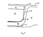
- the pressure can be fairly quickly stepped up to the operating pressure. Almost simultaneously with this increase in pressure to the operating pressure, the charge voltage is applied to deflect the droplets 28 onto the catcher surface, as illustrated in Fig. 4 . The ink 30 then flows around the catcher radius and enters the fluid channel 24. This flow path has much lower pressure drops associated with it, allowing the catcher flow channel to more readily remove ink from the printhead. As a result, the catcher flow channel can now handle the high ink flow that is produced by the increase in the pressure to the operating pressure, without causing the space between the eyelid and catcher to overflow.
- the new high flow rate printhead performs the condensate cleaning of the charge plate at, for example, 138 000 Pa (20 psi) and has an operating pressure of, for example, 193 000 Pa (28 psi).
- the present invention steps the pressure control setpoint up from 138 000 Pa (20 psi) to, for example, 165 000 Pa (24 psi). It has been observed that maintaining pressures above 165 000 Pa (24 psi) will lead to ink overflowing the eyelid.
- the 165 000 Pa (24 psi) condition therefore defines a critical ink removal threshold at or below which the ink removal rate through the catcher will prevent ink overflow.
- the printhead can remain in this 165 000 Pa (24 psi) state, indicated in Fig. 3 as state P1, for extended periods of time, allowing the fluid control servos to stabilize without risk of ink overflowing the eyelid.
- the fluid system remains in this state at least 10 seconds before progressing to the next state. Stabilizing the pressure at state P1, or the exemplary 165 000 Pa (24 psi), reduces the step size required to reach the final operating point. This allows the subsequent step up to the final operating pressure to be more readily achieved, with quicker response and less overshoot.
- the pressure control setpoint can subsequently be stepped up to 193 000 Pa (28 psi). Then, before the fluid system can stabilize at 193 000 Pa (28 psi), the charge voltage is turned on to deflect the ink drops into catch. As mentioned earlier, deflecting the ink drops into catch makes the ink removal process more efficient, so that ink can be removed by the catcher at higher flow rates. By deflecting drops into catch even before the pressure has stabilized at 193 000 Pa (28 psi), the more efficient ink removal process can take effect before the increased flow rates can result in an overflow condition.
- the pressure ramp rate for the transition from 165 000 Pa (24 psi), which is just below the ink removal threshold Pdv, to the operating pressure of 193 000 Pa (28 psi), is modified by inserting a two second state having a target pressure, or pressure setpoint, of 179 000 Pa (26 psi). Since the response rate for the pressure servo is greater than 2 seconds, the insertion of this state in the startup sequence serves to reduce actual rate of pressure increase. It does not cause the pressure to actually be held at 179 000 Pa (26 psi) for any extended length of time. Approximately three seconds after reaching the final operating pressure, the charge voltage is turned on. These state times at the two target pressures are much less than the 8 seconds normally required for the fluid system to stabilize at a new pressure.
- the pressure step size is reduced. Reducing the step size speeds up the actual transition time.
- the approach of the present invention also reduces the amplitude of overshoot and oscillation at the new pressure, thereby reducing the risk of drop deflection variations that could cause charge plate shorts.
Landscapes
- Particle Formation And Scattering Control In Inkjet Printers (AREA)
- Ink Jet (AREA)
Claims (5)
- Procédé de démarrage pour une imprimante à jet d'encre continu, comportant un générateur de gouttes (12), un ensemble de capture (14) et une paupière (16), tous étant associés à un système de fluide, à utiliser au cours du démarrage pour dévier l'encre jusque dans des canaux d'écoulement (24) de l'ensemble de capture, le procédé comprenant les étapes consistant à :déterminer un seuil de pression d'encre (Pdv) pour le générateur de gouttes au-dessus duquel l'encre qui s'écoule en jet depuis le générateur de gouttes et qui est déviée jusque dans les canaux d'écoulement de l'ensemble de capture ne peut pas être enlevée de manière adéquate par les canaux d'écoulement de l'ensemble de capture,augmenter la pression d'encre dans le générateur de gouttes à au moins un état de pression intermédiaire (P1) qui est au seuil de pression d'encre déterminé ou légèrement au-dessous de celui-ci, au cours de la séquence de démarrage,permettre que le système de fluide se stabilise au au moins un état de pression intermédiaire,augmenter la pression d'encre dans le générateur de gouttes jusqu'à un état de pression de fonctionnement finale (P0), etaprès que la pression commence à augmenter jusqu'à la pression de fonctionnement finale et avant que la pression ne se stabilise à la pression de fonctionnement finale, appliquer une tension de charge pour dévier les gouttes d'encre sur le dispositif de capture.
- Procédé de démarrage selon la revendication 1, dans lequel l'étape consistant à appliquer une tension de charge comprend en outre l'étape consistant à appliquer la tension de charge approximativement trois secondes après avoir initié une commande pour atteindre l'état de pression de fonctionnement finale.
- Procédé de démarrage selon la revendication 1, dans lequel l'étape consistant à appliquer une tension de charge comprend en outre l'étape consistant à appliquer une tension de charge initiale inférieure à une tension de charge de fonctionnement.
- Procédé de démarrage selon la revendication 1, comprenant en outre les étapes consistant à :avant l'étape consistant à augmenter la pression d'encre jusqu'au au moins un état de pression intermédiaire, utiliser une paupière pour dévier l'encre dans un canal de fluide associé à l'ensemble de capture tout en maintenant la pression de l'encre à un niveau de pression d'encre bas qui est inférieur à la pression intermédiaire.
- Procédé de démarrage selon la revendication 4, dans lequel la pression intermédiaire est approximativement à mi-chemin entre le niveau de pression d'encre bas et la pression de fonctionnement finale.
Applications Claiming Priority (2)
| Application Number | Priority Date | Filing Date | Title |
|---|---|---|---|
| US254353 | 1994-06-06 | ||
| US10/254,353 US6688733B1 (en) | 2002-09-25 | 2002-09-25 | Rapid pressure ramp startup |
Publications (2)
| Publication Number | Publication Date |
|---|---|
| EP1403060A1 EP1403060A1 (fr) | 2004-03-31 |
| EP1403060B1 true EP1403060B1 (fr) | 2008-09-24 |
Family
ID=30770698
Family Applications (1)
| Application Number | Title | Priority Date | Filing Date |
|---|---|---|---|
| EP03255926A Expired - Lifetime EP1403060B1 (fr) | 2002-09-25 | 2003-09-23 | Démarrage à rampe de pression rapide |
Country Status (3)
| Country | Link |
|---|---|
| US (1) | US6688733B1 (fr) |
| EP (1) | EP1403060B1 (fr) |
| DE (1) | DE60323715D1 (fr) |
Families Citing this family (3)
| Publication number | Priority date | Publication date | Assignee | Title |
|---|---|---|---|---|
| US6736498B2 (en) * | 2002-09-25 | 2004-05-18 | Eastman Kodak Company | Eyelid positioning |
| US7331658B2 (en) | 2006-06-19 | 2008-02-19 | Eastman Kodak Company | Anti-wicking catcher assembly and printing system |
| CN116458837B (zh) * | 2023-04-24 | 2023-09-19 | 首都医科大学附属北京同仁医院 | 眼睑力测量方法 |
Family Cites Families (12)
| Publication number | Priority date | Publication date | Assignee | Title |
|---|---|---|---|---|
| US4122458A (en) * | 1977-08-19 | 1978-10-24 | The Mead Corporation | Ink jet printer having plural parallel deflection fields |
| US4286272A (en) * | 1979-08-13 | 1981-08-25 | The Mead Corporation | Ink jet printer and start up method therefor |
| US4250510A (en) * | 1979-09-04 | 1981-02-10 | The Mead Corporation | Fluid jet device |
| US4399446A (en) * | 1982-01-18 | 1983-08-16 | The Mead Corporation | Ink supply system for an ink jet printer |
| US4404566A (en) * | 1982-03-08 | 1983-09-13 | The Mead Corporation | Fluid system for fluid jet printing device |
| US4514735A (en) * | 1983-08-12 | 1985-04-30 | The Mead Corporation | Ink jet printer start-up and shutdown |
| US4928113A (en) * | 1988-10-31 | 1990-05-22 | Eastman Kodak Company | Constructions and fabrication methods for drop charge/deflection in continuous ink jet printer |
| GB8829620D0 (en) * | 1988-12-20 | 1989-02-15 | Elmjet Ltd | Continuous ink jet printer |
| US5801734A (en) * | 1995-12-22 | 1998-09-01 | Scitex Digital Printing, Inc. | Two row flat face charging for high resolution printing |
| US6247781B1 (en) * | 1998-12-14 | 2001-06-19 | Scitex Digital Printing, Inc. | Ink jet printhead with an improved eyelid system |
| US6187212B1 (en) | 1998-12-14 | 2001-02-13 | Scitex Digital Printing, Inc. | Device for balanced uniform flow and simplified construction to remove fluid from an ink jet printer |
| US6527363B1 (en) * | 2001-07-27 | 2003-03-04 | Scitex Digital Printing, Inc. | Low profile disposable polymer wicking pad |
-
2002
- 2002-09-25 US US10/254,353 patent/US6688733B1/en not_active Expired - Fee Related
-
2003
- 2003-09-23 DE DE60323715T patent/DE60323715D1/de not_active Expired - Lifetime
- 2003-09-23 EP EP03255926A patent/EP1403060B1/fr not_active Expired - Lifetime
Also Published As
| Publication number | Publication date |
|---|---|
| EP1403060A1 (fr) | 2004-03-31 |
| US6688733B1 (en) | 2004-02-10 |
| DE60323715D1 (de) | 2008-11-06 |
Similar Documents
| Publication | Publication Date | Title |
|---|---|---|
| US11230097B2 (en) | Fluid ejection device | |
| US5757391A (en) | High-frequency drop-on-demand ink jet system | |
| KR101686286B1 (ko) | 순환 펌프를 구비한 유체 분사 어셈블리 | |
| EP0029696B1 (fr) | Imprimante à jet d'encre | |
| KR101797266B1 (ko) | 인쇄 시스템 및 관련 방법 | |
| US10632749B2 (en) | Fluid ejection device | |
| US10183493B2 (en) | Fluid ejection device | |
| KR100218558B1 (ko) | 잉크젯 프린터 및 그 제어방법 | |
| JP2001179983A (ja) | 連続インクジェットプリンタのインクの偏向制御装置及び偏向改善方法 | |
| KR20130113919A (ko) | 유체 분사 장치 | |
| EP1403060B1 (fr) | Démarrage à rampe de pression rapide | |
| EP0044751B1 (fr) | Système et dispositif à jet d'encre et méthode pour prévenir une fuite de fluide d'une tête d'impression à jet d'encre après arrêt | |
| US6962411B2 (en) | Anti-wicking catcher arrangement for a solvent ink printhead | |
| EP1403071B1 (fr) | Système à action de mèche pour un collecteur d'encre | |
| JPS63139749A (ja) | インクジエツト記録ヘツド | |
| US6513895B2 (en) | Increased startup pulse warming temperature to improve pen startup reliability | |
| EP1435293B1 (fr) | Mise en marche automatique pour un système d'impression à encre de solvant | |
| US6450609B1 (en) | Methods for charging and priming fluid ejector heads | |
| JP3572866B2 (ja) | インクジェット記録装置およびその制御方法 | |
| EP1403048B1 (fr) | Démarrage avec une tension d'interception basse | |
| JPH01285355A (ja) | インクジェット記録装置 | |
| EP2915672B1 (fr) | Appareil et procédé permettant d'éjecter des gouttelettes | |
| US20250326233A1 (en) | Ink storage device for multi-head inkjet printer and multi-head ink-jet printer including same | |
| JPH07314703A (ja) | 連続型インクジェットプリンタ用ヘッド | |
| JP2025004574A (ja) | 印刷装置、印刷方法及びコンピュータプログラム |
Legal Events
| Date | Code | Title | Description |
|---|---|---|---|
| PUAI | Public reference made under article 153(3) epc to a published international application that has entered the european phase |
Free format text: ORIGINAL CODE: 0009012 |
|
| AK | Designated contracting states |
Kind code of ref document: A1 Designated state(s): AT BE BG CH CY CZ DE DK EE ES FI FR GB GR HU IE IT LI LU MC NL PT RO SE SI SK TR |
|
| AX | Request for extension of the european patent |
Extension state: AL LT LV MK |
|
| RAP1 | Party data changed (applicant data changed or rights of an application transferred) |
Owner name: EASTMAN KODAK COMPANY |
|
| 17P | Request for examination filed |
Effective date: 20040911 |
|
| AKX | Designation fees paid |
Designated state(s): DE FR GB |
|
| 17Q | First examination report despatched |
Effective date: 20070508 |
|
| GRAP | Despatch of communication of intention to grant a patent |
Free format text: ORIGINAL CODE: EPIDOSNIGR1 |
|
| GRAS | Grant fee paid |
Free format text: ORIGINAL CODE: EPIDOSNIGR3 |
|
| GRAA | (expected) grant |
Free format text: ORIGINAL CODE: 0009210 |
|
| AK | Designated contracting states |
Kind code of ref document: B1 Designated state(s): DE FR GB |
|
| REG | Reference to a national code |
Ref country code: GB Ref legal event code: FG4D |
|
| REF | Corresponds to: |
Ref document number: 60323715 Country of ref document: DE Date of ref document: 20081106 Kind code of ref document: P |
|
| PLBE | No opposition filed within time limit |
Free format text: ORIGINAL CODE: 0009261 |
|
| STAA | Information on the status of an ep patent application or granted ep patent |
Free format text: STATUS: NO OPPOSITION FILED WITHIN TIME LIMIT |
|
| 26N | No opposition filed |
Effective date: 20090625 |
|
| PGFP | Annual fee paid to national office [announced via postgrant information from national office to epo] |
Ref country code: FR Payment date: 20120910 Year of fee payment: 10 |
|
| PGFP | Annual fee paid to national office [announced via postgrant information from national office to epo] |
Ref country code: GB Payment date: 20130827 Year of fee payment: 11 |
|
| REG | Reference to a national code |
Ref country code: FR Ref legal event code: ST Effective date: 20140530 |
|
| PG25 | Lapsed in a contracting state [announced via postgrant information from national office to epo] |
Ref country code: FR Free format text: LAPSE BECAUSE OF NON-PAYMENT OF DUE FEES Effective date: 20130930 |
|
| PGFP | Annual fee paid to national office [announced via postgrant information from national office to epo] |
Ref country code: DE Payment date: 20140930 Year of fee payment: 12 |
|
| GBPC | Gb: european patent ceased through non-payment of renewal fee |
Effective date: 20140923 |
|
| PG25 | Lapsed in a contracting state [announced via postgrant information from national office to epo] |
Ref country code: GB Free format text: LAPSE BECAUSE OF NON-PAYMENT OF DUE FEES Effective date: 20140923 |
|
| REG | Reference to a national code |
Ref country code: DE Ref legal event code: R119 Ref document number: 60323715 Country of ref document: DE |
|
| PG25 | Lapsed in a contracting state [announced via postgrant information from national office to epo] |
Ref country code: DE Free format text: LAPSE BECAUSE OF NON-PAYMENT OF DUE FEES Effective date: 20160401 |