EP1403077A1 - Dispositif à l'éclairage linéaire - Google Patents
Dispositif à l'éclairage linéaire Download PDFInfo
- Publication number
- EP1403077A1 EP1403077A1 EP02021184A EP02021184A EP1403077A1 EP 1403077 A1 EP1403077 A1 EP 1403077A1 EP 02021184 A EP02021184 A EP 02021184A EP 02021184 A EP02021184 A EP 02021184A EP 1403077 A1 EP1403077 A1 EP 1403077A1
- Authority
- EP
- European Patent Office
- Prior art keywords
- light sources
- point light
- lines
- light
- line
- Prior art date
- Legal status (The legal status is an assumption and is not a legal conclusion. Google has not performed a legal analysis and makes no representation as to the accuracy of the status listed.)
- Withdrawn
Links
- 238000005286 illumination Methods 0.000 title abstract description 11
- 230000003287 optical effect Effects 0.000 claims abstract description 17
- 230000005855 radiation Effects 0.000 claims abstract description 4
- 210000001747 pupil Anatomy 0.000 claims description 11
- 238000003384 imaging method Methods 0.000 claims description 6
- 239000013307 optical fiber Substances 0.000 claims description 3
- 238000001914 filtration Methods 0.000 claims description 2
- 238000013507 mapping Methods 0.000 claims 1
- 238000002156 mixing Methods 0.000 description 3
- 230000000694 effects Effects 0.000 description 2
- 238000000265 homogenisation Methods 0.000 description 2
- 239000003086 colorant Substances 0.000 description 1
- 238000010276 construction Methods 0.000 description 1
- 238000004519 manufacturing process Methods 0.000 description 1
- 238000000034 method Methods 0.000 description 1
- 238000009827 uniform distribution Methods 0.000 description 1
Images


Classifications
-
- H—ELECTRICITY
- H04—ELECTRIC COMMUNICATION TECHNIQUE
- H04N—PICTORIAL COMMUNICATION, e.g. TELEVISION
- H04N1/00—Scanning, transmission or reproduction of documents or the like, e.g. facsimile transmission; Details thereof
- H04N1/024—Details of scanning heads ; Means for illuminating the original
- H04N1/028—Details of scanning heads ; Means for illuminating the original for picture information pick-up
- H04N1/02815—Means for illuminating the original, not specific to a particular type of pick-up head
-
- B—PERFORMING OPERATIONS; TRANSPORTING
- B41—PRINTING; LINING MACHINES; TYPEWRITERS; STAMPS
- B41J—TYPEWRITERS; SELECTIVE PRINTING MECHANISMS, i.e. MECHANISMS PRINTING OTHERWISE THAN FROM A FORME; CORRECTION OF TYPOGRAPHICAL ERRORS
- B41J2/00—Typewriters or selective printing mechanisms characterised by the printing or marking process for which they are designed
- B41J2/435—Typewriters or selective printing mechanisms characterised by the printing or marking process for which they are designed characterised by selective application of radiation to a printing material or impression-transfer material
- B41J2/447—Typewriters or selective printing mechanisms characterised by the printing or marking process for which they are designed characterised by selective application of radiation to a printing material or impression-transfer material using arrays of radiation sources
- B41J2/45—Typewriters or selective printing mechanisms characterised by the printing or marking process for which they are designed characterised by selective application of radiation to a printing material or impression-transfer material using arrays of radiation sources using light-emitting diode [LED] or laser arrays
- B41J2/451—Special optical means therefor, e.g. lenses, mirrors, focusing means
-
- G—PHYSICS
- G02—OPTICS
- G02B—OPTICAL ELEMENTS, SYSTEMS OR APPARATUS
- G02B27/00—Optical systems or apparatus not provided for by any of the groups G02B1/00 - G02B26/00, G02B30/00
- G02B27/10—Beam splitting or combining systems
- G02B27/1006—Beam splitting or combining systems for splitting or combining different wavelengths
- G02B27/102—Beam splitting or combining systems for splitting or combining different wavelengths for generating a colour image from monochromatic image signal sources
-
- G—PHYSICS
- G02—OPTICS
- G02B—OPTICAL ELEMENTS, SYSTEMS OR APPARATUS
- G02B27/00—Optical systems or apparatus not provided for by any of the groups G02B1/00 - G02B26/00, G02B30/00
- G02B27/10—Beam splitting or combining systems
- G02B27/12—Beam splitting or combining systems operating by refraction only
- G02B27/123—The splitting element being a lens or a system of lenses, including arrays and surfaces with refractive power
-
- H—ELECTRICITY
- H04—ELECTRIC COMMUNICATION TECHNIQUE
- H04N—PICTORIAL COMMUNICATION, e.g. TELEVISION
- H04N1/00—Scanning, transmission or reproduction of documents or the like, e.g. facsimile transmission; Details thereof
- H04N1/024—Details of scanning heads ; Means for illuminating the original
- H04N1/028—Details of scanning heads ; Means for illuminating the original for picture information pick-up
- H04N1/02815—Means for illuminating the original, not specific to a particular type of pick-up head
- H04N1/0288—Means for illuminating the original, not specific to a particular type of pick-up head using a two-dimensional light source, e.g. two-dimensional LED array
-
- H—ELECTRICITY
- H04—ELECTRIC COMMUNICATION TECHNIQUE
- H04N—PICTORIAL COMMUNICATION, e.g. TELEVISION
- H04N1/00—Scanning, transmission or reproduction of documents or the like, e.g. facsimile transmission; Details thereof
- H04N1/024—Details of scanning heads ; Means for illuminating the original
- H04N1/028—Details of scanning heads ; Means for illuminating the original for picture information pick-up
- H04N1/02815—Means for illuminating the original, not specific to a particular type of pick-up head
- H04N1/02895—Additional elements in the illumination means or cooperating with the illumination means, e.g. filters
Definitions
- the invention relates to a device according to the preamble of claim 1 for the linear illumination of a surface with light of different wavelengths.
- a device of the type mentioned at the outset is used, for example, in scanning devices in order to illuminate a surface in which, for example, a scanning unit is arranged, in rows.
- elongated light sources such as fluorescent tubes
- the light of which is homogenized by optical devices, for example diffusers, lenses and the like.
- spectrally separated light sources for example LEDs or laser diodes
- their light beams must be superimposed in a beam path by complex dichroic optical devices.
- No. 5,537,229 discloses a device for scanning colored originals, in which separate light sources are used for each color, the light rays of which can be brought together in a beam path via partially transparent optical elements.
- Such partially permeable elements are, however, very expensive and must be positioned precisely with respect to one another, in particular for adequate light quality, for which purpose correspondingly complex adjustment devices must be provided on the device.
- a light source for scanning devices is known from US Pat. No. 6,299,329, in which a multiplicity of point light sources, which differ from one another in terms of the wavelength range emitted by them, are arranged in a row arrangement, mixed.
- the mixed, line-by-line arrangement of the spectrally separated point light sources is intended to achieve uniform illumination with light of different wavelengths.
- the type of arrangement of the point light sources leads to insufficient light mixing, which results in only moderate homogeneity of illumination.
- the mixed arrangement of the spectrally separated point light sources means that different wavelength ranges can only be filtered out using complex mosaic filters.
- US 6 042 013 discloses a device for the linear illumination of a scanning unit with light of different wavelengths, in which light from separate light sources is mixed in a light mixer and projected onto the scanning unit to be illuminated.
- a light mixer is very complex to manufacture and must be positioned with high accuracy in relation to the light sources so that the desired effect can be achieved.
- the invention solves the problem by a device with the features of claim 1.
- a multiplicity of point light sources are in each case combined in common lines and arranged side by side.
- the point light sources arranged side by side in a common line can either emit light of the same wavelength or light of different wavelengths.
- a lens is arranged in front of each line of point light sources arranged next to one another, which detects, bundles and directs the light beams emitted by the point light sources of this line and guides them into the entrance pupil of the field lens arranged downstream.
- the light beams emitted by the point light sources are already brought together by the shape and arrangement of the aspherical lens assigned to them in such a way that the individual light beams emitted by the point light sources are homogenized.
- each aspherical lens is then passed on to the field lens, in which the individual light beams of the aspherical lenses are brought together and further homogenized.
- the resulting homogeneous light beam is then projected onto the surface in order to illuminate it, which results in a homogeneity of illumination which is comparable with the prior art and has a greatly simplified structure.
- the light beams of the point light source rows are combined according to the invention by selecting the distance between the rows of the point light sources arranged next to one another to be greater than the distance between the optical axes between the aspherical lenses arranged next to one another, so that at least some of the aspherical lenses with their optical axes are offset the rows assigned to these are arranged.
- This offset arrangement between the point light sources and the aspherical lenses assigned to them ensures that the light emitted by the point light sources of each line is detected by the entrance pupils of the aspherical lenses on the one hand and the detected light is deflected into the entrance pupil in a predetermined direction on the other hand.
- the distance of the point light sources of each line to the aspherical lens assigned to the respective line is preferred, the focal length of this assigned aspherical lens
- the lens and the distance of the respective aspherical lens to the entrance pupil of the field lens are designed in such a way that the point light sources of the row completely illuminate the entrance pupil of the field lens in a row.
- the light losses are minimized by this optimized arrangement of the point light sources of each line to the aspherical lenses assigned to them as well as by the targeted selection of the focal length of these lenses and the distance of the lenses from the entrance pupil of the field lens.
- Cylindrical lenses or toric lenses are preferably used as aspherical lenses.
- the cylindrical lens is characterized in particular by the fact that the light in the plane of the cylindrical lens axis is particularly well homogenized due to the light mixing that occurs. In the case of the toric lenses, the homogenization takes place through the light mixing in the plane with the larger lens radius.
- the point light sources arranged in a common line are particularly preferably combined into a group and emit light of the same wavelengths. This enables a simple control of the individual colors. Furthermore, the filtering of such lines from identically designed point light sources is comparatively simple.
- the distance between point light sources and cylindrical or toric lenses is chosen to be at least so large that the lenses are completely illuminated.
- the lenses appear as a homogeneous light source that can be imaged homogeneously by the field lens.
- the inhomogeneity of individual luminous points can be overcome in this way.
- the device particularly preferably generates blue light with wavelengths in a range from approximately 420 to 510 nm, green light with wavelengths in a range from approximately 510 to 585 nm and red light with wavelengths in a range from approximately 585 to 780 nm.
- point light sources can also be used which emit infrared light with wavelengths in a range from approximately 780 nm to 1 mm onto the surface.
- LEDs or laser diodes which are very switchable and can generate light with high light intensity are preferably used as point light sources.
- the device In order to facilitate the control of the individual point light sources of the device, it is proposed in a particularly preferred embodiment of the device to combine the point light sources that emit light of the same wavelengths into groups which are to be controlled together. It is then possible to control the groups of different wavelength ranges in a simple manner sequentially or in parallel.
- point light sources usually emit light with a larger wavelength range
- a filter unit with filters between the aspherical lens and the point light sources that filter out wavelength ranges with which the surface is not to be illuminated.
- the device according to the invention As a particularly preferred area of application, it is proposed to design the device according to the invention as a scanning device in which a scanning unit, preferably a CCD unit, is arranged in the surface to be illuminated. With the aid of the field lens, the light emitted by the point light sources is then directed through a template to be scanned, for example an image template, the image of which is imaged on the scanning unit.
- a scanning unit preferably a CCD unit
- this scanning device it is also proposed to arrange an imaging optical system between the original and the scanning unit, with which the original can be projected onto the scanning unit.
- the device of the invention is suitable as a line light for line modulators, in particular as a line light for GLV lines (G rating L ight V alve), PLZT lines (lead (Pb) - L anthan- Z irkonium- T itanat), DMD Lines ( D igital M icromirror D evice), LCD lines or optical fiber lines. It can therefore be used advantageously in scanners as well as in printers.
- GLV lines G rating L ight V alve
- PLZT lines lead (Pb) - L anthan- Z irkonium- T itanat
- DMD Lines D igital M icromirror D evice
- LCD lines or optical fiber lines or optical fiber lines. It can therefore be used advantageously in scanners as well as in printers.
- FIG 1 and 2 are a schematic illustration of a side view and a top view of a device 10 for linear illumination, which is used in the present case as a scanning device.
- the device 10 has a light source 12, which is followed by an optical device 14 in the radiation direction A.
- the optical device 14 homogenizes the light emitted by the light source 12 and guides it through a film stage 16, in which a template (not shown, to be scanned) is to be positioned, into the entrance pupil of an imaging optics 18.
- the imaging optics 18 projects this from the optical device 14 the original emitted light onto a scanning unit 20, which in the present case is designed as a CCD line.
- the light source 12 is formed from a plurality of lines 22a, 22b and 22c arranged next to one another in parallel in a common plane.
- Each line 22a, 22b and 22c has a predetermined number of point light sources 24a, 24b and 24c.
- Lines 22a, 22b and 22c are essentially identical formed and differ only in the wavelength ranges of the light emitted by the respective point light sources 24a, 24b and 24c.
- Lines 22a emit blue light with wavelengths in a range from approximately 420 to 510 nm
- lines 22b emit green light with wavelengths in a range from approximately 510 to 585 nm.
- the numbers 22c on the other hand, emit red light with wavelengths in a range from approximately 585 to 780 nm.
- the individual lines 22a, 22b and 22c are arranged relative to one another such that a line 22a, 22b or 22c for emitting light of a predetermined wavelength range is arranged next to a line 22b, 22c or 22a which emits light of another wavelength range ,
- This successive, alternating arrangement of the lines 22a, 22b and 22c results in a uniform distribution of light of different wavelength ranges over the entire area of the light source 12.
- the individual lines 22a, 22b and 22c which emit light of the same wavelength, are combined into groups and can be controlled and set separately from the other lines 22a, 22b and 22c.
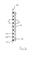
- FIG. 4 shows, in which a side view of the light source 12 shown in FIG. 3 is shown, a number of lines 22a, 22b and 22c corresponding to the number of lines 22a, 22b and 22c are parallel to one another with a predetermined distance E (cf. also FIG. 1) arranged cylindrical lenses 26 arranged in a plane parallel to the light source 12. Each line 22a, 22b or 22c is assigned one of the cylindrical lenses 26.
- the line 22b which is arranged in the plane in which the main optical axis H of the optical device 14 lies, is positioned centrally with respect to the cylindrical lens 26 assigned to it.
- the distance x between the lines 22a, c adjacent to this line 22b is, however, selected such that it is somewhat larger than the distance y between the cylinder lenses 26 assigned to them. This results in a predetermined offset between the lines 22a, b, arranged next to one another. c and the cylinder lenses 26 respectively assigned to them. This offset ensures that the radiation emitted by the point light sources 24 in Direction of the field lens 28 directed light 30 is superimposed on the template line, as shown in particular in FIG. 1.
- the distance E of the point light sources 24 of each line 22 to the aspherical lens 26 assigned to the respective line, the focal length of the respective aspherical lens 26 and the distance F of the aspherical lenses 26 from the entrance pupil of the field lens 28 are selected such that the light from the point light sources 24 of the various lines 22 are superimposed in the entrance pupil of the field lens 28, so that the field lens 28 is completely illuminated in a row.
- the field lens 28 With this homogenized light beam, the field lens 28 in turn illuminates the original positioned in the film stage 16, the image of which is projected onto the scanning unit 20 through the imaging optics 18.
- the scanning unit 20 generates corresponding image information based on the image of the original, which can be used for a subsequent exposure process, for example.
- the light rays 30 emitted by the point light sources 24 are combined by the shape of the aspherical lenses 26 and by the staggered arrangement of the lenses 26 to form lines 22 such that the individual light rays 30 emitted by the point light sources 24 are homogenized in the respective aspherical Lens 26 occurs.
- the light which has already been homogenized in this way by the aspherical lenses 26 is then passed on to the field lens 28, from which the individual light beams 30 of the aspherical lenses 26 illuminate the original line in a superimposed manner. In this way, a very homogeneous and uniform illumination of the original and the scanning unit 20 with light composed of different wavelength ranges can be achieved in a simple manner.
- the device described above in particular the optical device 14 according to the invention described above, can be used for a wide variety of purposes.
- the device 10 according to the invention is also suitable, for example, as line lighting for line modulators, such as GLV lines, PLZT lines, DMD lines, LCD lines or optical fiber lines. 4 sheets of drawings
Landscapes
- Physics & Mathematics (AREA)
- Engineering & Computer Science (AREA)
- Multimedia (AREA)
- Signal Processing (AREA)
- Optics & Photonics (AREA)
- General Physics & Mathematics (AREA)
- Health & Medical Sciences (AREA)
- General Health & Medical Sciences (AREA)
- Toxicology (AREA)
- Mechanical Optical Scanning Systems (AREA)
Priority Applications (1)
| Application Number | Priority Date | Filing Date | Title |
|---|---|---|---|
| EP02021184A EP1403077A1 (fr) | 2002-09-24 | 2002-09-24 | Dispositif à l'éclairage linéaire |
Applications Claiming Priority (1)
| Application Number | Priority Date | Filing Date | Title |
|---|---|---|---|
| EP02021184A EP1403077A1 (fr) | 2002-09-24 | 2002-09-24 | Dispositif à l'éclairage linéaire |
Publications (1)
| Publication Number | Publication Date |
|---|---|
| EP1403077A1 true EP1403077A1 (fr) | 2004-03-31 |
Family
ID=31970294
Family Applications (1)
| Application Number | Title | Priority Date | Filing Date |
|---|---|---|---|
| EP02021184A Withdrawn EP1403077A1 (fr) | 2002-09-24 | 2002-09-24 | Dispositif à l'éclairage linéaire |
Country Status (1)
| Country | Link |
|---|---|
| EP (1) | EP1403077A1 (fr) |
Cited By (5)
| Publication number | Priority date | Publication date | Assignee | Title |
|---|---|---|---|---|
| US7498597B2 (en) | 2006-08-31 | 2009-03-03 | Agfa Healthcare N.V. | Storage phosphor layer and system and method for erasing same |
| US7507984B2 (en) | 2006-08-31 | 2009-03-24 | Agfa Healthcare N.V. | Storage phosphor layer and system and method for erasing same |
| US7633078B2 (en) | 2006-08-31 | 2009-12-15 | Agfa Healthcare Nv | Storage phosphor layer and system and method for erasing same |
| WO2013164053A1 (fr) * | 2012-05-02 | 2013-11-07 | Heraeus Noblelight Gmbh | Dispositif d'éclairage à del et à lentille cylindrique |
| WO2020120460A3 (fr) * | 2018-12-14 | 2020-08-13 | Heraeus Noblelight Gmbh | Appareil d'éclairage pour exposer une cible à un rayonnement |
Citations (7)
| Publication number | Priority date | Publication date | Assignee | Title |
|---|---|---|---|---|
| US5537229A (en) | 1990-04-20 | 1996-07-16 | Nikon Corporation | Method and apparatus for rapid scanning of color images |
| US5954424A (en) * | 1995-10-25 | 1999-09-21 | Texas Instruments Incorporated | Illumination system for hard copy apparatus |
| US6042013A (en) | 1997-11-17 | 2000-03-28 | Xerox Corporation | Multi-colored illuminator apparatus for a scanner device |
| US6144685A (en) * | 1996-01-23 | 2000-11-07 | Fuji Xerox Co., Ltd. | Two-dimensional surface emitting laser array, two-dimensional surface emitting laser beam scanner, two-dimensional surface emitting laser beam recorder, and two-dimensional surface emitting laser beam recording method |
| US6188086B1 (en) * | 1995-11-10 | 2001-02-13 | Ricoh Company, Ltd. | Light emitting diode array and optical image forming apparatus with light emitting diode array |
| US6208369B1 (en) * | 1996-08-20 | 2001-03-27 | Creoscitex Corporation Ltd. | Apparatus and method for recording an image |
| US6299329B1 (en) | 1999-02-23 | 2001-10-09 | Hewlett-Packard Company | Illumination source for a scanner having a plurality of solid state lamps and a related method |
-
2002
- 2002-09-24 EP EP02021184A patent/EP1403077A1/fr not_active Withdrawn
Patent Citations (7)
| Publication number | Priority date | Publication date | Assignee | Title |
|---|---|---|---|---|
| US5537229A (en) | 1990-04-20 | 1996-07-16 | Nikon Corporation | Method and apparatus for rapid scanning of color images |
| US5954424A (en) * | 1995-10-25 | 1999-09-21 | Texas Instruments Incorporated | Illumination system for hard copy apparatus |
| US6188086B1 (en) * | 1995-11-10 | 2001-02-13 | Ricoh Company, Ltd. | Light emitting diode array and optical image forming apparatus with light emitting diode array |
| US6144685A (en) * | 1996-01-23 | 2000-11-07 | Fuji Xerox Co., Ltd. | Two-dimensional surface emitting laser array, two-dimensional surface emitting laser beam scanner, two-dimensional surface emitting laser beam recorder, and two-dimensional surface emitting laser beam recording method |
| US6208369B1 (en) * | 1996-08-20 | 2001-03-27 | Creoscitex Corporation Ltd. | Apparatus and method for recording an image |
| US6042013A (en) | 1997-11-17 | 2000-03-28 | Xerox Corporation | Multi-colored illuminator apparatus for a scanner device |
| US6299329B1 (en) | 1999-02-23 | 2001-10-09 | Hewlett-Packard Company | Illumination source for a scanner having a plurality of solid state lamps and a related method |
Cited By (13)
| Publication number | Priority date | Publication date | Assignee | Title |
|---|---|---|---|---|
| US7498597B2 (en) | 2006-08-31 | 2009-03-03 | Agfa Healthcare N.V. | Storage phosphor layer and system and method for erasing same |
| US7507984B2 (en) | 2006-08-31 | 2009-03-24 | Agfa Healthcare N.V. | Storage phosphor layer and system and method for erasing same |
| US7633078B2 (en) | 2006-08-31 | 2009-12-15 | Agfa Healthcare Nv | Storage phosphor layer and system and method for erasing same |
| TWI495826B (zh) * | 2012-05-02 | 2015-08-11 | 賀利氏諾伯燈具公司 | 具有發光二極體(led)及圓柱型透鏡之燈 |
| KR20140144721A (ko) * | 2012-05-02 | 2014-12-19 | 헤레우스 노블라이트 게엠베하 | Led 및 원주 렌즈를 갖춘 조명 기구 |
| CN104396012A (zh) * | 2012-05-02 | 2015-03-04 | 贺利氏特种光源有限责任公司 | 具有led和圆柱形透镜的发光体 |
| WO2013164053A1 (fr) * | 2012-05-02 | 2013-11-07 | Heraeus Noblelight Gmbh | Dispositif d'éclairage à del et à lentille cylindrique |
| US9695992B2 (en) | 2012-05-02 | 2017-07-04 | Heraeus Noblelight Gmbh | Luminaire with LEDs and cylindrical lens |
| EP3396713A1 (fr) * | 2012-05-02 | 2018-10-31 | Heraeus Noblelight GmbH | Dispositif d'éclairage à led et à lentille cylindrique |
| CN104396012B (zh) * | 2012-05-02 | 2018-12-04 | 贺利氏特种光源有限责任公司 | 具有led和圆柱形透镜的发光体 |
| CN109973840A (zh) * | 2012-05-02 | 2019-07-05 | 贺利氏特种光源有限责任公司 | 具有led和圆柱形透镜的发光体 |
| CN109973840B (zh) * | 2012-05-02 | 2021-06-01 | 贺利氏特种光源有限责任公司 | 具有led和圆柱形透镜的发光体 |
| WO2020120460A3 (fr) * | 2018-12-14 | 2020-08-13 | Heraeus Noblelight Gmbh | Appareil d'éclairage pour exposer une cible à un rayonnement |
Similar Documents
| Publication | Publication Date | Title |
|---|---|---|
| EP1528421B1 (fr) | Stéréomicroscope avec un system d'éclairage à diodes électroluminescentes | |
| EP2136248B1 (fr) | Dispositif d'enregistrement d'images avec illumination adaptatif | |
| DE69626851T2 (de) | Beleuchtungssystem zum optischen lesen von merkmalen auf einem substrat | |
| DE19751106A1 (de) | Laserdrucker zum Drucken auf ein lichtempfindliches Medium | |
| EP1403695A1 (fr) | Dispositif d'exposition d'un original comprenant une pluralité de sources lumineuses ponctuelles homogenisées et superposées | |
| EP3608585A1 (fr) | Dispositif de projection d'un grand nombre de systèmes micro-optiques et module d'éclairage de phare de véhicule automobile | |
| DE102020203506A1 (de) | Wellenlängenumwandlungselement, lichtquellenvorrichtung und beleuchtungsvorrichtung | |
| DE10230652A1 (de) | Optische Vorrichtung mit einer Beleuchtungslichtquelle | |
| EP2261717A1 (fr) | Agencement de sources lumineuses pour un dispositif d'éclairage d'un appareil d'observation optique médical | |
| EP1591825A3 (fr) | Dispositif de couplage de la lumière dans le parcours de la lumière d'un microscope | |
| DE102010031678B4 (de) | Schnelle, variable Einfallswinkelbeleuchtung für Maschinensichtinspektionssystem | |
| DE1165303B (de) | Optisches Bilduebertragungssystem | |
| DE102012208016A1 (de) | Beleuchtungsoptik für die Mikrolithographie | |
| DE2409924A1 (de) | Vorrichtung zur herstellung einer vielfalt von projektionsbildern | |
| DE112007001551T5 (de) | Verfahren und Vorrichtung zum Aufbringen von Mustern aus nicht zusammenhängenden Merkmalen | |
| EP1259846B1 (fr) | Procede et dispositif de reglage d'un appareil photographique | |
| EP1470778B1 (fr) | Dispositif de projection d'un faisceau lumineux | |
| EP1403077A1 (fr) | Dispositif à l'éclairage linéaire | |
| DE102005031647A1 (de) | Beleuchtungsvorrichtung zur Dunkelfeldbeleuchtung für eine optische Testvorrichtung und Verfahren zum optischen Abtasten eines Objektes | |
| EP1664892A1 (fr) | Micro-endoscope confocal comprenant des fibres optiques a diametre decroissant | |
| WO1994007170A1 (fr) | Dispositif d'eclairage a fond clair et par transparence pour microscopes | |
| EP1380885A1 (fr) | Dispositif et procédé pour imprimer des images numériques sur matériaux photosensibles | |
| DE102020210592A1 (de) | Verfahren und Mikroskop zum Erzeugen einer artefaktreduzierten Übersichtsaufnahme eines Probenträgers | |
| DE2024366B2 (de) | Lichtsetzmaschine | |
| DE102018123381A1 (de) | Verfahren und Vorrichtung zum Abrastern einer Probe |
Legal Events
| Date | Code | Title | Description |
|---|---|---|---|
| PUAI | Public reference made under article 153(3) epc to a published international application that has entered the european phase |
Free format text: ORIGINAL CODE: 0009012 |
|
| AK | Designated contracting states |
Kind code of ref document: A1 Designated state(s): AT BE BG CH CY CZ DE DK EE ES FI FR GB GR IE IT LI LU MC NL PT SE SK TR |
|
| AX | Request for extension of the european patent |
Extension state: AL LT LV MK RO SI |
|
| 17P | Request for examination filed |
Effective date: 20040930 |
|
| AKX | Designation fees paid |
Designated state(s): AT BE BG CH CY CZ DE DK EE ES FI FR GB GR IE IT LI LU MC NL PT SE SK TR |
|
| 17Q | First examination report despatched |
Effective date: 20050125 |
|
| RAP1 | Party data changed (applicant data changed or rights of an application transferred) |
Owner name: AGFAPHOTO GMBH |
|
| 19U | Interruption of proceedings before grant |
Effective date: 20060101 |
|
| 19W | Proceedings resumed before grant after interruption of proceedings |
Effective date: 20100401 |
|
| STAA | Information on the status of an ep patent application or granted ep patent |
Free format text: STATUS: THE APPLICATION IS DEEMED TO BE WITHDRAWN |
|
| 18D | Application deemed to be withdrawn |
Effective date: 20060401 |