EP1403082B1 - Dispositif ayant une fonction d'impression - Google Patents
Dispositif ayant une fonction d'impression Download PDFInfo
- Publication number
- EP1403082B1 EP1403082B1 EP03256143A EP03256143A EP1403082B1 EP 1403082 B1 EP1403082 B1 EP 1403082B1 EP 03256143 A EP03256143 A EP 03256143A EP 03256143 A EP03256143 A EP 03256143A EP 1403082 B1 EP1403082 B1 EP 1403082B1
- Authority
- EP
- European Patent Office
- Prior art keywords
- sheet
- printing
- paper
- feeding
- produced
- Prior art date
- Legal status (The legal status is an assumption and is not a legal conclusion. Google has not performed a legal analysis and makes no representation as to the accuracy of the status listed.)
- Expired - Lifetime
Links
Images



Classifications
-
- G—PHYSICS
- G03—PHOTOGRAPHY; CINEMATOGRAPHY; ANALOGOUS TECHNIQUES USING WAVES OTHER THAN OPTICAL WAVES; ELECTROGRAPHY; HOLOGRAPHY
- G03G—ELECTROGRAPHY; ELECTROPHOTOGRAPHY; MAGNETOGRAPHY
- G03G15/00—Apparatus for electrographic processes using a charge pattern
-
- B—PERFORMING OPERATIONS; TRANSPORTING
- B41—PRINTING; LINING MACHINES; TYPEWRITERS; STAMPS
- B41J—TYPEWRITERS; SELECTIVE PRINTING MECHANISMS, i.e. MECHANISMS PRINTING OTHERWISE THAN FROM A FORME; CORRECTION OF TYPOGRAPHICAL ERRORS
- B41J13/00—Devices or arrangements of selective printing mechanisms, e.g. ink-jet printers or thermal printers, specially adapted for supporting or handling copy material in short lengths, e.g. sheets
- B41J13/0009—Devices or arrangements of selective printing mechanisms, e.g. ink-jet printers or thermal printers, specially adapted for supporting or handling copy material in short lengths, e.g. sheets control of the transport of the copy material
- B41J13/0027—Devices or arrangements of selective printing mechanisms, e.g. ink-jet printers or thermal printers, specially adapted for supporting or handling copy material in short lengths, e.g. sheets control of the transport of the copy material in the printing section of automatic paper handling systems
-
- B—PERFORMING OPERATIONS; TRANSPORTING
- B41—PRINTING; LINING MACHINES; TYPEWRITERS; STAMPS
- B41J—TYPEWRITERS; SELECTIVE PRINTING MECHANISMS, i.e. MECHANISMS PRINTING OTHERWISE THAN FROM A FORME; CORRECTION OF TYPOGRAPHICAL ERRORS
- B41J11/00—Devices or arrangements of selective printing mechanisms, e.g. ink-jet printers or thermal printers, for supporting or handling copy material in sheet or web form
- B41J11/36—Blanking or long feeds; Feeding to a particular line, e.g. by rotation of platen or feed roller
- B41J11/42—Controlling printing material conveyance for accurate alignment of the printing material with the printhead; Print registering
-
- B—PERFORMING OPERATIONS; TRANSPORTING
- B41—PRINTING; LINING MACHINES; TYPEWRITERS; STAMPS
- B41J—TYPEWRITERS; SELECTIVE PRINTING MECHANISMS, i.e. MECHANISMS PRINTING OTHERWISE THAN FROM A FORME; CORRECTION OF TYPOGRAPHICAL ERRORS
- B41J13/00—Devices or arrangements of selective printing mechanisms, e.g. ink-jet printers or thermal printers, specially adapted for supporting or handling copy material in short lengths, e.g. sheets
- B41J13/0009—Devices or arrangements of selective printing mechanisms, e.g. ink-jet printers or thermal printers, specially adapted for supporting or handling copy material in short lengths, e.g. sheets control of the transport of the copy material
- B41J13/0018—Devices or arrangements of selective printing mechanisms, e.g. ink-jet printers or thermal printers, specially adapted for supporting or handling copy material in short lengths, e.g. sheets control of the transport of the copy material in the sheet input section of automatic paper handling systems
-
- B—PERFORMING OPERATIONS; TRANSPORTING
- B41—PRINTING; LINING MACHINES; TYPEWRITERS; STAMPS
- B41J—TYPEWRITERS; SELECTIVE PRINTING MECHANISMS, i.e. MECHANISMS PRINTING OTHERWISE THAN FROM A FORME; CORRECTION OF TYPOGRAPHICAL ERRORS
- B41J13/00—Devices or arrangements of selective printing mechanisms, e.g. ink-jet printers or thermal printers, specially adapted for supporting or handling copy material in short lengths, e.g. sheets
- B41J13/10—Sheet holders, retainers, movable guides, or stationary guides
- B41J13/103—Sheet holders, retainers, movable guides, or stationary guides for the sheet feeding section
Definitions
- the present invention relates to a printing apparatus comprising a printing station, a pair of co-operating sheet feeding rollers at the supply side of the printing station, one of which is driven for propelling a sheet into the printing station and control means for controlling the feeding of sheets through the printing station.
- facsimile machines, printers, multi-function machines that combine the functions of a facsimile machine and a printer in one device, or other similar units are manufactured with the same printing apparatus.
- the image printing apparatus is an inkjet printing apparatus or a laser printing apparatus.
- Inkjet printers use ink cartridge which have a plurality of nozzles from which ink droplets are ejected and an ink cartridge driving circuit for controlling the ejection of ink droplet from the nozzles so as to form an image on, usually, a sheet of paper.
- Figure 1 is a cross-sectional view schematically showing a conventional inkjet printer.
- an inkjet printer includes a pickup roller 120 for drawing sheets of paper P from a paper supply cassette 110, a paper feeding part 130 for feeding sheets of paper P withdrawn by the pickup roller 120, a printing part for carrying out the actual printing and a paper discharge part 140 for discharging printed sheets from the printer.
- a sheet of paper P is withdrawn from the cassette 110 by the pickup roller 120.
- the withdrawn sheet of paper P is transported to a printing area along a sheet feeding path 100 by the paper feeding part 130.
- the ink cartridge 150 ejects ink droplets onto the paper sheet P to effect printing, reciprocating the printer head (not shown) to the left and right as it does so. Subsequently, the printed sheet of paper P discharged from the printer by the paper discharge part 140.
- a white line may be produced due to backlash of the feeding roller 130a when the sheet of paper P goes out of contact with the feeding roller 130a and the friction roller 130b of the paper feeding part 130.
- US 2002/0126192 discloses a printing apparatus in which operative nozzles of a print head are shifted after the back end of a sheet has slipped out of a nip between feeding rollers, to prevent the formation of a non-printed portion.
- the present invention provides a printing apparatus comprising:
- the present invention also provides a printing method of comprising:
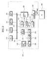
- FIG. 3 A block diagram of a multi-function machine having an image printing apparatus according to a preferred embodiment of the present invention is shown in Figure 3 .
- a multi-function machine 200 has an operating panel (OPE) 210, a Personal Computer (PC) interface 220, a storage unit 230, a scanning unit 240, a printing unit 250, a sensor unit 260, a facsimile unit 270 and a control unit 280.
- OPE operating panel
- PC Personal Computer
- the OPE 210 is provided with an input part (not shown) having plural function keys to support character and/or numerical inputs in order to activate various functions, supported by the multi-function machine 200, and function keys for setting sheet size.
- the OPE 210 also comprises an LCD window (not shown) to indicate the operational status of the multi-function machine 200 according to the control of the control unit 280, which is described below.
- the OPE 210 outputs key data generated on the basis of the operation of the keys provided in the input part to the control unit 280.
- the PC interface 220 supports data communication between an external personal computer (PC) 300 and the control unit 280 through a communication interface (P1284 or USB cable).
- the PC interface 220 receives printing data from the PC 300 and uploads to the PC 300 data read out by the scanning unit 240, which is described below, and the electric power supply state of the multi-function machine 200.
- the storage unit 230 is constructed using non-volatile memory such as a ROM to store various control programs necessary to implement the functions of the multi-function machine 200, and volatile memory such as a DRAM to store temporarily image data read out by the scanning unit 240 under the control of the control unit 280, facsimile data received from the facsimile unit 270 and printing data transmitted from the PC 300.
- non-volatile memory such as a ROM to store various control programs necessary to implement the functions of the multi-function machine 200
- volatile memory such as a DRAM to store temporarily image data read out by the scanning unit 240 under the control of the control unit 280, facsimile data received from the facsimile unit 270 and printing data transmitted from the PC 300.
- the storage unit 230 stores information indicating the positions at which white lines would be produced on printing sheets of different sizes, in the absence of the white line eliminating function of the multi-function machine.
- the positions at which the white line would have been produced depend upon sheet size but are invariant for each sheet size.
- the scanning unit 240 scans sheets of paper to produce images of the scanned sheets in a format that the control unit 280 can handle.
- the scanned data from the scanning unit 240 is temporarily stored in the storage unit 230.
- the scanned data stored in the storage unit 230 is transmitted to the printing unit 250 for printing under the control of the control unit 280 or transmitted to the PC 300 through the PC interface 220.
- the sensor unit 260 detects the operational status of individual units during the operation of the multi-function machine 200. That is, the sensor unit 260 checks whether the scanning unit 240, the printing unit 250, the PC interface 220, the facsimile unit 270, etc. are operating normally. The results of this checking are transmitted to the control unit 280 and the control unit 280 indicates the statuses of the units on the LCD window provided on the OPE 210. Therefore, a user can see the operational statuses of the various units using the LCD window.
- the facsimile unit 270 includes a telephone answering machine (TAM) 272 having an automatic answering function, a modem 274 and a line interface unit (LIU) 276.
- TAM telephone answering machine
- LIU line interface unit
- the modem 274 receives and transmits facsimile data from and to external devices connected to the public switched telephone network (PSTN) through the LIU 276.
- PSTN public switched telephone network
- the LIU 276 connects to enable bi-directional communication between the modem 274 and the PSTN to allow facsimile data to be received and transmitted. Facsimile data received through the PSTN is transmitted to the control unit 140 through the modem 274 and the LIU 276.
- the printing unit 250 carries out printing jobs under the control of the control unit 280.
- the printing unit 250 has a motor driver 252 and a print head driver 256.
- the motor driver 252 drives a carriage return (CR) motor 253 and a line feed (LF) motor 254 under the control of the control unit 280.
- the CR motor 254 is driven by the motor driver 252 to move the ink cartridge 150 transversely.
- the LF motor 253 is driven by the motor driver 252 to transport the sheet of paper for the recording of print data.
- the print head driver 256 drives the print head 258 to eject ink droplets from the nozzles, provided in the print head 258, to thereby print an image on a sheet of paper.
- the print head 258 has a plurality of nozzles, having discharge holes formed therein arranged and driven by the print head driver 256.
- control unit 280 controls its overall operation according to a control program stored in the storage unit.
- the control unit 280 checks whether information regarding the size of a sheet to be printed on has been input using the input part. If the sheet size information has been input, the control unit 280 uses the sheet size information to obtain the notional white line position from the storage unit 230.
- a document position sensor 262 is disposed on the sheet feeding path 100 near the paper feed exit of a the paper supply cassette 110.
- the document position sensor 262 is a sensor for detecting when a sheet of paper P fed along the sheet feeding path has reached a reference position.
- control unit 280 When the control unit 280 receives a detection signal, generated by the document position sensor 262, the control unit 280 drives the LF motor 253 to feed the sheet of paper P to a printing position.
- the sheet of paper P is moved along the sheet feeding path 100 by the paper feeding parts 130 which are rotated by the LF motor 253.
- the ink cartridge 150 is driven by the CR motor 254 and ejects ink droplets onto the sheet of paper P while reciprocating the print head (not shown) to the left and right to carry out printing jobs.
- control unit 280 decides by means of the document position sensor 262 that a sheet of paper P has reached the reference position, the control unit 280 causes the sheet of paper P to be fed at an initial feeding rate from the time when the sheet of paper P is detected to have reached at the set reference position to the time when the white line would be produced.
- the control unit 280 operates such that the sheet of paper P is fed at a rate different from the initial feeding rate for a predetermined period of time starting from the time when the white line would be produced on the sheet of paper P.
- control unit 280 stops driving the LF motor 253 for a predetermined period of time starting from the time when the white line would be produced on the sheet of paper P.
- control unit 280 controls the LF motor 253 for a predetermined period of time starting from the time when the white line would be produced on the sheet of paper P to feed the sheet of paper P at a rate less than the initial feeding rate.
- control unit 280 After a predetermined period of time has elapsed from the time when the white line would have been produced on the sheet of paper P, the control unit 280 causes the sheet of paper P to be fed at the initial feeding rate.
- control unit 280 checks whether information regarding the size of paper sheet to be printed on has been input through the OPE 210 (S400).
- control unit 280 feeds a sheet of paper P from the cassette 110 along the sheet feeding path 100 in response to a printing command (S410).
- the document position sensor 262 detects whether the sheet of paper P has reached the reference position and outputs a detection signal when this occurs to the control unit 280.
- the control unit 280 decides whether a detection signal is received from the document position sensor 262 (S420).
- control unit 280 drives the paper feeding part 130 at the initial feeding rate, and carries out a printing job to print an image on the sheet of paper P being fed (S430).
- the control unit 280 predicts the time when the white line would be produced on the sheet of paper P using the sheet size information. Accordingly, the control unit 280 checks the printing progress state starting from the time the sheet of paper P reaches the reference position and determines when the sheet of paper P has been fed up to the position where the white line would have been produced (S440). That is, the control unit 280 decides when the rear end portion of the sheet of paper P is being fed out from between the feeding roller 130a and the friction roller 130b.
- control unit 280 controls the LF motor 253 for a predetermined period of time, starting from the time when the white line would be produced on the sheet of paper P, to stop the feeding the sheet of paper P (S450).
- the control unit 280 stops feeding the sheet of paper P only for a predetermined period of time, starting from the time when the white line would be produced on the sheet of paper P, and feeds the sheet of paper P at the initial set feeding rate after the predetermined period of time has elapsed to continue the printing job.
- the control unit 280 determines whether the printing job is complete (S460). Upon determining that the print job is complete, the sheet of paper P, which has gone through the printing process, is discharged through the paper discharge part 140.
- the white line produced at the time the sheet of paper P goes out of the feeding roller 130a and the friction roller 130b can be prevented by controlling the feeding rate of the sheet of paper P at the time the white line would be produced on the sheet of paper P.
- the image printing apparatus and the white line compensation method uses information on positions set by sheet sizes at which the white line would be produced to control the sheet feeding rate for a predetermined period of time starting from the time when the white line would be produced on the sheet of paper, to thereby prevent the white line phenomenon so that printing quality can be enhanced.
Landscapes
- Physics & Mathematics (AREA)
- General Physics & Mathematics (AREA)
- Ink Jet (AREA)
- Handling Of Sheets (AREA)
- Facsimiles In General (AREA)
- Sheets, Magazines, And Separation Thereof (AREA)
- Handling Of Cut Paper (AREA)
Claims (16)
- Appareil d'impression comportant :un poste d'impression (150) ;une paire de rouleaux d'avance de feuilles coopérants (130a, 130b) sur le côté d'alimentation du poste d'impression (150), dont l'un est entraîne pour propulser une feuille (P) vers l'intérieur du poste d'impression (150) ; etun moyen de commande (280) destiné à commander l'avance de feuilles à travers le poste d'impression (150) ;caractérisé en ce que le moyen de commande (280) est configuré pour réduire l'entraînement appliqué audit rouleau entraîné (130a) tandis que la queue d'une feuille (P) est libérée d'entre ladite paire de rouleaux (130a, 130b) afin d'empêcher la formation d'une bande non imprimée à travers ladite feuille (P).
- Appareil selon la revendication 1, dans lequel ladite réduction de l'entraînement comprend un arrêt de l'entraînement dudit rouleau entraîné (130a).
- Appareil selon la revendication 1 ou 2, dans lequel le poste d'impression (150) comprend un moyen d'impression à jet d'encre.
- Appareil selon la revendication 1, 2 ou 3, comprenant un capteur (260) de position de document destiné à détecter une feuille (P) qui est alors entraînée vers le poste d'impression (150), dans lequel le moyen de commande (280) réagit à un signal de sortie de détection de feuilles du capteur (260) de position de document en déterminant le moment d'effectuer ladite réduction d'entraînement.
- Appareil selon la revendication 4, comportant en outre :une unité de stockage (230) dans laquelle est stockée une information concernant la position de la feuille dans laquelle une bande non imprimée serait produite pour différentes dimensions de feuilles ;dans lequel le moyen de commande (280) est configuré pour régler une vitesse d'avance des rouleaux d'avance (130a, 130b) en utilisant l'information stockée dans l'unité de stockage (230), la feuille (P) étant avancée à une vitesse d'avance établie initialement à partir du moment où la feuille (P) est détectée comme ayant atteint la position de référence établie par les capteurs (260) de position de document jusqu'à ce que la bande non imprimée soit produite, et la feuille (P) est avancée à une vitesse d'avance différente de la vitesse d'avance établie initialement à partir du moment où la bande non imprimée serait produite sur la feuille (P).
- Appareil selon la revendication 5, dans lequel le moyen de commande (280) est configuré pour prédire le moment où la bande non imprimée serait produite sur la feuille en utilisant l'information de dimension de feuille.
- Appareil selon la revendication 5 ou 6, dans lequel le moyen de commande (280) est configuré pour arrêter l'entraînement des rouleaux d'avance (130a, 130b) pendant une période de temps prédéterminée à partir du moment où la bande non imprimée serait produite sur la feuille (P).
- Appareil selon la revendication 5 ou 6, dans lequel le moyen de commande (280) est configuré pour commander la vitesse d'avance des rouleaux d'avance (130a, 130b) de manière que la feuille (P) soit avancée à une vitesse d'avance inférieure à la vitesse d'avance initialement établie pendant une période de temps prédéterminée commençant au moment où la bande non imprimée serait produite sur la feuille (P).
- Appareil selon la revendication 7 ou 8, dans lequel le moyen de commande (280) est configuré pour continuer de faire avancer la feuille (P) à la vitesse d'avance initialement établie après que la période de temps prédéterminée s'est écoulée.
- Appareil selon l'une quelconque des revendications précédentes, comportant en outre une unité de télécopie, comprenant :un modem (274) configuré pour recevoir et émettre des données de télécopie depuis et vers des dispositifs extérieurs connectés à un réseau téléphonique public commuté ; etune unité (276) d'interface de ligne configurée pour permettre des communications mutuelles entre le modem (274) et le réseau téléphonique public commuté.
- Appareil selon la revendication 10, dans lequel les données de télécopie reçues par l'intermédiaire du réseau téléphonique public commuté sont transmises au moyen de commande (280) en passant par le modem (274) et l'unité d'interface de ligne (276).
- Machine à fonctions multiples comprenant un appareil d'impression selon l'une quelconque des revendications précédentes, comportant en outre :un panneau d'exploitation (210) configuré pour supporter des entrées de caractères et/ou de nombres pour autoriser diverses fonctions supportées par la machine à fonctions multiples ;une unité d'interface (220) configurée pour recevoir des données d'impression transmises depuis un dispositif extérieur ;une unité de balayage (240) configurée pour balayer des données imprimées sur la feuille (P) ;dans laquelle le moyen de commande (280) est configuré pour vérifier si une information concernant la dimension de la feuille en file d'attente pour l'impression est appliquée en entrée par l'intermédiaire du panneau d'exploitation (210) et, à la suite de la détermination du fait qu'une information concernant la dimension de la feuille est appliquée en entrée, pour utiliser l'information de dimension afin de prédire une position de la feuille dans laquelle la bande non imprimée serait produite ; etune unité à capteur destinée à détecter des états de fonctionnement de dispositifs périphériques individuels en relation avec les opérations effectuées par la machine à fonctions multiples.
- Procédé d'impression comprenant :le fait de détecter si une feuille de papier (P) avancée le long d'un chemin d'avance de feuille atteint une position de référence établie ;l'entraînement de la feuille (P) le long du chemin d'avance de feuille à la suite de la détermination du fait que la feuille a atteint la position de référence établie conformément à une vitesse d'avance établie initialement ; etla réduction de la vitesse d'avance établie initialement pendant une période de temps prédéterminée à partir du moment où la queue de la feuille est libérée par une paire de rouleaux (130a, 130b) d'avance de feuille sur un côté d'alimentation d'un poste d'impression (150) afin d'empêcher la formation d'une bande non imprimée sur la feuille ; etla projection d'encre sur la feuille par l'intermédiaire d'une cartouche à encre lorsque la feuille atteint une zone d'impression.
- Procédé d'impression selon la revendication 13, comprenant en outre l'arrêt de l'avance de la feuille de papier pendant la période de temps prédéterminée à partir du moment où la bande non imprimée serait produite sur la feuille de papier.
- Procédé d'impression selon la revendication 13 ou 14, dans lequel, après l'écoulement de la période de temps prédéterminée, la feuille de papier est avancée conformément à la vitesse d'avance établie initialement.
- Procédé d'impression selon l'une quelconque des revendications 13 à 15, comprenant en outre :le stockage d'une information par l'intermédiaire d'une unité de stockage concernant des dimensions de feuille de la feuille de papier et une information en relation avec la position de la feuille de papier dans laquelle une bande non imprimée serait produite ; età la suite de la détection du fait que la feuille a atteint la position de référence établie, la commande de la vitesse d'avance de la feuille en utilisant l'information en relation avec une position de la feuille dans laquelle la bande non imprimée serait produite selon l'information de dimension de la feuille.
Applications Claiming Priority (2)
| Application Number | Priority Date | Filing Date | Title |
|---|---|---|---|
| KR2002059353 | 2002-09-30 | ||
| KR10-2002-0059353A KR100476771B1 (ko) | 2002-09-30 | 2002-09-30 | 화상인쇄장치 및 그의 화이트라인 보정방법 |
Publications (3)
| Publication Number | Publication Date |
|---|---|
| EP1403082A2 EP1403082A2 (fr) | 2004-03-31 |
| EP1403082A3 EP1403082A3 (fr) | 2004-06-30 |
| EP1403082B1 true EP1403082B1 (fr) | 2009-04-29 |
Family
ID=31973693
Family Applications (1)
| Application Number | Title | Priority Date | Filing Date |
|---|---|---|---|
| EP03256143A Expired - Lifetime EP1403082B1 (fr) | 2002-09-30 | 2003-09-29 | Dispositif ayant une fonction d'impression |
Country Status (5)
| Country | Link |
|---|---|
| US (1) | US7522305B2 (fr) |
| EP (1) | EP1403082B1 (fr) |
| KR (1) | KR100476771B1 (fr) |
| CN (1) | CN1256242C (fr) |
| DE (1) | DE60327402D1 (fr) |
Families Citing this family (8)
| Publication number | Priority date | Publication date | Assignee | Title |
|---|---|---|---|---|
| KR100490423B1 (ko) * | 2003-01-18 | 2005-05-17 | 삼성전자주식회사 | 토너를 이용하는 고속 이미지 형성 방법 및 장치 |
| JP4829717B2 (ja) * | 2006-08-23 | 2011-12-07 | キヤノン株式会社 | 記録装置及び搬送制御方法 |
| JP4379451B2 (ja) * | 2006-08-29 | 2009-12-09 | セイコーエプソン株式会社 | 印刷装置および連続印刷のための印刷媒体の搬送制御方法 |
| JP6123477B2 (ja) * | 2013-03-14 | 2017-05-10 | 株式会社リコー | 搬送装置、搬送装置の制御方法及び制御プログラム |
| KR102012890B1 (ko) * | 2013-03-25 | 2019-08-21 | 휴렛-팩커드 디벨롭먼트 컴퍼니, 엘.피. | 스캔 대상물의 위치에 따른 기능 수행 방법 및 이를 수행하기 위한 화상형성장치 |
| CN106956521A (zh) * | 2017-04-13 | 2017-07-18 | 深圳怡化电脑股份有限公司 | 一种打印机用走纸定位装置、打印机及银行自助终端 |
| CN114312059B (zh) * | 2021-12-28 | 2023-06-20 | 宁波得力科贝技术有限公司 | 给纸控制方法及打印机 |
| CN117734339A (zh) * | 2022-09-14 | 2024-03-22 | 浙江菜鸟供应链管理有限公司 | 打印纸、打印机、检测打印纸的系统、方法及装置 |
Family Cites Families (10)
| Publication number | Priority date | Publication date | Assignee | Title |
|---|---|---|---|---|
| US5372439A (en) * | 1992-12-18 | 1994-12-13 | Zebra Technologies Corporation | Thermal transfer printer with controlled ribbon feed |
| US6151478A (en) * | 1996-09-09 | 2000-11-21 | Minolta Co., Ltd. | Document feeder for a copying machine |
| JPH10101246A (ja) | 1996-09-30 | 1998-04-21 | Brother Ind Ltd | 用紙搬送装置および画像記録機 |
| JP3767061B2 (ja) | 1997-02-05 | 2006-04-19 | ブラザー工業株式会社 | 印字装置 |
| JP3630028B2 (ja) * | 1999-08-26 | 2005-03-16 | ブラザー工業株式会社 | 画像読取装置および記憶媒体 |
| US6314252B1 (en) * | 2000-03-09 | 2001-11-06 | Toshiba Tec Kabushiki Kaisha | Image forming apparatus and method of a forming image |
| US6824239B1 (en) * | 2000-09-13 | 2004-11-30 | Canon Kabushiki Kaisha | Printer with fast line-feed speed |
| JP4464003B2 (ja) | 2001-02-28 | 2010-05-19 | キヤノン株式会社 | 記録装置及び記録方法 |
| US6843547B2 (en) * | 2001-07-18 | 2005-01-18 | Lexmark International, Inc. | Missing nozzle detection method and sensor for an ink jet printer |
| US6540419B2 (en) * | 2001-08-21 | 2003-04-01 | Gerber Technology, Inc. | Multi-mode continuous printing |
-
2002
- 2002-09-30 KR KR10-2002-0059353A patent/KR100476771B1/ko not_active Expired - Fee Related
-
2003
- 2003-09-26 US US10/670,334 patent/US7522305B2/en not_active Expired - Fee Related
- 2003-09-29 DE DE60327402T patent/DE60327402D1/de not_active Expired - Lifetime
- 2003-09-29 EP EP03256143A patent/EP1403082B1/fr not_active Expired - Lifetime
- 2003-09-30 CN CNB031649289A patent/CN1256242C/zh not_active Expired - Fee Related
Also Published As
| Publication number | Publication date |
|---|---|
| DE60327402D1 (de) | 2009-06-10 |
| EP1403082A2 (fr) | 2004-03-31 |
| KR20040028217A (ko) | 2004-04-03 |
| US7522305B2 (en) | 2009-04-21 |
| CN1256242C (zh) | 2006-05-17 |
| US20040061875A1 (en) | 2004-04-01 |
| CN1496849A (zh) | 2004-05-19 |
| KR100476771B1 (ko) | 2005-03-16 |
| EP1403082A3 (fr) | 2004-06-30 |
Similar Documents
| Publication | Publication Date | Title |
|---|---|---|
| US8967890B2 (en) | Continuous sheet recording apparatus and method of controlling sorter in response to conveyance failure | |
| EP1403082B1 (fr) | Dispositif ayant une fonction d'impression | |
| JP4847249B2 (ja) | 画像記録装置、その装置によるインク予備吐出方法及びプログラム | |
| JP2010287092A (ja) | 画像形成システム | |
| JP2004017373A (ja) | 印刷装置 | |
| JP2023170172A (ja) | 記録装置、その制御方法およびプログラム | |
| JP2884523B2 (ja) | プリンタの媒体排出方法 | |
| JP4703389B2 (ja) | 画像形成装置 | |
| JP2001001617A (ja) | 画像記録装置 | |
| JP2003053953A (ja) | 印刷装置および縁無し印刷方法 | |
| JP2008238419A (ja) | マルチファンクション印刷装置、その制御方法、及びその制御プログラム | |
| JP2007106041A (ja) | インクジェット記録装置 | |
| JP2003025653A (ja) | 画像記録装置 | |
| KR100234428B1 (ko) | 용지걸림 자동검출 및 제거방법 | |
| JP2006123238A (ja) | 記録装置 | |
| JP4432296B2 (ja) | 印刷装置 | |
| JP2006168094A (ja) | 記録装置 | |
| JP7337488B2 (ja) | 記録装置、記録装置の制御方法、およびプログラム | |
| JP4616518B2 (ja) | 記録装置 | |
| JP2025083610A (ja) | 画像形成装置 | |
| JP2023073826A (ja) | 記録装置、制御方法、記憶媒体及びプログラム | |
| JP2000191158A (ja) | 印刷装置、印刷方法、印刷システム、及び記憶媒体 | |
| JP2025136675A (ja) | インクジェット記録装置およびノズルチェックパターン出力方法 | |
| JP2023051086A (ja) | 記録装置及び回復方法 | |
| JP3066033U (ja) | プリンタシステム |
Legal Events
| Date | Code | Title | Description |
|---|---|---|---|
| PUAI | Public reference made under article 153(3) epc to a published international application that has entered the european phase |
Free format text: ORIGINAL CODE: 0009012 |
|
| AK | Designated contracting states |
Kind code of ref document: A2 Designated state(s): AT BE BG CH CY CZ DE DK EE ES FI FR GB GR HU IE IT LI LU MC NL PT RO SE SI SK TR |
|
| AX | Request for extension of the european patent |
Extension state: AL LT LV MK |
|
| PUAL | Search report despatched |
Free format text: ORIGINAL CODE: 0009013 |
|
| AK | Designated contracting states |
Kind code of ref document: A3 Designated state(s): AT BE BG CH CY CZ DE DK EE ES FI FR GB GR HU IE IT LI LU MC NL PT RO SE SI SK TR |
|
| AX | Request for extension of the european patent |
Extension state: AL LT LV MK |
|
| RAP1 | Party data changed (applicant data changed or rights of an application transferred) |
Owner name: SAMSUNG ELECTRONICS CO., LTD. |
|
| 17P | Request for examination filed |
Effective date: 20040909 |
|
| AKX | Designation fees paid |
Designated state(s): DE FR GB NL |
|
| 17Q | First examination report despatched |
Effective date: 20070508 |
|
| GRAP | Despatch of communication of intention to grant a patent |
Free format text: ORIGINAL CODE: EPIDOSNIGR1 |
|
| GRAS | Grant fee paid |
Free format text: ORIGINAL CODE: EPIDOSNIGR3 |
|
| GRAA | (expected) grant |
Free format text: ORIGINAL CODE: 0009210 |
|
| AK | Designated contracting states |
Kind code of ref document: B1 Designated state(s): DE FR GB NL |
|
| REG | Reference to a national code |
Ref country code: GB Ref legal event code: FG4D |
|
| REF | Corresponds to: |
Ref document number: 60327402 Country of ref document: DE Date of ref document: 20090610 Kind code of ref document: P |
|
| PLBE | No opposition filed within time limit |
Free format text: ORIGINAL CODE: 0009261 |
|
| STAA | Information on the status of an ep patent application or granted ep patent |
Free format text: STATUS: NO OPPOSITION FILED WITHIN TIME LIMIT |
|
| 26N | No opposition filed |
Effective date: 20100201 |
|
| REG | Reference to a national code |
Ref country code: FR Ref legal event code: ST Effective date: 20100531 |
|
| PG25 | Lapsed in a contracting state [announced via postgrant information from national office to epo] |
Ref country code: FR Free format text: LAPSE BECAUSE OF NON-PAYMENT OF DUE FEES Effective date: 20090930 |
|
| PGFP | Annual fee paid to national office [announced via postgrant information from national office to epo] |
Ref country code: DE Payment date: 20130828 Year of fee payment: 11 Ref country code: NL Payment date: 20130827 Year of fee payment: 11 |
|
| PGFP | Annual fee paid to national office [announced via postgrant information from national office to epo] |
Ref country code: GB Payment date: 20130905 Year of fee payment: 11 |
|
| REG | Reference to a national code |
Ref country code: DE Ref legal event code: R119 Ref document number: 60327402 Country of ref document: DE |
|
| GBPC | Gb: european patent ceased through non-payment of renewal fee |
Effective date: 20140929 |
|
| PG25 | Lapsed in a contracting state [announced via postgrant information from national office to epo] |
Ref country code: NL Free format text: LAPSE BECAUSE OF NON-PAYMENT OF DUE FEES Effective date: 20150401 |
|
| PG25 | Lapsed in a contracting state [announced via postgrant information from national office to epo] |
Ref country code: DE Free format text: LAPSE BECAUSE OF NON-PAYMENT OF DUE FEES Effective date: 20150401 Ref country code: GB Free format text: LAPSE BECAUSE OF NON-PAYMENT OF DUE FEES Effective date: 20140929 |
|
| REG | Reference to a national code |
Ref country code: GB Ref legal event code: 732E Free format text: REGISTERED BETWEEN 20170406 AND 20170412 |